Note: Descriptions are shown in the official language in which they were submitted.
CA 02553499 2006-07-26
SURGICAL INSTRUMENT WITH AN ARTICULATING SHAFT
LOCKING MECHANISM
Field of the Invention
i000li The present invention relates in general to surgical instruments
that are suitable
for endoscopically inserting an end effector (e.g., endocutter, grasper,
cutter, staplers, clip
applier, access device, drug/gene therapy delivery device, and an energy
device using
ultrasound, RF, laser, etc.) to a surgical site, and more particularly to such
surgical
instruments with an articulating shaft.
Background of the Invention
100021 Endoscopic surgical instruments are often preferred over traditional
open surgical
devices since a smaller incision tends to reduce the post-operative recovery
time and
complications. Consequently, significant development has gone into a range of
endoscopic surgical instruments that are suitable for precise placement of a
distal end
effector at a desired surgical site through a cannula of a trocar. These
distal end effectors
engage the tissue in a number of ways to achieve a diagnostic or therapeutic
effect (e.g.,
endocutter, grasper, cutter, staplers, clip applier, access device, drug/gene
therapy
delivery device, and energy device using ultrasound, RF, laser, etc.).
100031 Positioning the end effector is constrained by the trocar.
Generally, these
endoscopic surgical instruments include a long shaft between the end effector
and a
handle portion manipulated by the clinician. This long shaft enables insertion
to a desired
depth and rotation about the longitudinal axis of the shaft, thereby
positioning the end
effector to a degree. With judicious placement of the trocar and use of
graspers, for
instance, through another trocar, often this amount of positioning is
sufficient. Surgical
stapling and severing instruments, such as described in U.S. Pat. No.
5,465,895, are an
example of an endoscopic surgical instrument that successfully positions an
end effector
by insertion and rotation.
100041 Depending upon the nature of the operation, it may be desirable to
further adjust
the positioning of the end effector of an endoscopic surgical instrument. In
particular, it is
often desirable to orient the end effector at an axis transverse to the
longitudinal axis of
the shaft of the instrument. The transverse movement of the end effector
relative to the
1.
CA 02553499 2006-07-26
instrument shaft is conventionally referred to as "articulation". This is
typically
accomplished by a pivot (or articulation) joint being placed in the extended
shaft just
proximal to the staple applying assembly. This allows the surgeon to
articulate the staple
applying assembly remotely to either side for better surgical placement of the
staple lines
and easier tissue manipulation and orientation. This articulated positioning
permits the
clinician to more easily engage tissue in some instances, such as behind an
organ. In
addition, articulated positioning advantageously allows an endoscope to be
positioned
behind the end effector without being blocked by the instrument shaft.
[0005] Approaches to articulating a surgical stapling and severing
instrument tend to be
complicated by integrating control of the articulation along with the control
of closing the
end effector to clamp tissue and fire the end effector (i.e., stapling and
severing) within
the small diameter constraints of an endoscopic instrument. Generally, the
three control
motions are all transferred through the shaft as longitudinal translations.
For instance,
U.S. Pat. No. 5,673,840 discloses an accordion-like articulation mechanism
("flex-neck")
that is articulated by selectively drawing back one of two connecting rods
through the
implement shaft, each rod offset respectively on opposite sides of the shaft
centerline.
The connecting rods ratchet through a series of discrete positions.
[0006] Another example of longitudinal control of an articulation mechanism
is U.S. Pat.
No. 5,865,361 that includes an articulation link offset from a camming pivot
such that
pushing or pulling longitudinal translation of the articulation link effects
articulation to a
respective side. Similarly, U.S. Pat. No. 5,797,537 discloses a similar rod
passing through
the shaft to effect articulation.
[0007] In U.S. Pat. No. 5,673,841, certain deficiencies were recognized for
then known
articulating surgical instruments for endosurgical stapling, cutting, clip
applying, and
grasping. Specifically, when the surgical articulating instruments are loaded,
the
articulating head on the instrument tends to move. This movement is usually a
combination of piece part deflection and slop (or backlash) in the
articulation mechanism.
High loads on the distal tip of the instrument (e.g., tissue clamping and
staple firing) are
reflected through the articulation device into the articulation control near
the handle and
can move (or rotate) the articulation control mechanism. In the past,
articulation joints
were designed with the articulation device performing double duty as the means
for both
2.
CA 02553499 2006-07-26
positioning and locking the articulated head of the instrument. An examination
of the
force application points for the load (tip of the instrument) and the
articulation device
(near the articulation joint) reveals a mechanical disadvantage for the
articulating device.
This disadvantage manifests itself as a magnification of tolerances or
clearances in the
articulating device, resulting in significant head movements.
[0008] In response to this recognized deficiency, several locking
mechanisms were
proposed. In particular, a locking mechanism locks a head at an angle of
articulation at all
times except when it is desired to articulate the head with respect to the
shaft. Upon
actuation of the articulation device, for example by pulling an articulation
band toward
the proximal end of the instrument, the locking mechanism releases, unlocking
the head
and allowing articulation thereof. Discontinuation of the articulation step,
for example, by
stoppage of pulling forces on the articulation band, causes the locking
mechanism to
reengage, locking the head of the instrument in its new angle of articulation.
In another
version, a pair of fluid bladders on each side allow fluid flow to shift side
to side to allow
pivoting of the head with a pinch blade blocking the fluid flow to "lock" the
articulating
pivot.
[0009] While the articulation band effectively achieved articulation and
simultaneous
unlocking of the articulation joint, it is believed that in certain
applications a direct
linkage between control and the articulation joint may be desirable. Achieving
proper
dimensioning of bands without slippage or breakage may be deemed difficult. A
degree
of slop in tactile response given by the articulation control may also be
undesirable.
100101 Consequently, a significant need exists for an articulating joint of
a surgical
instrument that is directly linked to an articulation control that
advantageously
incorporates automatic locking of the articulation joint for resisting
backdriving of the
end effector.
Brief Summary of the Invention
100111 The invention overcomes the above-noted and other deficiencies of
the prior art
by providing a surgical instrument whose elongate shaft pivotally articulates
in response
to an articulation linkage mechanism. Inadvertent change in this articulation
angle and/or
damage to the articulation linkage mechanism is avoided by an articulation
joint lock that
3.
CA 02553499 2006-07-26
resists backloading of the end effector. Thereby, the articulation linkage
mechanism may
have a desirably small cross section.
100121 In one aspect of the invention, a surgical instrument has an
articulation control
that a user actuates to cause pivoting of an end effector about an
articulation joint of an
elongate shaft. In particular, an articulation member extends a distal end
from the
elongate shaft into engagement with the end effector, being laterally
deflected in response
to the articulation control to effect articulation. In cooperation with this
movement, a
locking actuator is drawn proximally from the articulation joint, disengaging
from an
arcing braking surface attached to the end effector and radiating proximally
about an
articulation axis of the articulation joint. Thereby, a direct control of the
articulation
control is assisted by an articulation lock that maintains the end effector at
a selected
articulation angle without having to increase the size and strength of the
articulation
control to resist such backloading.
100131 In another aspect of the invention, a surgical instrument
incorporates an
articulation joint that is controlled by lateral movement of a slide bar in an
elongate shaft.
A proximally directed gear segment attached to the end effector and aligned
about an
articulation axis of the articulation joint engages a distally directed rack
on the slide bar.
A locking member in the elongate shaft also translates longitudinally and
distally into
engagement with the gear segment to lock the articulation joint in position.
Various
advantages afforded by differentially moving a slide bar to effect
articulation, such as
various forms of motive power, are thus realized with the assurance of
maintaining a
desired articulation angle by means of the articulation lock.
100141 In yet another aspect of the invention, a surgical instrument has an
articulating
shaft that is controlled by a slide bar received for lateral movement in the
elongate shaft.
A locking mechanism attached to the slide bar is advantageously moved into
engagement
with the elongate shaft in response to a backdriving force on the end
effector.
100151 These and other objects and advantages of the present invention
shall be made
apparent from the accompanying drawings and the description thereof
4.
CA 02553499 2006-07-26
Brief Description of the Figures
[0016] The accompanying drawings, which are incorporated in and constitute
a part of
this specification, illustrate embodiments of the invention, and, together
with the general
description of the invention given above and the detailed description of the
embodiments
given below, serve to explain the principles of the present invention.
[0017] FIGURE 1 is a front top perspective view of a surgical stapling and
severing
instrument shown with an open end effector, or staple applying assembly, and
with the
staple cartridge removed.
[0018] FIGURE 2 is a front top perspective view of the surgical stapling
and severing
instrument of FIG. 1 with an articulation mechanism actuated by a fluidic
actuation
control.
[0019] FIGURE 3 is a perspective disassembled view of an elongate shaft and
articulation mechanism of the surgical stapling and severing instrument of
FIG. 1.
[0020] FIGURE 4 is a perspective disassembled view of distal portions of an
implement
portion of the surgical stapling and severing instrument of FIG. 1, including
the staple
applying assembly and articulation mechanism.
[0021] FIGURE 5 is a top perspective view of the staple applying assembly
of FIGS. 1
and 4 with a lateral half of a staple cartridge removed to expose components
driven by a
firing motion.
100221 FIGURE 6 is a front perspective view of an implement portion of the
surgical
instrument of FIG. 1 with a double pivot closure sleeve assembly and end
effector
removed to expose a single pivot frame ground articulated by a fluidic
articulation
mechanism.
[0023] FIGURE 7 is perspective detail view of an alternative articulation
joint for the
surgical instrument of FIG. 1 depicting a double pivoting closure sleeve
assembly at a
proximal position with a single pivot frame ground.
[0024] FIGURE 8 is a bottom right perspective exploded view of the
alternative
articulation joint of FIG. 7 including a double pivoting fixed-wall dog bone
link and a
frame ground incorporating rail guides for a lateral moving member (T-bar).
5.
CA 02553499 2006-07-26
[0025] FIGURE 9 is top left perspective exploded view of a further
alternative
articulation joint for the surgical instrument of FIG. 1, including an
alternate solid wall
support plate mechanism incorporated into a lower double pivot link to support
a firing
bar and includes a rail guided laterally moving member (T-bar).
[0026] FIGURE 10 is a top diagrammatic view of an alternate articulation
locking
mechanism for the surgical instrument of FIG. 1 with a closure sleeve assembly
removed
to expose a backloading disengaged T-bar for automatic articulation lock
engagement and
disengagement.
[0027] FIGURE 11 is a top diagrammatic view of an additional alternative
articulation
mechanism for the surgical instrument of FIG. 1, a spring biased rack on a T-
bar with
locking features that engage due to backloading from an end effector.
[0028] FIGURE 12 is an alternative T-bar and frame ground incorporating
lateral
guidance for the surgical instrument of FIG. 1.
[0029] FIGURE 13 is yet an additional alternative T-bar and frame ground
incorporating
lateral guidance for the surgical instrument of FIG. 1.
[0030] FIGURE 14 is a left top perspective disassembled view of an
alternative
articulation mechanism including a double pivoting frame assembly and single
pivoting
closure sleeve assembly for the surgical instrument of FIG. 1.
100311 FIGURE 15 is a left bottom perspective view of the alternative
articulation
mechanism of FIG. 14.
[0032] FIGURE 16 is a diagram of a laterally moving fluidic articulation
mechanism with
rack and gear segment pivoting depicted in a nonarticulated state.
[0033] FIGURE 17 is cross section front view in elevation of the fluidic
articulation
mechanism of FIG. 16 taken along lines 17-17.
[0034] FIGURE 18 is a diagram of the laterally moving fluidic articulation
mechanism
with a rack and gear segment pivoting depicted in an articulated state.
[0035] FIGURE 19 is cross section front view in elevation of the fluidic
articulation
mechanism of FIG. 18 taken along lines 19-19.
6.
CA 02553499 2006-07-26
[0036] FIGURE 20 is a top diagrammatic view of a surgical instrument
articulated by at
least one longitudinally moving member that laterally cams a slide bar, which
in turn
articulates an end effector.
[0037] FIGURE 21 is a top diagrammatic view of the surgical instrument of
FIG. 20 in an
articulated state.
[0038] FIGURE 22 is front cross section view in elevation of an alternative
rotary link
mechanical control system for a surgical instrument of FIGS. 16 or 20 for
laterally
translating respectively a T-bar or slide bar, depicted in an unarticulated
state.
[0039] FIGURE 23 is a front cross section view in elevation of the
alternative rotary link
mechanical control system of FIG. 22 in an articulated state.
[0040] FIG. 24 depicts a perspective, exploded view of an alternative
lateral articulation
control mechanism for the alternative rotary link mechanical control system of
FIG. 22.
[0041] FIG. 25 depicts a front elevation view in section of the lateral
articulation control
mechanism of FIG. 24.
[0042] FIG. 26 depicts a detail view of a locking block in an engaged state
of the lateral
articulation control mechanism of FIG. 24.
[0043] FIG. 27 depicts a detail view of the lateral articulation control
mechanism of FIG.
24 in a disengaged state.
Detailed Description of the Invention
Overview of articulating shaft.
[0044] Turning to the Drawings, wherein like numerals denote like
components
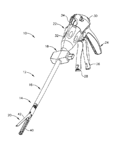
throughout the several views, FIG. 1 depicts a surgical instrument, which in
the
illustrative versions is more particularly a surgical stapling and severing
instrument 10,
that is capable of practicing the unique benefits of the present invention. In
particular, the
surgical stapling and severing instrument 10 is sized for insertion, in a
nonarticulated state
as depicted in FIG. 1, through a trocar cannula passageway to a surgical site
in a patient
(not shown) for performing a surgical procedure. Once an implement portion 12
is
inserted through a cannula passageway, an articulation mechanism 14
incorporated into a
7.
CA 02553499 2006-07-26
distal portion of an elongate shaft 16 of the implement portion 12 may be
remotely
articulated, as depicted in FIG. 2, by an articulation control 18. An end
effector, depicted
in the illustrative version as a staple applying assembly 20, is distally
attached to the
articulation mechanism 14. Thus, remotely articulating the articulation
mechanism 14
thereby articulates the staple applying assembly 20 from a longitudinal axis
of the
elongate shaft 16. Such an angled position may have advantages in approaching
tissue
from a desired angle for severing and stapling, approaching tissue otherwise
obstructed
by other organs and tissue, and/or allowing an endoscope to be positioned
behind and
aligned with the staple applying assembly 20 for confirming placement.
Handle.
100451 The surgical and stapling and severing instrument 10 includes a
handle portion 22
proximally connected to the implement portion 12 for providing positioning,
articulation,
closure and firing motions thereto. The handle portion 22 includes a pistol
grip 24 toward
which a closure trigger 26 is pivotally and proximally drawn by the clinician
to cause
clamping, or closing, of the staple applying assembly 20. A firing trigger 28
is farther
outboard of the closure trigger 26 and is pivotally drawn by the clinician to
cause the
stapling and severing of tissue clamped in the staple applying assembly 20.
Thereafter, a
closure release button 30 is depressed to release the clamped closure trigger
26, and thus
the severed and stapled ends of the clamped tissue. The handle portion 22 also
includes a
rotation knob 32 coupled for movement with the elongate shaft 16 to rotate the
shaft 16
and the articulated staple applying assembly 20 about the longitudinal axis of
the shaft 16.
The handle portion 22 also includes a firing retraction handle 34 to assist in
retracting a
firing mechanism (not depicted in FIGS. 1-2) should binding occur, so that
opening of the
staple applying assembly 20 may occur thereafter.
100461 It will be appreciated that the terms "proximal" and "distal" are
used herein with
reference to a clinician gripping a handle of an instrument. Thus, the
surgical stapling
assembly 20 is distal with respect to the more proximal handle portion 22. It
will be
further appreciated that for convenience and clarity, spatial terms such as
"vertical" and
"horizontal" are used herein with respect to the drawings. However, surgical
instruments
are used in many orientations and positions, and these terms are not intended
to be
limiting and absolute.
8.
CA 02553499 2013-12-09
[0047] An illustrative multi-stroke handle portion 22 for the surgical
stapling and
severing instrument 10 of FIGS. 1-2 is described in greater detail in the co-
pending and
commonly-owned U.S. patent application entitled "SURGICAL STAPLING
INSTRUMENT INCORPORATING A MULTISTROKE FIRING POSITION
INDICATOR AND RETRACTION MECHANISM" to Swayze and Shelton IV, Ser. No.
10/674,026 with additional features and variation as described herein. While a
multi-
stroke handle portion 22 advantageously supports applications with high firing
forces
over a long distance, applications consistent with the present invention may
incorporate a
single firing stroke, such as described in co-pending and commonly owned U.S.
patent
application "SURGICAL STAPLING INSTRUMENT HAVING SEPARATE
DISTINCT CLOSING AND FIRING SYSTEMS" to Frederick E. Shelton IV, Michael E.
Setser, and Brian J. Hemmelgam, Ser. No. 10/441,632.
Implement Portion (Articulating Elongate Shaft And Staple Applying Assembly).
100481 In FIGS. 1-5, the implement portion 12 advantageously incorporates
the multiple
actuation motions of longitudinal rotation, articulation, closure and firing
within a small
diameter suitable for endoscopic and laparoscopic procedures. The staple
applying
assembly 20 ("end effector") has a pair of pivotally opposed jaws, depicted as
an elongate
channel 40 with a pivotally attached anvil 42 (FIGS. 1-2, 4-5). Closure and
clamping of
the anvil 42 to the elongate channel 40 is achieved by longitudinally
supporting the
elongate channel 40 with a frame assembly 44 (FIG. 3) rotatingly attached to
the handle
portion 22 over which a double pivot closure sleeve assembly 46 longitudinally
moves to
impart a closing and opening respectively to a distal and proximal motion to
the anvil 42,
even with the staple applying assembly 20 articulated as in FIG. 2.
[0049] With particular reference to FIG. 3, the frame assembly 44 includes
a single pivot
frame ground 48 whose proximal end is engaged to the rotation knob 32, with a
right half
shell 50 thereof shown in FIG. 3. It should be appreciated that a proximal end
of the
closure sleeve assembly 46, specifically of a closure straight tube 52, with
one end
encompassing the proximal end of the frame ground 48 and the other end passing
into the
handle portion 22, engages closure components (not shown) that longitudinally
translate
9.
CA 02553499 2006-07-26
the closure sleeve assembly 46. A circular lip 54 at the proximal end of the
closure
straight tube 52 provides a rotating engagement to such components. Engaging
components of the rotation knob 32 pass through a longitudinal slot 56 on a
proximal
portion of the straight closure tube 52 to engage an aperture 58 which is
proximally
positioned on the frame ground 48. The longitudinal slot 56 is of sufficient
length to
allow the longitudinal closure translation of the closure sleeve assembly 46
even at
various rotational angles set by the rotation knob 32 of the closure sleeve
assembly 46
and the frame ground 48.
[0050] The elongate shaft 16 supports the firing motion by receiving a
firing rod 60 that
rotatingly engages firing components of the handle portion 22 (not shown). The
firing rod
60 enters a proximal opening 62 along the longitudinal centerline of the frame
ground 48.
The distal portion of the frame ground 48 includes a firing bar slot 64 along
its bottom
that communicates with the proximal opening 62. A firing bar 66 longitudinally
translates
in the firing bar slot 64 and includes an upwardly projecting proximal pin 68
that engages
a distal end 70 of the firing rod 60.
100511 The elongate shaft 16 supports articulation by incorporating a
rectangular
reservoir cavity 72, one lateral portion depicted in a distal portion of the
rotation knob 32.
A bottom compat __ tment 74 that resides within the rectangular reservoir
cavity 72 has
laterally spaced apart left and right baffles 76, 78. An articulation actuator
80 slides
laterally overtop of the bottom compaitment 74, its downward laterally spaced
left and
right flanges 82, 84, which are outboard of the baffles 76, 78, each
communicating
laterally to left and right push buttons 86, 88 that extend outwardly from the
respective
shell halves of the rotation knob 32. The lateral movement of the articulation
actuator 80
draws left and right flanges 82, 84 nearer and farther respectively to the
left and right
baffles 76, 78, operating against left and right reservoir bladders 90, 92 of
a fluidic
articulation system 94, each reservoir bladder 90, 92 communicating
respectively and
distally to left and right fluid conduits or passageways 96, 98 that in turn
communicate
respectively with left and right actuating bladders 100, 102. The latter
oppose and
laterally pivot a T-bar 104 of the articulation mechanism 14.
100521 The frame assembly 44 constrains these fluidic actuations by
including a top and
distal recessed table 106 of the frame ground 48 upon which resides the fluid
passages 96,
10.
CA 02553499 2006-07-26
98 and actuating bladders 100, 102. The T-bar 104 also slidingly resides upon
the
recessed table 106 between the actuating bladders 100, 102. Proximal to the T-
bar 104, a
raised barrier rib 108 is aligned thereto, serving to prevent inward expansion
of the fluid
passages 96, 98. The frame assembly 44 has a rounded top frame cover (spacer)
110 that
slides overtop of the frame ground 48, preventing vertical expansion of the
fluid passages
96, 98 and actuating bladders 100, 102, as well as constraining any vertical
movement of
the T-bar 104. In particular, the frame cover 110 includes features that
enable it to also
provide an articulation locking member 111, described in greater detail below
as part of
an articulation locking mechanism 113.
100531 A distal end ("rack") 112 of the T-bar 104 engages to pivot a
proximally directed
gear segment 115 of an articulated distal frame member 114 of the articulation
mechanism 14. An articulated closure tube 116 encompasses the articulated
distal frame
member 114 and includes a horseshoe aperture 118 that engages the anvil 42. A
double
pivoting attachment is formed between the closure straight tube 52 and
articulating
closure ring 116 over the articulating mechanism 14, allowing longitudinal
closure
motion even when the articulating mechanism 14 is articulated. In particular,
top and
bottom distally projecting pivot tabs 118, 120 on the closure straight tube 52
having pin
holes 122, 124 respectively are longitudinally spaced away from corresponding
top and
bottom proximally projecting pivot tabs 126, 128 on the articulating closure
ring 116
having pin holes 130, 132 respectively. An upper double pivot link 134 has
longitudinally
spaced upwardly directed distal and aft pins 136, 138 that engage pin holes
130, 122
respectively and a lower double pivot link 140 has longitudinally spaced
downwardly
projecting distal and aft pins 142, 144 that engage pin holes 132, 124
respectively. A
vertical pin hole 169 distally positioned through the frame ground 48 receives
a frame
pivot pin 171 that pivots in an underside of the distal frame member 114.
100541 With particular reference to FIG. 4, the articulating closure ring
116 is shown for
enhanced manufacturability to include a short tube 146 attached to an
articulating
attachment collar 148 that includes the proximally projecting pivot tabs 126,
128.
Similarly, the straight closure tube 52 is assembled from a long closure tube
150 that
attaches to an aft attachment collar 152 that includes the distally projecting
pivot tabs
119, 120. The horseshoe aperture 118 in the short closure tube 146 engages an
upwardly
11.
CA 02553499 2013-12-09
projecting anvil feature 154 slightly proximal to lateral pivot pins 156 that
engage pivot
recesses 158 inside of the elongate channel 40.
100551 The alternative version of FIG. 4 includes a dog bone link 160
instead of a frame
pivot pin 171 whose proximal pin 157 pivotally attaches to the frame ground 48
in a
frame hole 161 and whose distal pin 159 rigidly attaches to a proximal
undersurface 162
of the articulating distal frame member 114, thereby providing pivotal support
there
between. A bottom longitudinal knife slot 163 in the dog bone link 160 guides
an
articulating portion of the firing bar 66. The articulating distal frame
member 114 also
includes a bottom longitudinal slot 164 for guiding a distal portion of the
firing bar 66.
Staple Applying Apparatus (End Effector).
100561 With reference to FIGS 4-5, the firing bar 66 distally terminates in
an E-beam 165
that includes upper guide pins 166 that enter an anvil slot 168 in the anvil
42 to verify and
assist in maintaining the anvil 42 in a closed state during staple formation
and severing.
Spacing between the elongate channel 40 and anvil 42 is further maintained by
the E-
beam 165 by having middle pins 170 slide along the top surface of the elongate
channel
40 while a bottom foot 172 opposingly slides along the undersurface of the
elongate
channel 40, guided by a longitudinal opening 174 in the elongate channel 40. A
distally
presented cutting surface 176 of the E-beam 165, which is between the upper
guide pins
166 and middle pins 170, severs clamped tissue while the E-beam 165 actuates a
replaceable staple cartridge 178 by distally moving a wedge sled 180 that
causes staple
drivers 182 to cam upwardly driving staples 184 out of upwardly open staple
holes 186 in
a staple cartridge body 188, forming against a staple forming undersurface 190
of the
anvil 42. A staple cartridge tray 192 encompasses from the bottom the other
components
of the staple cartridge 178 to hold them in place. The staple cartridge tray
192 includes a
rearwardly open slot 194 that overlies the longitudinal opening 174 in the
elongate
channel 40, thus the middle pins 170 pass inside of the staple cartridge tray
192.
100571 The staple applying assembly 20 is described in greater detail in co-
pending and
commonly-owned U.S. Patent Application Ser. No. 10/955,042, "ARTICULATING
SURGICAL STAPLING INSTRUMENT INCORPORATING A TWO-PIECE E-BEAM
FIRING MECHANISM" to Frederick E. Shelton IV, et al., filed 30 September 2004.
12.
CA 02553499 2006-07-26
Articulation Locking Mechanism.
= 100581 In FIGS. 3-4, and 6-8, an articulation lock mechanism 200
is advantageously
incorporated to maintain the staple applying assembly 20 at a desired
articulation angle.
The articulation lock mechanism 200 reduces back driven loads on the left and
right
actuating bladders 100, 102. In particular, a compression spring 202 (FIG. 3)
is
proximally positioned between a proximal end 204 of the articulation locking
member
111 and the handle portion 22, biasing the articulation locking member 111
distally. With
particular reference to FIG. 4, two parallel slots 206, 208 at a distal end
210 of the
articulation locking member 111 receive respectively upwardly projecting guide
ribs 212,
214 on the frame ground 48. The guide ribs 212, 214 are longitudinally shorter
than the
parallel slots 206, 208 allowing a range of relative longitudinal travel.
Thereby, with
particular reference to FIG. 8, selective abutting engagement of a distal
frictional surface,
depicted as a toothed recess 216 distally projecting from the articulation
locking member
111 is engaged to a corresponding locking gear segment 217 in a brake plate
218 received
into a top proximal recess 220 (FIG. 4) of the articulating frame member 114.
Distal and
proximal holes 221, 222 in the brake plate 218 receive distal and proximal
pins 223, 224
that upwardly project from the top proximal recess 220.
100591 With particular reference to FIG. 6, the elongate shaft 16
is depicted in an
articulated position with the closure sleeve assembly 46 removed from around
the frame
assembly 44 and without the elongate channel 40 and anvil 42. Articulation
actuator 80 is
shown moved laterally to the left to compress right proximal reservoir bladder
92 and
expand distal right actuation bladder 102 moving T-bar 104 to the position
shown. Thus,
lateral movement of the articulation actuator 80 articulates the distal frame
114 clockwise
about the single pivot frame ground 48 as viewed from above. The articulation
actuator
80 advantageously also automatically engages and disengages the articulation
lock
mechanism 200. In particular, a toothed detent surface 225 along a proximal
top surface
of the articulation actuator 80 receives a downwardly projecting locking pin
226 from the
proximal end 204 of the articulation locking member 111 (not shown in FIG. 6).
The
engagement of the locking pin 226 within the root of the toothed detent
surface 225
provides sufficient distal movement of the articulation locking member 111 for
locking
engagement of the locking gear segment 217 in the brake plate 218. Lateral
movement by
an operator of the articulation member 80 proximally urges the locking pin 226
13.
CA 02553499 2006-07-26
, .
proximally, and thus disengages the articulation locking member 111 from the
brake plate
218. When the operator releases the articulation actuator 80, the locking pin
226 is urged
by the compression spring 202 into the adjacent detent in detent surface 225
to lock the
locking mechanism 111, and thereby the staple applying assembly 20,
constraining the
articulation mechanism 14 at a desired articulation position by constraining
and
expanding the inflated shape of the proximal left and right reservoir bladders
90, 92.
100601 Alternatively or additionally, an orifice may be provided
within parallel fluid
conduits 96, 98 to control the flow rate between the distal actuating bladders
100,102 and
proximal reservoir bladders 90, 92.
100611 In FIG. 10, an alternate locking mechanism 2000 of an
articulation mechanism
2002 of a surgical instrument 2004, is normally unlocked and is activated by
cocking a
laterally moving T-bar 2006 due to back loading. A slot 2008 is located in a
frame ground
2010 to receive and guide a rib 2012 extending down from the T-bar 2006. A
slender
longitudinal section 2014, which is orthogonally attached to the rib 2012
deflects if an
end effector 2016 is backloaded. For instance, as the end effector 2016 is
forced to the
right as depicted at arrow 2018, for instance, its proximal gear segment 2020
acts upon a
rack 2022 of the T-bar 2006, imparting a nonorthogonal backdriving force, as
depicted at
arrow 2024. Thus, the slender longitudinal section 2014 bends, cocking rib
2012 in slot
2008. This cocking produces opposing binding forces, as depicted by arrows
2026, 2028,
that lock the T-bar 2006 and prevent further articulation. Unlocking occurs
when
actuation of the articulation bladders uncocks the laterally moving T-bar
2006.
Thereafter, the rib 2012 may assist in guiding the T-bar 2006.
[0062] In FIG. 11, yet an additional articulation locking
mechanism 2100 for a surgical
instrument 2102 is depicted that is normally unlocked and activated by the
proximal force
vector from the twenty (20) degree pressure angle from gear teeth 2104 of an
end effector
2106 and rack teeth 2108 of a T-bar 2110. When the end effector 2106 is
backloaded, as
depicted by nonorthogonal arrow 2112, the longitudinal vector of the pressure
angle,
depicted as arrow 2114, moves the T-bar 2110 proximally. This longitudinal
force vector
is applied to a stiff spring 2118 behind a rack 2120 of the T-bar 2110. When
the spring
2118 deflects as T-bar 2110 moves proximally, locking teeth 2126 projecting
proximally
from the rack 2120 are brought into engagement with locking elements 2122
distally
14.
CA 02553499 2006-07-26
projecting and laterally aligned on a ground frame 2124. The locking teeth
2126 and
locking elements 2122 disengage when the proximal force vector 2014 is reduced
or
eliminated by removing the back loading of the end effector 2106 and allowing
T-bar
2110 to move distally from urging from spring 2118.
Double Pivot Closure Sleeve and Single Pivot Frame Ground Combination.
[0063] With reference to FIGS. 3-4 and 7, the implement portion 12
advantageously
incorporates the double pivot closure sleeve assembly 46 that longitudinally
translates
over and encompasses a single pivot frame ground 48. These mechanisms and
their
operation will now be described in further detail. With particular reference
to FIG. 7, the
articulation mechanism 14 is depicted in an articulated state with the closure
sleeve
assembly 46 retracted proximally to an anvil open state. With the anvil 42
open (not
shown in FIG. 7), actuation of the articulation control 18 causes the
articulated closure
ring 116 to pivot about the upwardly directed distal pin 136 and downwardly
directed
distal pin 142 (not shown in FIG. 7) respectively of the upper and lower
double pivot
closure links 134, 140. The frame ground 48 pivots around a single pin,
depicted as the
frame pivot pin 171 (FIG. 3) that joins frame ground 48 to distal frame member
114. With
the anvil 42 open, the frame pivot pin 171 of frame ground 48 is aligned with
the distal
most position of upper and lower double pivot links 134, 140 of the closure
sleeve
assembly 46. This positioning allows easy pivoting and rotation of the staple
applying
assembly 20 while the anvil 42 is open. When the closure sleeve assembly 46 is
moved
distally to pivot anvil 42 closed, the closure straight tube 52 moves distally
about frame
ground 48 and the articulated closure ring 116 moves distally along the
articulated distal
frame member 114 axis as urged by pivot links 134, 140. Dual pivoting pins
136, 138 and
142, 144 on links 134, 140 facilitate engagement with closure straight tube 52
and
articulated closure ring 116 as they are urged towards the distal closure
position when the
device is articulated (not shown). At the distal closure position, the frame
pivot pin 171 is
vertically aligned with proximal pivot pins 138, 144 at full articulation or
may fall at any
point between distal pins 136, 142 and proximal pins 138, 144 while working
effectively.
Solid Firing Bar Support.
[0064] In FIG. 8, the articulation mechanism 14 of FIG. 7 is partially
exploded and
viewed from the bottom, showing a solid wall firing bar support design (dog
bone link
15.
CA 02553499 2006-07-26
160) of FIG. 4 that offers advantages over conventional flexible support
plates. Support
plates are used to bridge the gap and guide and support the firing bar 66
through a single
frame ground pivot articulation joint 1801. Flexible firing bars are known,
but the
incorporation of solid wall firing bars such as those shown in FIGS. 4, 8 and
9 offer
unique advantages. Referring now to FIG. 8, frame ground 48 includes a frame
knife slot
1802 that runs along the bottom of frame ground 48 and a distal knife slot 164
runs along
the bottom of the articulating distal frame member 114 for the sliding
reception of the
firing bar 66 (not shown) therein. Frame ground 48 is described above and
includes a
direct single pivotal connection at frame pivot pin 171 with the distal frame
member 114.
The fixed wall dog bone link 160 that is rotatably connected on proximal pin
end 157 and
movably connected on distal pin end 159 includes left and right lateral guides
1818, 1820,
defining therebetween a guidance slot 1822 for sliding passage of a firing bar
66 (FIG. 4).
[0065] Thus, to bridge the gap between frame ground 48 and the distal frame
member
114, the fixed wall pivoting dog bone link 160 is pivotally attached to frame
ground 48
and is slidingly attached to frame member 114. Proximal pin 157 of the
pivoting dog bone
160 is pivotally received in a bore 1824 in frame ground 48 enabling pivotal
dog bone
160 to pivot about pocket 1824. A distal pin 159 extends upwards from pivotal
dog bone
160 and is slidingly received in a slot 1826 in distal frame member 114.
Articulation of
staple applying assembly 20 to an angle such as 45 degrees from the
longitudinal axis
pivots pivoting dog bone 116 in bore 1824 at its proximal pin 157 and distal
pin 159
slides into slot 1826 formed in the distal frame member 114 to bend firing bar
66 to two
spaced-apart angles that are half of the angle of the staple applying assembly
20. Unlike
previously referenced flexible support plates that bend the firing bar 66 to a
45 degree
angle, the fixed wall pivoting dog bone 160 bends the firing bar 66 to two
spaced-apart
angles such as 22.5 degrees each. Bending the flexible firing bar or bars 66
to half the
angle cuts the bend stress in the firing bars 66 to one-half of that found in
conventional
articulation supports. Reducing the bending stress in the firing bars 66
reduces the
possibility of permanently bending or placing a set in the firing bars,
reduces the
possibility of firing jams, ensures lower firing bar retraction forces, and
provides
smoother operation of the firing system.
100661 In FIG. 9, a surgical instrument 1900 includes double closure pivot.
Single frame
pivot articulation joint 1902 shows an alternate solid wall support plate
mechanism 1904
16.
CA 02553499 2006-07-26
that replaces the lower double pivot link 140 and dog bone link 1812 of FIG.
8. Left and
right firing bar supports 1906, 1908 extend upwardly from a lower double pivot
link 1910
of a closure sleeve assembly 1912. Clearance 1914 is provided in a frame
ground 1916
for the firing bar supports 1906, 1908 to travel as the closure sleeve
assembly 1912 moves
distally to close the anvil 42 (not shown in FIG. 9) and proximally to open
anvil 42. Like
the above described pivoting dog bone 160, the alternate lower double pivoting
link 1910
also bends and supports the firing bar 66 (not shown in FIG. 9) creating two
spaced apart
bend angles that are up to one-half of the bend angle of the staple applying
assembly 20.
Lateral Member Guide Mechanisms.
100671 With further reference to FIG. 9, left and right upward flanges
1918, 1920 on the
frame ground 1916 include distal and proximal lateral pin guides 1921, 1922,
1923, 1924
that pass laterally through holes 1923, 1924 in a T-bar 1926 assisting in
minimizing
binding in an articulation mechanism 1928. These pin guides 1921, 1922 are
also
incorporated into the frame ground 48 of FIG. 7. As another example, in FIG.
7, the T-bar
104 advantageously includes a dovetail lateral guide 1930 that laterally
slides within a
dovetail channel 1932 formed in the frame ground 48. As yet a further example,
in FIG.
12, a raised rib 1934 on a frame ground 1936 is received within a rectangular
slot 1938
formed in a T-bar 1940. To further facilitate non-binding lateral translation,
distal and
proximal lateral bearing tracks 1942, 1944 each include a respective plurality
of ball
bearings 1946, 1948. As yet a further example, in FIG. 13, a plurality of
frame lateral
grooves 1950-1954 are formed in a frame ground 1956 with corresponding T-bar
lateral
grooves 1958-1962 in a T-bar 1964. Slide rollers 1966-1970 reside trapped
within
respective pairs of lateral grooves 1950/1958, 1952/1960, 1954/1962. These are
by no
means an exhaustive list of lateral guidance members that prevent unwanted
cocking or
rotation of the T-bar 1964.
Double Pivot Frame Ground and Single Pivot Closure Combination.
100681 In FIGS. 14-15, an alternate frame ground and closure mechanism 2200
is
incorporated into a surgical instrument 2202 that includes double pivoting
frame
assembly 2204. In particular, a frame ground 2206 is connected to distal frame
member
2208 by a dual pivot frame dog bone 2210 having a proximal pivot pin 2212
pivotally
engaging a proximal bore 2214 in frame ground 2206 and a distal pivot pin 2216
17.
CA 02553499 2006-07-26
engaging a distal bore 2218 of distal frame member 2208. A guidance slot 2220
is located
on the underside of dog bone 2210 for the guidance of a firing bar 66 (not
shown in FIGS.
14-15) therein. Knife slot 2222 is located in distal frame member 2208. As
shown,
articulation of a closure ring 2230 of a closure sleeve assembly 2224 to a
forty-five (45)
degree angle articulates distal frame member 2208 to a forty-five (45) degree
angle and
articulates frame dog bone 2210 to half that angle. Consequently, firing bar
66 is
subjected to the two shallow half bends that are spaced apart and obtains all
the benefits
listed above.
100691 Outermost closure sleeve assembly 2224 is different in that only one
pivot axis of
the double pivoting design of the frame assembly 2204 accommodates its
longitudinal
closure motion. As shown, a closure tube shaft 2226 has a clevis 2228 at a
distal end.
Clevis 2228 is pivotally engaged with the closure ring 2230. Closure ring 2230
has a
proximal gear 2232 formed at a distal end. A pin 2234 passes through the
proximal gear
2232 and pivotally engages an upper tang 2236 of clevis 2228. A lower arm 2238
is
pivotally engaged to a lower tang 2240 of clevis 2228 by an aligned pin 2241.
Holes 2242
in the clevis 2228 receive lateral guides pins 2243 and slidably attach a T-
bar 2244
therein to engage proximal gear 2232 of the closure ring 2230. Thus, this
alternate
mechanism 2200 uses a reversed single/dual pivot alternate concept from the
previously
described mechanism. That is, the alternate closure mechanism 2200 has a
single pivot
and the alternate frame ground has a dual pivot, unlike the previously
described dual
pivot closure mechanism with a single pivot frame ground.
Laterally Moving Articulation Mechanism
[0070] In FIGS. 16-19, a laterally moving articulation mechanism 230 is
depicted
schematically to show lateral motion being used to effect articulation of an
end effector
232. Lateral motion is the movement of at least one element toward or away
from the
longitudinal axis of a surgical device 234. This motion is generally at right
angles to the
longitudinal axis, which is a horizontal line bisecting the mechanism 230, and
does not
involve rotational motion or longitudinal motion. Laterally moving
articulation
mechanisms can be fluid actuated as shown in FIGS. 16-19 or mechanically
actuated as
shown in FIGS. 20-23.
18.
CA 02553499 2006-07-26
Laterally Moving Fluid Articulation Mechanism
[0071] The laterally moving articulation mechanism 230 is shown
schematically in FIGS.
16-19 and includes a fluid control system 235 having fluid-filled parallel
left and right
fluid bladders 236, 238 extending longitudinally therein that move a lateral
member or T-
bar 240 laterally by the movement of fluids 242. All directions are in
reference to the
longitudinal axis. Referring to the unarticulated view of FIGS. 16 and 17, the
distally
located end effector 232 pivots about pin 244 and has a gear segment 246 at a
proximal
end. Pivot pin 244 is attached to a frame (not shown). A rack 248 at a distal
end of the T-
bar 240 operably engages gear segment 246. T-bar 240 and rack 248 are
laterally
moveable along axis A-A. Respective distal portions of the long left and right
fluid
bladders 236, 238 lie laterally to the laterally moveable T-bar 240 and are
laterally
constrained within a closure sleeve 250 and vertically constrained by a frame
252 below
and a spacer 254 above. In particular, left actuating fluid bladder 236 has
left distal
actuating bladder 256, left fluid passageway 258, and a left proximal
reservoir bladder
260. Right fluid bladder 238 has a right distal actuating bladder 262, right
fluid
passageway 264, and right proximal reservoir bladder 266. A fixed divider 270
extends
from the frame 252 and separates the bladders 260, 266 and the fluid
passageways 258,
264. The fixed divider 270 and the closure sleeve 250 constrain the fluid
passageways
258, 264 and prevent expansion in the fluid passage sections 258, 264 of the
bladders
236, 238. A laterally moveable "C" shaped compression member 272 is included
in
articulation control mechanism 273 for the compression of one of the proximal
reservoir
bladders 260, 266 and the articulation of the end effector 232. In addition,
other
components such as a firing bar 274 passing through a firing bar slot 276 in
the frame 252
may be incorporated (FIGS. 17, 19).
10072] As shown in FIGS. 8-19, lateral movement of C-shaped compression
member 272
to the left compresses right proximal reservoir bladder 266 forcing fluid 242
into right
fluid passageway 264 and right distal actuating bladder 262. As right distal
actuating
bladder 262 moves T-bar 240 laterally to the left, the left distal actuating
bladder 256 is
compressed and the end effector 232 is articulated to the right (clockwise as
viewed from
the top as shown). Compression of the left distal actuating bladder 256 causes
fluid 242 to
flow proximally through the left fixed fluid passageway 258 and into left
proximal
reservoir bladder 260. In particular, an attached right wall 280 of the C
shaped
19.
CA 02553499 2006-07-26
compression member 272 moves to the left causing compression of the right
proximal
reservoir bladder 266. A corresponding movement left of an attached left wall
278 of the
C shaped compression member 272 provides space for the fluid from compressed
left
actuator bladder 256 as the fluid flows into the expanding left proximal
reservoir bladder
260.
100731 This fluid control system 235 for the articulation mechanism 230
offers at least
several advantages. First, the orientation of the actuating bladders 256, 262,
proximal to
the articulation joint or mechanism 230, allows the use of long bladders 236,
238 and
longer T-bars 240 within the surgical device 234. As a fluid-driven system,
increasing the
output force of the fluid control system 235 may be accomplished in two ways.
First, for a
fixed fluid area on the T-bar 240, the fluid pressure onto the fixed area may
be increased.
Second, for a fixed fluid pressure, the fluid contact area on the T-bar 240
may be
increased. The first method results in a more compact design and higher system
pressures.
The second method results in a larger design and lower system pressures. To
decrease
cost, simplify the design, reduce system stress, and reduce risk of bladder
rupture, the
illustrative version depicts long distal actuating bladders 256, 262 in an
advantageous
position proximal to the articulation mechanism 230 within an elongate shaft
of the
surgical device 234. It is this placement of the bladders 256, 262 that enable
the bladders
256, 262 to be long and the articulation output force to be high for a low
input pressure.
100741 Thus, the output force of the articulation mechanism 230 can be
increased (for the
same input pressure) simply by increasing the pressure contact area of the
distal actuating
bladders (balloons) 256, 262 on T-bar 240. Pressure contact area increases are
restricted
to height and length. Since the diameter of conventional endoscopic surgical
instruments
are fixed at certain diameters to pass through insufflation ports, this limits
the height
change. Changing the length of the pressure contact area has the greatest
effect and
enables the lateral output force of the device to be advantageously tuned (by
changing
length) to meet whatever output force the system requires.
100751 Fluids used in a laterally moving device can be either compressible
or
incompressible. As used herein, the term "fluid" comprises liquids, gases,
gels,
microparticles, and any other material which can be made to flow between a
pressure
20.
CA 02553499 2006-07-26
gradient. While any fluid can be used, sterilized solutions such as saline,
mineral oil or
silicone are especially preferred.
Laterally Moving Mechanical Articulation Mechanism
100761 Whereas fluid mechanisms are described above to cause lateral
movement and
articulation, mechanical mechanisms may accomplish a similar lateral motion as
produced by fluid bladders 236, 238. In FIGS. 20-21, an alternate laterally
moving
articulation mechanism 300 employs a mechanical control system, in particular
a
longitudinally moving member, to affect lateral motion and articulation for a
surgical
instrument 301. In the illustrative version, with particular reference to FIG.
20, a laterally
moving slide bar 302 has at least one pair of angled left and right cam
surfaces 304, 306
extending laterally therefrom on opposite sides of an elongate longitudinal
shaft 308. In
the illustrative version, another pair of proximal left and right angled cam
surfaces 310,
312 are also included. A right longitudinally moving link 314 includes
corresponding
inwardly directed distal and proximal counter ramped surfaces 316, 318 that
register and
slidingly engage to distal and proximal right cam surfaces 306, 312 such that
distal
longitudinal movement of the moving link 314 causes leftward lateral movement
of the
slide bar 302. It should be appreciated that this ramping contact may be
reversed such that
distal movement causes rightward movement respectively.
100771 It should be appreciated that a spring bias (not shown) may be
included on the
slide bar 302 to urge the slide bar 302 rightward into engagement with the
right
longitudinally moving link 314 so that the opposite proximal movement of the
right
longitudinal moving link 314 allows leftward movement of the slide bar 302.
Alternatively, in the illustrative version, a left longitudinally moving link
320 includes
corresponding inwardly directed distal and proximal counter ramped surfaces
322, 324
that register and slidingly engage to distal and proximal right cam surfaces
304, 310, the
latter ramp distally and the former ramp proximally so that distal
longitudinal movement
of the left longitudinally moving link 320 causes rightward lateral movement
of the slide
bar 302. It should be appreciated that this ramping contact may be reversed
such that
proximal movement causes leftward movement. It should be appreciated that the
right
and left longitudinally moving links 314, 320 and sliding bar 302 are
supported within the
21.
CA 02553499 2006-07-26
elongate shaft 308 that allows this longitudinal movement of the former and
lateral
movement of the latter.
100781 A distal end of the slide bar 302, depicted as a socket ball 328, is
received within a
V-shaped cam groove 330 proximally aligned and proximal to a pivot pin 332 of
an end
effector 334. Thus, in FIG. 21, proximal movement of the right longitudinally
moving
link 314 and distal movement of the left longitudinally moving link 320 causes
rightward
movement of the sliding bar 302 with a corresponding rightward movement of the
socket
ball 328. Thus the V-shaped cam groove 330 is driven rightward, pivoting its
most distal
end 336 to the left. Alternatively, lateral movement of the slide bar 302 may
be converted
to articulation of the end effector 334 by the rack and gear engagement
described above
with respect to FIGS. 16-19. Thus, mechanical systems that use longitudinal
movement
can be used to provide lateral articulation for the surgical instrument 301.
Rotatable Link.
100791 In FIGS. 22 and 23, a further alternate articulation mechanism 400
uses a rotatable
link 402 to move a lateral member, depicted as laterally moving slide bar 404,
to cause
articulation for a surgical instrument 406. The laterally moving slide bar 404
may
operably engage with a rotary gear or a cammed groove as described above for
FIGS. 16
and 20 at a proximal end of an end effector (not shown). Rotatable link 402
may be
located below the slide bar 404 with at least one arm 408 extending rotatably
transverse
to the longitudinal axis therefrom to engage within a socket 410 within the
slide bar 404.
The slide bar 404 is vertically constrained between a top spacer 412 and a
bottom frame
414, the later having a longitudinal trough 416 that receives the rotatable
link 402 and
accommodates rotation of the arm 408. The spacer 412 and frame 414 are
encompassed
by a tubular sleeve 418. Rotation of the rotary link 402 moves the arm 408 in
an arc and
thereby moves the slide bar 404 laterally in the direction of rotation.
Lateral-to-Rotary One-Way Control Actuator.
100801 In FIGS. 24-27. it is desirable to provide an automatic locking
feature that resists
backdriving of the rotatable link 402. To that end, the rotatable link 402 is
coupled to a
lateral articulation control 500 that was described for use with different
articulation joints
in a co-pending and commonly-owned U.S. Pat. Appin. No. 10/615,972 entitled
22.
CA 02553499 2013-12-09
"SURGICAL INSTRUMENT WITH A LATERAL-MOVING ARTICULATION
CONTROL". The lateral articulation control 500 may be adapted for use in the
articulation control 18 for an alternative articulating surgical instrument
502 similar to
that described for FIGS. 1-6. In particular, the lateral articulation control
500 converts a
lateral motion into a rotational motion transferred by an articulation drive
tube 504 to an
articulation mechanism (not shown in FIGS. 24-27). Adapting this to the
previously
mentioned articulation control 18 may entail acting as a one-way clutch
between two
laterally moving surfaces. Returning to FIGS. 24-27, a downward projecting
gear rack
506 is coupled to a lower side 508 of a lateral control actuator 510 for
engaging with
longitudinally aligned grooves 512 on a top face of the articulation drive
tube 504.
[0081] An articulation backdrive lockout 516 is advantageously incorporated
into the
lateral articulation control 500 to prevent a force upon the end effector (not
depicted in
FIGS. 24-27) from changing the amount of articulation. In particular,
interposed between
the articulation control actuator 510 and the gear rack 506 is a rack plate
518 that includes
a central opening 520 containing a flexible X-shaped locking member 522. The
articulation control actuator 510 includes two deflection blades 524, 526 that
downwardly
project into the central opening 520 of the rack plate 518 and are positioned
respectively
in a distal and a proximal quadrant defined by the X-shaped locking member 522
with
respect to a top view depicted in FIGS. 26-27. The gear rack 506 includes two
drive
blades 532, 534 that upwardly project into the central opening 520 of the rack
plate 518
and are positioned respectively in the left and right quadrants 536, 538
defined by the X-
shaped locking member 522. The central opening 520 of the rack plate 518 is
shown as
being generally rectangular in shape, but with ramped teeth 540, each
presenting an
abutting surface 542 inwardly facing and longitudinally aligned. These ramped
teeth 540
are placed along a right and left portion 544, 546 of a distal edge 548 to
ratchedly contact
right and left distal arms 550, 552 respectively of the X-shaped locking
member 522. The
ramped teeth 540 are also placed along a right and left portion 554, 556 of a
proximal
edge 558 of the rectangular window 520 to ratchedly contact right and left
proximal arms
560, 562 of the X-shaped locking member 522.
(00821 With particular reference to FIG. 25, the gear rack 518 is
illustrated as attached to
a knob 564 and thus does not laterally translate with the articulation control
actuator 510
23.
CA 02553499 2006-07-26
. ,
or the gear rack 506. Lateral movement of the articulation control actuator
510 is
transferred through the articulation backdrive lockout 516 formed inside the
rectangular
window 520 of the rack frame 518. By contrast, a backdriven lateral movement
of the
articulation drive tube 504 and hence the gear rack 506 is reacted by the
articulation
backdrive lockout 516 into the rack frame 518 and into the knob 560. Thus
movement of
the articulation drive tube 504 is arrested.
100831 In use, as depicted in FIG. 26, the lateral articulation
control 500 is centered.
Thereby, a visual indication is given to the clinician by the equally extended
right and left
ends 566, 568 of the articulation control actuator 510. The deflection blades
524, 526 are
centered on the X-shaped lockout member 522, exerting no force on the arms
550, 552,
560, 562, which are thereby allowed to extend toward their uncompressed state
into
abutting contact with the ramped teeth 540, preventing lateral movement of the
X-shaped
lockout member 522. The drive blades 532, 534 of the gear rack 506 are in
opposing
contact on each side of the X-shaped lockout member 522. Any lateral force
transferred
from the articulation drive tube 504 into the gear rack 506 through the drive
blades 532,
534 is reacted through the X-shaped lockout member 522 into the gear rack 506,
preventing movement.
[00841 By contrast, as depicted in FIG. 27, when a clinician moves
the articulation
control actuator 510 to one lateral side, the deflection blades 524, 526
contact a pair of
proximal and distal arms (the left ones 552, 562 in FIG. 27) compressing the
pair away
from contact with the rectangular window 520. Thus, the X-shaped lockout
member 522
is allowed to move in that direction with the trailing pair of arms (e.g.,
right ones 550,
560 in FIG. 27) ratcheting along. This lateral movement is allowed to continue
until the
leading arms 552, 562 encounter the lateral extent of the rectangular window
520 as
depicted. The drive blades 532, 534 of the gear rack 506 move with the X-
shaped lockout
member 522 and thus ultimately the end effector (not shown in FIG. 27) also
articulates
in response.
100851 While the present invention has been illustrated by
description of several
embodiments and while the illustrative embodiments have been described in
considerable
detail, it is not the intention of the applicant to restrict or in any way
limit the scope of the
24.
CA 02553499 2006-07-26
appended claims to such detail. Additional advantages and modifications may
readily
appear to those skilled in the art.
[0086] For instance, a single fluid transfer approach may be incorporated
wherein a
single fluid actuator expands and compresses to effect articulation, perhaps
assisted by a
resilient opposing member that is not in fluid or pneumatic communication to
the handle.
An application consistent with such a design, for instance, could include just
one bladder
attached to a T-bar so that when compressed by the withdrawal of fluid, it
pulls the T-bar
with it.
[0087] What is claimed is:
25.