Language selection

Search

Patent 2553697 Summary

Third-party information liability

Some of the information on this Web page has been provided by external sources. The Government of Canada is not responsible for the accuracy, reliability or currency of the information supplied by external sources. Users wishing to rely upon this information should consult directly with the source of the information. Content provided by external sources is not subject to official languages, privacy and accessibility requirements.

Claims and Abstract availability

Any discrepancies in the text and image of the Claims and Abstract are due to differing posting times. Text of the Claims and Abstract are posted:

  • At the time the application is open to public inspection;
  • At the time of issue of the patent (grant).
(12) Patent: (11) CA 2553697
(54) English Title: BILLET SUPPORT SYSTEM FOR INDUCTION HEATING
(54) French Title: SYSTEME SUPPORT DE BILLETTES DANS UN CHAUFFAGE A INDUCTION
Status: Granted
Bibliographic Data
(51) International Patent Classification (IPC):
  • H05B 6/10 (2006.01)
(72) Inventors :
  • CORDIER, JEAN-PIERRE J.A. (Belgium)
  • DOYON, GARY A. (United States of America)
  • HOOPER, JOHN H. (United States of America)
  • FISHMAN, OLEG S. (United States of America)
(73) Owners :
  • INDUCTOTHERM CORP. (United States of America)
(71) Applicants :
  • INDUCTOTHERM CORP. (United States of America)
(74) Agent: NEXUS LAW GROUP LLP
(74) Associate agent:
(45) Issued: 2010-06-29
(86) PCT Filing Date: 2005-01-20
(87) Open to Public Inspection: 2005-08-11
Examination requested: 2009-11-03
Availability of licence: N/A
(25) Language of filing: English

Patent Cooperation Treaty (PCT): Yes
(86) PCT Filing Number: PCT/US2005/001734
(87) International Publication Number: WO2005/072215
(85) National Entry: 2006-07-19

(30) Application Priority Data:
Application No. Country/Territory Date
60/538,132 United States of America 2004-01-21

Abstracts

English Abstract


An apparatus and process are provided for supporting a billet inside an
induction coil while the billet is being heated by electric induction. Two or
more rails of a heat resistant ceramic material provide a curvilinear surface
on which the billet can slide into and out of the coil and sit on during the
heating process. Rail position adjustment means may be provided for moving the
rails to accommodate billets of various sizes.


French Abstract

L'invention porte sur un appareil et un procédé de support à l'intérieur d'une bobine à induction d'une billette en cours de chauffe. A cet effet on utilise au moins deux rails de céramique thermorésistante présentant une surface incurvée sur laquelle la billette coulisse pour pénétrer dans la bobine y rester pendant la chauffe et en ressortir. On peut prévoir des moyens de réglage permettant de déplacer les rails pour les adapter à des billettes de différentes tailles.

Claims

Note: Claims are shown in the official language in which they were submitted.


6


CLAIMS

1. A billet support system without external cooling means for supporting an
electrically
conductive billet within an induction coil while the billet is inductively
heated by a magnetic field
established by the flow of ac current in the induction coil, the billet
support system comprising at
least two curvilinearly shaped rails arranged within the induction coil for
seating of the billet,
each of the at least two curvilinearly shaped rails comprising a heat
resistant material.

2. The billet support system of claim 1 wherein the heat resistant material
substantially
comprises a sialon.

3. The billet support system of claim 1 further comprising a means for
adjusting the position of
at least one of the at least two curvilinearly shaped rails for seating of
differently shaped billets.

4. The billet support system of claim 1 further comprising a mounting element
inserted within
the induction coil, each of the at least two curvilinearly shaped rails
disposed inside the mounting
element.

5. The billet support system of claim 4 wherein the mounting element is a
generally cylindrically
shaped thermal insulation.

6. The billet support system of claim 4 further comprising a means for
adjusting the position of
at least one of the at least two curvilinearly shaped rails about the interior
of the mounting
element.

7. The billet support system of claim 6 wherein the means for adjusting the
position of at least
one of the at least two curvilinearly shaped rails comprises a side member
attached to each end of
the at least one of the at least two curvilinearly shaped rails and a
fastening means for holding the
side member attached to each end of the at least one of the at least two
curvilinearly shaped rails
in place.

8. The billet support system of claim 7 wherein the fastening means comprises
a rod attached at
opposing ends to the end of the side member attached to each end of the at
least one of the at least
two curvilinearly shaped rails, the rod located outside of the mounting
element.

9. The billet support system of claim 4 further comprising a means for
adjusting the position of
at least two of the at least two curvilinearly shaped rails about the interior
of the mounting
element.

10. The billet support system of claim 9 wherein the means for adjusting the
position of at least
two of the at least two curvilinearly shaped rails comprises a side member
attached to each end of
the at least one of the at least two curvilinearly shaped rails and a common
fastening means for
holding the side members of the at least two of the at least two curvilinearly
shaped rails in place.


7


11. A billet support system without external cooling means for supporting an
electrically
conductive billet within an induction coil while the billet is inductively
heated by a magnetic field
established by the flow of ac current in the induction coil, the billet
support system comprising:
a mounting element disposed within the induction coil;
at least two curvilinearly shaped rails arranged inside the mounting element
for seating of
the billet, each of the at least two curvilinearly shaped rails comprising a
heat resistant material
and disposed on the interior surface of the thermal insulation.
12. The billet support system of claim 11 wherein the mounting element is a
generally
cylindrically shaped thermal insulation.
13. The billet support system of claim 11 wherein the heat resistant material
substantially
comprises a sialon.
14. A billet support system without external cooling means for supporting an
electrically
conductive billet within an induction coil while the billet is inductively
heated by a magnetic field
established by the flow of ac current in the induction coil, the billet
support system comprising a
generally cylindrically shaped element inserted within the induction coil, the
generally
cylindrically shaped element substantially comprising a heat resistant
material having an at least
partially beveled end at least one end for receiving the billet for seating on
the interior surface of
the generally cylindrically shaped element.
15. The billet support system of claim 14 wherein the heat resistant material
substantially
comprises a sialon.
16. A billet support system without external cooling means for supporting an
electrically
conductive billet within an induction coil while the billet is inductively
heated by a magnetic field
established by the flow of ac current in the induction coil, the billet
support system comprising a
plurality of curvilinearly shaped rails arranged around the interior of the
induction coil to form a
path for sliding the billet through the interior of the plurality of
curvilinearly shaped rails, the
plurality of curvilinearly shaped rails comprising a heat resistant material.
17. The billet support system of claim 16 wherein the heat resistant material
substantially
comprises a sialon.
18. The billet support system of claim 16 further comprising a mounting
element disposed within
the induction coil, the plurality of curvilinearly shaped rails arranged
around the interior of the
mounting element.
19. The billet support system of claim 18 wherein the mounting element
comprises a
substantially cylindrically shaped element and the plurality of curvilinearly
shaped rails are
disposed around the interior surface of the substantially cylindrically shaped
element.


8

20. The billet support system of claim 18 wherein the mounting element
comprises a
substantially cylindrically shaped element and the plurality of curvilinearly
shaped rails are at
least partially embedded in the interior wall of the substantially
cylindrically shaped element.

Description

Note: Descriptions are shown in the official language in which they were submitted.


CA 02553697 2006-07-19
WO 2005/072215 PCT/US2005/001734
BILLET SUPPORT SYSTEM FOR INDUCTION HEATING
Cross Reference To Related Applications
[0001] This application claims the benefit of U.S. Provisional Application No.
60/538,132 filed
January 21, 2004, hereby incorporated herein by reference in its entirety.
Field of the Invention
[0002] The present invention relates to a billet support system for supporting
a billet while it is
heated by electric induction.
Background of the Invention
[0003] A billet composed of an electrically conductive material can be heated
by electric
induction. The billet is placed inside a solenoidal coil and ac current
supplied to the coil
establishes a magnetic field that penetrates the billet. The field induces
eddy current in the billet
that heats the billet. Generally there are three methods of placing a billet
inside the coil. In the
first method the coil is seated in a container that is placed within the coil.
The container may be
an open boat-shaped structure formed from a non-magnetic material such as a
stainless steel. In
the second method the billet is pushed into the coil by an appropriate
mechanical system and
seated on billet support members. In the third method the billet is externally
supported while a
portion (such as the center or an end) of the billet is inductively heated;
this method is not
applicable to billet support when the billet length is shorter than the coil.
In all methods a
thermal insulating material generally surrounds the billet within the coil to
assist in retention of
the induced heat. This thermal insulating material generally takes the form of
an open cylinder
formed from a suitable refractory. Known billet support systems comprise two
or more
water-cooled rods disposed longitudinally along the interior wall of the
thermal insulating
material. The rods are composed of non-magnetic material such as a stainless
steel. The billet is
pushed into the coil and seated on the rods. The rods are cooled by flowing a
cooling medium,
such as water, through passages within the rods. Cooling is required since a
significant amount
of heat induced in the billets can be transferred by conduction to the rods.
Further the rods may
be electrically conductive and experience some induced heating from the
generated magnetic
field. Over time the rod material wears away and portions of the internal
cooling passages leak
water, which can cause electrical short circuits in the induction coil.
Further the necessity of
making water connections to the rods inhibits repositioning of the rods to
better accommodate


CA 02553697 2006-07-19
WO 2005/072215 PCT/US2005/001734
billets of varying sizes. Therefore there is the need for a billet support
system that does not
require water or other internal cooling systems and can be easily adjusted to
handle multiple sizes
of billets.
Brief Summary of the Invention
[0004] In one aspect, the present invention is an apparatus for, and method
of, supporting a billet
within an induction coil. The billet support system comprises two or more
rails having a
curvilinear surface upon which the billet sits in the coil. In some examples
of the invention, the
rails are longitudinally disposed within a thermal insulating element. In some
examples of the
invention, the rails are formed from a heat-resistant ceramic and are
individually adjustable about
the thermal insulating element to accommodate billets of varying dimensions.
[0005] Other aspects of the invention are set forth in this specification.
Brief Description of the Drawings
(0006] For the purpose of illustrating the invention, there is shown in the
drawings a form that is
presently preferred; it being understood, however, that this invention is not
limited to the precise
arrangements and instrumentalities shown.
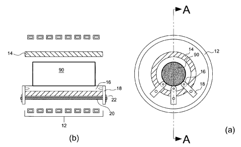
[0007] FIG. 1(a) is a side elevational view of one example of the billet
support system of the
present invention wherein adjusting elements of each support rail are
independent from each
other.
[0008] FIG. 1(b) is a cross sectional view through line A-A in FIG. 1(a).
[0009] FIG. 2(a) is a side elevational view of another example of the billet
support system of the
present invention wherein adjusting elements of each support rail utilize
common elements.
[0010] FIG. 2(b) is a cross sectional view through line B-B in FIG. 2(a).
[0011] FIG. 3 is a side elevational view of another example of the billet
support system of the
present invention wherein the support rails provide sufficient curvilinear
billet seating surfaces
for varying sizes of billets without adjustment of the support rails.
[0012] FIG. 4(a) is a side elevational view of another example of the billet
support system of the
present invention wherein the support system also serves as a thermal
insulating structure.


CA 02553697 2006-07-19
WO 2005/072215 PCT/US2005/001734
[0013] FIG. 4(b) is a cross sectional view through line C-C in FIG. 4(a).
[0014] FIG. 5(a) is a side elevational view of another example of the billet
support system of the
present invention wherein support rails are radially disposed around the
opening for a billet.
[0015] FIG. 5(b) is a cross sectional view through line D-D in FIG. 5(a).
Detailed Description of the Invention
[0016] There is shown in FIG.1(a) and FIG. 1(b) one example of the billet
support system of
the present invention. Thermal insulation 14 is generally cylindrical in shape
and is inserted
within solenoidal induction coil 12. In this non-limiting example of the
invention three rails 16
are longitudinally disposed along the interior wall of thermal insulation 14.
[0017] Each rail comprises a heat resistant material, such as a ceramic based
on silicon (Si),
aluminum (Al), oxygen and nitrogen (generally known as a "sialon" ceramic).
See U.S. Patent
No. 4,113,503 for one example of a sialon ceramic. Each rail is generally
cylindrical in shape;
however the shape of the rail is not limited to cylindrical shapes. In general
the rail is shaped to
provide a curvilinear seating surface for a billet. A hole is provided at each
end of a rail. Each
side support member 18 includes an appropriately shaped dowel to fit in the
hole. Joining
member 20 can be a threaded rod that protrudes at each end through a hole in
each of the side
support members as shown for one of the three rails in FIG. 1(b). Fasteners 22
rigidly hold
together the rectangular-shaped frame structure formed by rail 16, two side
members 18 and
joining member 20. In this example of the invention billet 90 is pushed into
the open cylinder
formed by thermal insulation 14 to make contact with and slide along portions
of the curvilinear
surfaces of the three rails. Generally coil 12 will be much closer to the
billet than
diagrammatically shown in FIG.1(a) and FIG. 1(b). Side members 18 may be
extended so that
joining member 20 is disposed external to coil 12. Alternatively joining
member 20 may be
replaced by independent fasteners associated with each side member to hold a
rail in place.
[0018] FIG. 2(a) and FIG. 2(b) illustrate another example of the billet
support system of the
present invention wherein arc-shaped joining member 24 provides a means for
adjusting the
locations of rails 16a about the inner wall of the thermal insulation. In this
non-limiting example
an arc-shaped opening in member 24 provides the adjusting means. The opening
may be
appropriately notched or marked for set alternative rail positions to
accommodate billets of
various sizes. Side members 18 for each rail are joined together as shown in
FIG. 2(a) which, in


CA 02553697 2006-07-19
WO 2005/072215 PCT/US2005/001734
this example, is similar to the method used in FIG.1(a) except for the
inclusion of arc-shaped
joining members 24. In alternative examples of the invention each side member,
in lieu of the
hole through which joining member 20 passes, may have a post passing though
the arc-shaped
opening in adjacent joining member 24 which is used to fasten the side member
to joining
member 24. For example the post may be threaded and fastened about joining
member 24 with a
bolt. In this particular example of the invention the rails are generally
hemispherical in cross
section and modified with a base curvature to conform to the curvature of the
inside wall of the
thermal insulation.
[0019] FIG. 3 illustrates another example of the billet support system of the
present invention.
In this example rails 16b are two in number and generally semielliptical in
cross section and
modified with a base curvature to conform to the curvature of the inside wall
of the open
cylinder. The broad cross sectional curvilinear billet seating surface
afforded by generally
semielliptical rails 16b provides a billet support means that can accommodate
a variety of sizes of
billets (e.g. billets 90, 90a and 90b with perimeters shown in FIG. 3) without
adjusting the
positions of rails 16b. In this example rails 16b may be permanently attached
to the thermal
insulation, integrally cast with the thermal insulation or imbedded in the
thermal insulation. In
other examples of the invention rails 16b may be provided with position
adjusting members as
illustrated in FIG. 1(a) or FIG. 2(a).
[0020] FIG. 4(a) and FIG. 4(b) illustrate another example of the billet
support system of the
present invention wherein the function of billet support is provided by a
generally
cylindrically-shaped element 26 into which a billet is insert at entrance end
26a. In this example
the entrance end is beveled or otherwise shaped to prevent jamming the billet
against the end of
element 26 as it is pushed into the element. Further the interior bottom wall
of element 26 may
deviate from true cylindrical to provide a better seating surface for the
billet as shown in
FIG. 4(a). In this example of the invention element 26 can serve both as the
means for seating
the billet inside the coil and as thermal insulating means.
[0021] FIG. 5(a) and FIG. 5(b) illustrate another example of the billet
support system of the
present invention wherein a plurality of rails 16c are radially disposed
around the opening in
which a billet is placed. In this arrangement of the invention rails 16c may
be fastened about
thermal insulation 14 as described above or partially embedded into the
thermal insulation as
shown in the figures. The exposed curvilinear surfaces of the lower rails
provide a surface for
seating a billet in and sliding a billet through the coil. The exposed
curvilinear surfaces of the


CA 02553697 2006-07-19
WO 2005/072215 PCT/US2005/001734
other rails provide a means for preventing a billet from jamming into the
interior wall of the
insulation as it is pushed through the coil. For example, as shown in FIG.
5(b) while billet 90
has substantially vertical end surfaces, billet 91, which will push billet 90
out of the coil as
billet 91 is pushed into the coil has a leading end surface that is skewed
from the vertical. In such
situations the leading end of billet 90 will have a tendency to jam against
the upper interior wall
of the thermal insulation. The exposed curvilinear surfaces of rails 16c
embedded in the upper
wall will provide a low friction surface upon which billet 90 will continue to
slide out of the coil
rather than jam in the coil.
[0022] In the above examples of the invention cylindrically-shaped thermal
insulation 14 may be
replaced by any other structure suitable for mounting of the rails, or
mounting structure, when rail
mounting is required within the induction coil. That is the rail mounting
structure may be
separate from the thermal insulation if used. Generally the thermal insulation
comprises a
substantially non-magnetic material.
[0023] The foregoing examples do not limit the scope of the disclosed
invention. The scope of
the disclosed invention is further set forth in the appended claims.

Representative Drawing
A single figure which represents the drawing illustrating the invention.
Administrative Status

For a clearer understanding of the status of the application/patent presented on this page, the site Disclaimer , as well as the definitions for Patent , Administrative Status , Maintenance Fee  and Payment History  should be consulted.

Administrative Status

Title Date
Forecasted Issue Date 2010-06-29
(86) PCT Filing Date 2005-01-20
(87) PCT Publication Date 2005-08-11
(85) National Entry 2006-07-19
Examination Requested 2009-11-03
(45) Issued 2010-06-29

Abandonment History

There is no abandonment history.

Maintenance Fee

Last Payment of $459.00 was received on 2021-12-08


 Upcoming maintenance fee amounts

Description Date Amount
Next Payment if small entity fee 2023-01-20 $253.00
Next Payment if standard fee 2023-01-20 $624.00

Note : If the full payment has not been received on or before the date indicated, a further fee may be required which may be one of the following

  • the reinstatement fee;
  • the late payment fee; or
  • additional fee to reverse deemed expiry.

Patent fees are adjusted on the 1st of January every year. The amounts above are the current amounts if received by December 31 of the current year.
Please refer to the CIPO Patent Fees web page to see all current fee amounts.

Payment History

Fee Type Anniversary Year Due Date Amount Paid Paid Date
Registration of a document - section 124 $100.00 2006-07-19
Application Fee $400.00 2006-07-19
Maintenance Fee - Application - New Act 2 2007-01-22 $100.00 2007-01-09
Maintenance Fee - Application - New Act 3 2008-01-21 $100.00 2008-01-11
Maintenance Fee - Application - New Act 4 2009-01-20 $100.00 2008-12-15
Request for Examination $800.00 2009-11-03
Maintenance Fee - Application - New Act 5 2010-01-20 $200.00 2009-12-15
Final Fee $300.00 2010-03-30
Maintenance Fee - Patent - New Act 6 2011-01-20 $200.00 2011-01-17
Maintenance Fee - Patent - New Act 7 2012-01-20 $200.00 2012-01-05
Maintenance Fee - Patent - New Act 8 2013-01-21 $200.00 2013-01-09
Maintenance Fee - Patent - New Act 9 2014-01-20 $200.00 2013-12-24
Maintenance Fee - Patent - New Act 10 2015-01-20 $250.00 2015-01-14
Maintenance Fee - Patent - New Act 11 2016-01-20 $250.00 2015-12-30
Maintenance Fee - Patent - New Act 12 2017-01-20 $250.00 2016-12-29
Maintenance Fee - Patent - New Act 13 2018-01-22 $250.00 2017-12-28
Maintenance Fee - Patent - New Act 14 2019-01-21 $250.00 2018-12-31
Maintenance Fee - Patent - New Act 15 2020-01-20 $450.00 2019-12-27
Maintenance Fee - Patent - New Act 16 2021-01-20 $450.00 2020-12-22
Maintenance Fee - Patent - New Act 17 2022-01-20 $459.00 2021-12-08
Owners on Record

Note: Records showing the ownership history in alphabetical order.

Current Owners on Record
INDUCTOTHERM CORP.
Past Owners on Record
CORDIER, JEAN-PIERRE J.A.
DOYON, GARY A.
FISHMAN, OLEG S.
HOOPER, JOHN H.
Past Owners that do not appear in the "Owners on Record" listing will appear in other documentation within the application.
Documents

To view selected files, please enter reCAPTCHA code :


To view images, click a link in the Document Description column. To download the documents, select one or more checkboxes in the first column and then click the "Download Selected in PDF format (Zip Archive)" or the "Download Selected as Single PDF" button.

List of published and non-published patent-specific documents on the CPD .

If you have any difficulty accessing content, you can call the Client Service Centre at 1-866-997-1936 or send them an e-mail at CIPO Client Service Centre.


Document
Description 
Date
(yyyy-mm-dd) 
Number of pages   Size of Image (KB) 
Abstract 2006-07-19 2 69
Claims 2006-07-19 3 124
Drawings 2006-07-19 5 69
Description 2006-07-19 5 253
Representative Drawing 2006-07-19 1 14
Cover Page 2006-09-22 1 42
Claims 2009-11-03 3 144
Description 2009-11-03 5 255
Representative Drawing 2010-06-04 1 14
Cover Page 2010-06-04 1 44
Fees 2007-01-09 1 40
Assignment 2006-07-19 11 336
Fees 2008-01-11 2 85
Fees 2008-12-15 1 38
Correspondence 2010-03-30 1 38
Prosecution-Amendment 2009-11-03 9 332
Fees 2011-01-17 1 28
Correspondence 2012-06-28 4 66