Note: Descriptions are shown in the official language in which they were submitted.
CA 02553783 2011-05-02
SYSTEM AND METHOD FOR SELECTIVE COMPONENT CRACKING
TO MAXIMIZE PRODUCTION OF LIGHT OLEFINS
10 BACKGROUND
1. Field of the Invention
The present invention relates to a system and method for fluid catalytic
cracking (FCC) to maximize the yield of light olefins.
2. Background of the Art
The fluid catalytic cracking (FCC) process is commonly used to crack
high boiling petroleum fractions by contacting the high boiling feed with
fluidized catalyst particles in a riser to produce primarily motor fuels. It
also
produces a certain amount of light hydrocarbons such as C3 and C4 compounds
and light olefins such as propylene and butylenes. However, the relative
demand for the light olefins has been increasing. Therefore, the FCC process
needs to be adapted to produce more of these light olefins.
For example, U.S, Patent No. 5,997,728 discloses a catalyst system for
maximizing light olefin yields in FCC. The process employs a catalyst with
large
amounts of shape selective cracking additive.
U.S. Patent No. 6,069,287 discloses a process for selectively producing
C2-C4 olefins in a FCC process from a thermally cracked naphtha stream. The
naphtha stream is contacted with a catalyst containing from about 10- to 50
CA 02553783 2006-07-17
WO 2005/073347 PCT/US2005/001724
wt% of crystalline zeolite having an average pore diameter of less than about
0.7
nanometers.
U.S. Patent No. 6,093,867 discloses a process for selectively producing
C3 olefins from a catalytically cracked or thermally cracked naphtha stream.
The naphtha stream is introduced into a process unit comprised of a reaction
zone, a stripping zone, a catalyst regeneration zone, and fractionation zone.
The naphtha feed stream is contacted in the reaction zone with a catalyst
containing from about 10 to 50 wt. % of a crystalline zeolite having an
average
pore diameter less than about 0.7 nanometers at reaction conditions which
include temperatures ranging from about 500 to 650 C. and a hydrocarbon
partial pressure from about 10 to 40 psia. Vapor products are collected
overhead and the catalyst particles are passed through the stripping zone on
the way to the catalyst regeneration zone. Volatile compounds are stripped
with
steam in the stripping zone and the catalyst particles are sent to the
catalyst
regeneration zone where coke is burned from the catalyst, which is then
recycled to the reaction zone. Overhead products from the reaction zone are
passed to a fractionation zone where a stream of C3's is recovered and a
stream
rich in C4 and/or Cs olefins is recycled to the stripping zone.
Other patents describing FCC processes for producing higher yields of
light olefins include U.S. Patent Nos. 6,106,697, 6,118,035, 6,313,366 and
6,538,169, for example.
There is yet a need for a FCC system and method that is able to
maximize production of light olefins more efficiently and selectively.
SUMMARY
A process for the fluid catalytic cracking of hydrocarbons is provided
herein. The process comprises contacting a feed of heavy/high boiling
2
CA 02553783 2006-07-17
WO 2005/073347 PCT/US2005/001724
hydrocarbons with a particulate catalyst in a reaction zone under fluidized
catalytic cracking conditions to convert at least some of the hydrocarbons to
light olefins having from 3 to 4 carbon atoms, conveying spent catalyst and a
gaseous fluid containing the light olefins and other products of conversion to
a
cyclone separation system within a containment/ separation vessel, the
containment/ separation vessel enclosing an interior space having a stripping
region and an upper region in which the cyclone separation system that is
directly connected to the riser reaction zone is positioned, wherein the
cyclone
separation system includes a first cyclone having an interior first pressure
and
said stripping region having a second pressure, the interior first pressure
being
at least about 0.05 psi lower than the stripping region second pressure. The
gaseous hydrocarbon products are separated from the catalyst particles in the
cyclone separation system and flow to the product separation or fractionation
section downstream of the separation vessel. The catalyst particles are then
transferred to the stripping region. The spent catalyst particles are
contacted
with a stripping gas to remove entrained hydrocarbons, the stripping gas with
entrained hydrocarbons being moved through the cyclone and through the exit
port. The stripped catalyst particles are then transferred to a regeneration
zone for decoking, and the decoked or regenerated catalyst particles are then
transferred back to the reaction zone.
BRIEF DESCRIPTION OF THE DRAWINGS
Various embodiments are described below with reference to the drawings
wherein:
FIG. 1 is a schematic illustration of reactions occurring in an FCC
process;
3
CA 02553783 2006-07-17
WO 2005/073347 PCT/US2005/001724
FIG. 2 is a diagrammatic illustration of an FCC system employing the
invention employing a single riser reaction zone;
FIG. 3 is a diagrammatic illustration of an alternative FCC system
employing dual riser reaction zones;
FIG. 4 is a graph illustrating pressure differential versus product
recovery efficiency; and,
FIG. 5 is a graph illustrating C3H6 selectivity versus feed conversion.
DETAILED DESCRIPTION OF PREFERRED EMBODIMENT(S)
The FCC process of the invention employs a catalyst in the form of very
fine solid particles that are fluidized in a reaction zone which is in the
form of a
vertical riser reactor. The feed is contacted with the catalyst at the bottom
of
the vertical riser reactor and lifted with the catalyst to the top of the
riser
reactor, as described more fully below.
The feed is a relatively heavy hydrocarbon fraction having a relatively
high boiling point and/or molecular weight. The term "relatively heavy" as
used
herein refers to hydrocarbons having five or more carbon atoms, typically more
than 8 carbon atoms. For example, the feed can be a naphtha, vacuum gas oil
or residue. Typically, the feed is a petroleum fraction having a boiling range
of
from about 250 C to about 625 C.
The catalyst used in this invention can be any catalyst commonly used in
FCC processes. These catalysts generally consist of high activity crystalline
alumina silicates. The preferred catalyst components are zeolites, as these
exhibit higher intrinsic activity and resistance to deactivation. Typical
zeolites
include ZSM-X, ZSM-Y, ZSM-5, ZSM-11, ZSM-12, ZSM-23, ZSM-35, ZSM-38
and ZSM-48. A more preferred catalyst of the present invention is based upon
Ultrastable Y (USY) zeolite with higher silica to alumina ratio. The catalysts
can
4
CA 02553783 2006-07-17
WO 2005/073347 PCT/US2005/001724
be used alone or in combination with zeolites having a shape selective
pentasil
structure, such as ZSM-5, that convert larger linear hydrocarbon compounds to
smaller ones, especially larger olefins to smaller olefins. Non-zeolite
catalysts
such as amorphous clays or inorganic oxides can also be employed.
The present invention maximizes selectivity of the light olefins (C3-C4
olefins) by means of the FCC unit hardware design, operating conditions and
catalyst formulation. The hardware design, operating conditions, and catalyst
formulation are tailored to achieve kinetic and thermodynamic effects which
favor the production of olefins. The catalyst formulation or the mixture of
catalysts used in this invention is selected from the family of catalysts
described above, such that the catalysts activity for catalytic conversion is
maximized along with maximization of conversion of larger molecular weight
olefins to smaller molecular weight olefins, while the tendency for
resaturation
of the light olefins thus produced is minimized.
Referring to FIG. 1, various reactions which occur in FCC are
diagrammatically illustrated. Paraffins are cracked to produce olefins.
Olefins,
however, can react to produce naphthenes through cyclization reactions,
smaller olefins through cracking reactions, and paraffins through hydrogen
transfer. Olefins can also undergo isomerization. The naphthenes can be
converted to olefins or cycloolefins. Aromatics can be produced by
dehydrogenation of cycloolefins. The aromatics, in turn, can be cracked, or
can
undergo dehydrogenation and/or alkylation to produce heavy coke, and
polycyclic or heterocyclic aromatics.
The desired reaction is the conversion of paraffins to light olefins, which
is characterized by a faster reaction rate than the undesired secondary
reactions. Thus, by limiting the reaction time, one can terminate the
undesired
chain reactions quickly after the olefin production has taken place. The quick
5
CA 02553783 2006-07-17
WO 2005/073347 PCT/US2005/001724
termination of the side reactions is achieved by having a very short residence
time in the riser reactor and, more importantly, quick and efficient
separation of
the reaction products from the catalyst at the termination of the reaction at
the
end of the riser reactor.
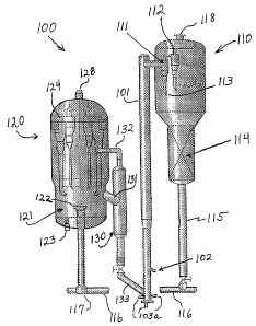
Referring now to FIG. 2, a FCC system 100 is illustrated for the selective
component cracking of the invention. The system 100 includes a vertical riser
reactor 101. The initial feed is introduced into the riser 101 through
injectors
102. Regenerated catalyst mixes with the feed and both are carried upward in
the riser wherein the cracking reaction occurs.
Regenerated catalyst typically enters the riser at a temperature of about
650 C to 760 C and the cracking reaction in the riser usually occurs at a
temperature in the range of about 500 C to about 600 C.
Low hydrocarbon partial pressure in the riser favors light olefin
production. Generally, the riser pressure is set at about 10 to 25 psig, with
a
hydrocarbon partial pressure of about 3 to 10 psig. Steam or other dry gas may
be used as a diluent to achieve the lower hydrocarbon partial pressure.
In order to maximize the production of light olefins, certain selected
components of the product of the first pass conversion are recycled to the
riser
reactor for further cracking. This mode of operation is termed selective
component cracking ("SCC"). The selected component to be recycled and re-
cracked could be a range of materials such as higher carbon number olefins, or
straight run products from other conversion units. The selected components
are not mixed with the fresh feed at injector 102. Rather, these components
are
injected separately through a set of injection points in the riser reactor
system
where the conditions are ideal for cracking these components. The lighter
selected components are injected through multiple injectors 103a upstream of
6
CA 02553783 2011-05-02
the fresh feed injector 102 and at points where these components can
thoroughly mix or contact the high activity, high temperature catalyst.
Optimization of the reaction residence time is an important feature of the
invention. Longer residence time allows for more thorough cracking, but also
increases the secondary reactions that reduce the yield of light olefins.
Preferred residence times range from 0.5 to 10.0 seconds, more preferably 1.0
to 5.0 seconds and most preferably 1.0 to 3.0 seconds.
The reactor effluent exits at the top of riser 101 and enters separator
vessel 110 and is introduced into at least one, and preferably two, cyclone
separators. The gas and solids are mostly separated in first cyclone 111, and
the overhead from first cyclone 111 is directed to second cyclone 112 for
final
separation. The solids drop out through diplegs 113 into the stripper 114. The
gases are sent out through outlet 118 to a main, or primary, fractionation
column and downstream product separation system where various product
fractions are separated through a number of fractionation steps. Some of the
products are recycled back to the reaction, as mentioned above.
A unique feature applied in this invention that helps to preserve the yield
of light olefins formed in the riser reaction zone is that the cyclone 111
operates
at a lower pressure than the interior of the vessel 110. This pressure
differential is maintained by having the gases from the stripper vessel 114
pass
through an orifice in the roof of the cyclone 111, as described, for example,
in
U.S. Patent No. 5,248,411. The
lower pressure in cyclone 111 provides complete separation of the reacting
hydrocarbons from the catalyst so as to quickly terminate secondary chain
reactions, and thereby preserves the yield of light olefins. Referring now to
FIG.
4, it can be seen that when cyclone 111 are operating at a negative pressure,
i.e., when the pressure in cyclone 11 1 is lower than the pressure in vessel
110,
7
CA 02553783 2006-07-17
WO 2005/073347 PCT/US2005/001724
the product recovery efficiency is almost 100%. When the pressure differential
is zero, i.e., when vessel 110 and cyclone 111 are at the same pressure, the
efficiency of product recovery is 97%. When cyclone 111 is at a pressure only
0.4 psi higher than the pressure in vessel 110, the product recovery
efficiency
drops to below 80%. The lower cyclone pressure prevents the reacting gases
from flowing down with the separated catalyst solids through the diplegs and
into the interior of vessel 110. Otherwise, the reacting gases would remain in
contact with the catalyst and the slower secondary reactions would have
additional time to proceed and reduce selectivity for olefins.
During the course of reaction in the riser reactor 101, the catalyst
particles become laden with predominantly carbonaceous material termed
"coke" that is a by-product of the cracking reactions. The catalyst particles
also
contain hydrocarbons in their pores and entrain some hydrocarbons after
separation from the vapor phase in the cyclones 111 and 112. The coke
deposits deactivate the catalyst by blocking active access of the reacting
species
to the active sites of the catalyst. The catalyst activity is restored by
combusting
the coke with an oxygen-containing gas in a regeneration vessel 120. However,
before the regeneration step, the catalyst is stripped with steam in the
stripping
vessel 114 to remove the accompanying hydrocarbon vapors that would,
otherwise, burn in the regenerator and represent loss of the valuable
products.
Referring now again to FIG. 2, the catalyst particles which flow out of the
cyclones 111 and 112, fall into the stripping section 114 of vessel 110
wherein
the particles are separated of any entrained or adsorbed hydrocarbons by
conventional countercurrent contact with steam. The stripper internals are
designed to maximize contact time and surface area for mass transfer between
the fluidized catalyst phase and the stripping steam phase. The stripped
catalyst particles then drop through downflow line 115 and are carried by
8
CA 02553783 2006-07-17
WO 2005/073347 PCT/US2005/001724
transfer line 116 to a square bend 117 from which they are carried upward into
the middle of fluid bed 121 in regenerator 120 through outlet 122. Uniform
distribution of the coke laden catalyst in the center of the regeneration bed
121
is important for regaining catalyst activity and surface area. The square bend
transfer line possesses a unique configuration that eliminates erosion
problems
associated with other designs for similar dilute phase catalyst transfer, such
as
the use of an elbow for the horizontal to vertical turn for the transport of
the
spent catalyst. This square bend configuration results in trouble-free
introduction of the spent catalyst into the center of the regenerator for
uniform
and thorough regeneration of the catalyst, so that catalyst activity for
desired
reactions is maximized for the production of light olefins.
Oxygen containing gas, e.g., air, is introduced in the regenerator 120
through inlet 123 under bed 121 to fluidize the bed and to oxidize coke
deposits
on the catalyst particles through combustion. Combustion gas inlet 123 is
representative of a plurality of such distributors such that the oxygen
containing gas is spread uniformly across the bed area so as to match the
distribution of the spent catalyst from the outlet 122. The exhaust resulting
gas is sent through cyclones to separate out any catalyst particles and then
through outlet 128.
Regenerated (i.e., decoked) catalyst particles are then withdrawn through
line 131 and flow down through regenerated catalyst standpipe 130 and via
regenerated catalyst feed line 133, into the riser 101. Line 132 serves as a
vent
to facilitate downflow of the catalyst particles.
Referring now to FIG. 3, an alternative embodiment 200 of the FCC
system is illustrated. System 200 is similar to system 100 except that it
includes a second riser reactor 201. Initial feed is introduced into riser 201
through injector 202. Selected components recycled from the first pass
9
CA 02553783 2012-03-22
conversion can be introduced into the riser 201 at injector 203a. Regenerated
catalyst from regenerated catalyst standpipe 130 is introduced into riser 201
via regenerated catalyst feed line 233. The effluent from riser reactor 201
exits
at the top of the riser and is introduced into a first cyclone 211. The
overhead
from the first cyclone is introduced into a second cyclone 212. The solids
drop
through the cyclone diplegs into the stripping region 114. As described above,
the pressure inside cyclones 211 and 212 is less than the pressure within
stripping region 114.
Referring now to Fig. 5, the relationship between propylene selectivity
and feed conversion with parameters of hydrocarbon partial pressure is
illustrated. The graph shows the advantage of operating the FCC process at a
lower hydrocarbon partial pressure. For hydrocarbon partial pressure X,
wherein X can range from about 10 psig to about 25 psig, it can be seen that a
decrease of hydrocarbon partial pressure of 5 psig (X-5 psi) results in
dramatically improved selectivity to propylene. Accordingly, it is a feature
of the
invention to conduct the FCC process at a hydrocarbon partial pressure of no
more than about 10 psig, preferably no more than about 7 psig and more
preferably no more than about 5 psig.
The scope of the claims should not be limited by the preferred embodiments set
forth
herein, but should be given the broadest interpretation consistent with the
description as a
whole.