Note: Descriptions are shown in the official language in which they were submitted.
CA 02553956 2006-07-19
PCT/AU2004/000064
Received 1 December 2004
- 1 -
ELECTRICAL CONNECTION DEVICE
Field of the Invention
The present invention broadly relates to an
electrical connection device for a machine, reeling or
trailing cable. Throughout this specification the term
"machine cable" is used for any machine, reeling or
trailing cable that is arranged for delivery of power to
mobile machinery such as large machinery in petroleum or
mining industry
Background of the Invention
Machine, reeling or trailing cables are typically
used to provide an electrical connection for mobile
electrical machines. For example, in the mining or
petroleum industry often large electrical machinery is
used and each machine, reeling or trailing cable may have
to provide power in the order of a few hundred kilowatts.
Typically such power is delivered with a voltage of one or
more kilovolts. The cables used to deliver the electricity
are usually formed from a plurality of bunches which are
connected using electrical connection devices including
sockets and pins.
Figure 1 shows a schematic cross-sectional
representation of a typical prior art electrical
connection device 10. The device 10 comprises a housing 12
in which a socket 14 and a pin 16 engage. The socket 14 is
metallic and includes six fingers 18 and a compression
spring 19 is arranged to press the fingers 18 and/or tips
of the fingers against the pin 16 to establish an
electrical connection. However, the compression spring 19
may loose tension over time, in particular when the
Amended Sheet
IPEA/AU
CA 02553956 2006-07-19
PCT/AU2004/000064
Received 1 December 2004
2 -
electrical connection device is exposed to a heat source
or when large currents flow though the device which may
result in heat development.
Summary of the Invention
The present invention provides in a first aspect an
electrical connection device arranged for connection to a
machine cable, the device comprising:
a pin and a socket, each having engagement surfaces
and one of the pin and the socket having a further surface
that forms a wedging surface for the device, the pin and
the socket being moveable relative to each other from a
released position to an engaged position in which the
engagement surfaces are engaged to form an electrical
contact and
a wedge portion arranged to impart a force on the
wedging surface on movement to the engaged position,
wherein the pin and the socket are arranged so that
the engagement surfaces move into opposing relationship on
movement to the engaged position and the force imparted on
the wedging surface biases one of the opposing engagement
surfaces against the other engagement surface.
As a portion of one of the pin and the socket is
wedged against a portion of the other one of the pin and
the socket, the electrical connection device has the
advantage that a firm electrical connection can be
established without a compression spring. Further, the
engagement may be stronger than an electrical connection
that may be achieved with typical prior art devices.
The electrical connection device typically is
arranged for delivery of a power of a few hundred
kilowatts. Further, the electrical connection device
Amended Sheet
IPEA/AU
CA 02553956 2006-07-19
r PCT/AU2004/000064
Received 1 December 2004
- 3 -
typically is arranged for delivery of power having an
associated voltage of one or more kilovolts.
The wedge portion typically is not integrally formed
with the pin or the socket and may comprise a material
other than that of the pin or the socket. For example, the
wedge portion may be a part that is separable from the pin
or the socket. The wedge portion may also be adhered to a
portion of the pin or the socket.
At least one of the pin and the socket typically has
a marginal portion that includes the wedging surface and
that has at least one gap which expands or reduces when
the wedge portion imparts a force on the marginal portion
so that the outer perimeter of the marginal portion
expands or compresses.
The marginal portion typically is a part of the
socket. In this case the wedge portion may be arranged
such that, when the pin and the socket are moved relative
to each other to the engaged position, the wedge portion
compresses the marginal portion against the pin whereby
the pin and the socket engage to establish the electrical
connection.
The socket typically is of a longitudinal shape and
the marginal portion typically is an end-portion of the
socket.
The wedge portion may comprise a flexible material
that typically is resilient. The flexible material may be
a polymeric material and such as a rubber. The wedge
portion typically comprises an electrically conductive
material such as an electrically conductive polymeric
material.
As discussed above, because of the wedge portion a
firm electrical connection may be established without a
Amended Sheet
IPEA/AII
CA 02553956 2006-07-19
PCT/AU2004/000064
Received 1 December 2004
4 -
compression spring. If the wedge portion comprises the
flexible material, such as the polymeric material,
disconnecting the pin and the socket, which typically are
composed of a metallic material, is facilitated.
For example, the pin and the socket may be of a
generally round cross-section. The socket and the pin may
be, when in the engaged position, surrounded by a sleeve.
In this case the pin typically is secured in the sleeve.
The wedge portion may be provided in form of a ring-
like portion positioned such that, when the pin and the
socket are moved relative to each other towards the
engaged position, the wedge portion wedges the end-portion
of the socket against the pin. This has the advantage that
the socket may be fitted over the pin without much
frictional resistance and only when the pin and the socket
have been moved relative to each other such that the
engaged position is almost reached, the wedge portion
wedges the end-potion of the socket towards the pin and
therefore imposes greater friction.
The socket may have an inner surface that has a
substantially uniform diametrical dimension throughout its
length. However, the inner surface typically has a tapered
region. In this case the tapered region may separate a
region of a smaller interior diameter from a region of a
larger interior diameter. The region of the smaller
interior diameter typically comprises the engagement
surface and is arranged so that, when the wedge portion
imparts a force on the wedging surface, the region of
smaller interior diameter frictionally engages with the
engagement surface of the pin and typically is not
positioned at an end of the inner surface.
The pin may have an outer surface that is of a
substantially uniform diametrical dimension.
Amended Sheet
IPEA/AU
CA 02553956 2006-07-19
PCT/AU2004/000064
Received I December 2004
- 5 --
Alternatively, the outer surface of the pin may have a
tapered region. The tapered region may separate a region
of a larger exterior diameter from a region of a smaller
exterior diameter. In this case the region of the larger
exterior diameter typically comprises the engagement
surface and is arranged so that, when the wedge portion
imparts a force on the wedging surface, the region of
larger exterior diameter frictionally engages with the
engagement surface of the socket and typically is not
positioned at an end of the outer surface.
In a specific embodiment of the present invention,
the socket has an inner surface that has a tapered region
and a region of smaller interior diameter. In this
embodiment the pin has an outer surface that has a
substantially uniform diametrical dimension. In this case
the region of the smaller interior diameter typically is
positioned such that, when the wedge portion wedges the
end-portion of the socket against the pin, the contact
area between pin and socket increases to predetermined
size. In electrical connection devices known in the prior
art (see Figure 1), the socket may contact the pin at the
tip of the fingers of the socket and the electrical
contact area may be relatively small. In the above-
described specific embodiment the tapered shape of the
inner surface of the socket or of the outer surface of the
pin, respectively, may overcome this disadvantage and may,
together with the wedging function of the wedge portion,
result in a relatively larger contact area between the pin
and the socket.
The gap typically is one of a plurality of
longitudinal gaps that split the socket into three or more
fingers which typically are substantially equal.
In another embodiment the device comprises at least
Amended Sheet
IPEA/AU
CA 02553956 2006-07-19
PCT/AU2004/000064
Received 1 December 2004
-6-
two wedge portions and both the first and the second part
have wedging surfaces, the wedge portions being arranged
to impart a force on respective wedging surfaces to bias
respective opposing engagement surfaces against each
other.
The present invention provides in a second aspect a
method of connecting a pin and a socket of an electrical
connection device arranged for connection to a machine
cable, the method comprising the steps of
moving the pin and the socket relative to each other
towards a position at which the pin and the socket are
engaged, the pin and the socket having engagement surfaces
and at least one of the pin and the socket having an
additional wedging surface, the pin and the socket being
arranged so that during engagement the engagement surface
of the pin opposes the engagement surface of the socket
and
wedging a wedging portion to impart a force on the
wedging surface
wherein the pin and the socket are arranged so that
the force causes pressing of one of the opposing
engagement surfaces against the other engagement surface
to establish an electrical contact.
The present invention provides in a third aspect an
electrical connection arranged for connection to a machine
cable, the device comprising:
a pin and a socket, the pin and the socket being
moveable relative to each other from a released position
to an engaged position, at least one of the pin and the
socket having a marginal portion that is-compressible or
expandable in at least one direction and
a wedge portion arranged such that, when the pin and
Amended Sheet
IPEAIAU
CA 02553956 2011-02-28
7 -
the socket are moved relative to each other towards the engaged
position, the wedge portion expands or compresses the marginal
portion whereby the pin and the socket engage.
The present invention provides in a fourth aspect, an
electrical connection device arranged for connection to a
machine cable, the device comprising: a pin and a socket, each
having engagement surfaces and one of the pin and the socket
having a further surface that forms a wedging surface for the
device, the pin and the socket being moveable relative to each
other from a released position to an engaged position in which
the engagement surfaces are engaged to form an electrical
contact and a wedge portion arranged to impart a force on the
wedging surface on movement to the engaged position, wherein the
pin and the socket are arranged so that in use the wedge portion
is pressed between the pin and the socket so as to produce a
force on the wedging surface and the engagement surfaces move
into opposing relationship on movement to the engaged position
and the force imparted on the wedging surface biases one of the
opposing engagement surfaces against the other engagement
surface; and wherein the socket has an inner surface or the pin
has an outer surface that has a curved shape that, together with
the wedging function of the wedging portion, results in bending
whereby a contact area between the pin and the socket at an apex
of the curvature is increased; and wherein the electrical
connection device is arranged for delivery of a power of a few
hundred kilowatts having an associated voltage of one or more
kilovolts, and wherein the wedging portion comprises a material
other than the pin or the socket and that is flexible.
A specific embodiment will now be described, by way of
example only, with reference to the accompanying drawings.
CA 02553956 2011-02-28
- 7a -
Brief Description of the Drawings
Figure 1 shows a schematic cross-sectional representation
of an electrical connection device (prior art),
Figure 2 shows a schematic cross-sectional representation
of an electrical connection device according to a specific
embodiment,
Figure 3 shows another schematic cross-sectional
representation of the electrical connection device,
Figure 4 shows a schematic representation of a part of the
electrical connection device ((a) end view and (b) cross-
sectional view) and
Figure 5 shows a schematic representation of a socket that
forms a part of the electrical connection device ((a) side view
and (b) end view).
Detailed Description of a Specific Embodiment
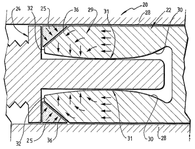
Referring to Figures 2 to 5, the electrical connection
device 20 is now described. Figure 2 shows the electrical
connection device 20 including a socket 22 connected to a pin
24. In this embodiment, the pin 24 and the socket 22 are
arranged for connection to a thimble (not shown) and the
thimbles are arranged to receive a machine cable. Socket 22, pin
24 and thimbles are located
F_ CA 02553956 2006-07-19
PCT/AU2004/000064
Received 1 December 2004
- 8 -
in a housing 28. The socket 22, the pin 24 and the
thimbles are composed of a metallic material. The device
20 comprises a wedge portion 25 that has a ring-like shape
and is composed of a flexible material such as a polymeric
material. In this embodiment the flexible material is an
electrically conductive polymeric material. Figure 4 shows
the wedge portion 25 as viewed from the top (a) and in
cross-section (b).
The socket 22 has an inner surface 30 arranged to
receive the pin 24. The inner surface 30 of the socket 22
has a tapered region which is shaped such that there is a
region 31 of smallest interior diameter.
Figure 5 shows the socket 22 ((a) side-view, (b) end-
view). The socket has an end-portion 29 that is
compressible and that has four fingers 32. The fingers 32
are separated by gaps 34 and each finger 32 has an angled
region 36.
In this embodiment, the wedge portion 25 is designed
as an insert for the pin 24. Alternatively, the wedge
portion 25 may also be attached to angled surface 36. For
example, the wedge portion 25 may be glued to the angled
surface 36 or otherwise adhered. A wedging force is in use
imparted on the angled surface 36 because the wedge
portion 25 is enclosed by the angled surface 36, a
shoulder of the pin 24 and the housing 28. Consequently,
the wedge portion will squeeze the fingers 32 of the
socket 22 towards the pin 24.
The pin 24 and socket 22 are moveable relative to
each other by moving the socket 22 relative to the pin 24
and the housing.28. The pin 24 is secured in the housing
28. When the socket has been moved into the housing 28 and
over the pin 24, as shown in Figures 2 and 3, the angled
region 36 will be in contact with the ring-like wedge-
Amended Sheet
IPEA/AU
CA 02553956 2006-07-19
PCT/AU2004/000064
Received 1 December 2004
- 9 -
portion 25. The wedge-portion 25 wedges the angled regions
36 of the fingers 32 inwardly such that a firm electrical
contact is established between the inner surface 30 of the
socket 22 and the pin 24. Arrows in Figure 3 schematically
indicate mechanical forces during the wedging process.
Because the socket 22 has a tapered inner surface and the
fingers 32 of the socket 22 are flexible, the fingers 32
will slightly bend inwardly under the wedging force and
consequently the contact area between the pin 24 and the
socket 22 will increase. In a variation of the embodiment
shown in Figure 2, the socket 22 comprise a region of
thinner outer diameter that surrounds the region of
smallest interior diameter 31 which will increase the
flexibility of the fingers 32 of the socket 22.
Although the invention has been described with
reference to particular examples, it will be appreciated
by those skilled in the art that the invention may be
embodied in many other forms. For example, in an
alternative to the embodiment shown in Figure 3, the pin
24 may have an outwardly curved surface and the socket 22
may have a straight bore arranged to receive the pin. In
this case the wedge portion 25 would bend the fingers 32
of the socket 22 inwardly about the apex of the curvature
of the pin 22. In addition, it is to be appreciated that
alternatively the socket 22 can be secured in housing 28
and the pin 24 is arranged to be moveable relative to the
housing 28 and the socket 22. In this case the wedge
portion 25 can, for example, be provided in form of an
insert for the housing 28 that is received at the angled
surface 36 of the socket 22. Further, in an alternative
embodiment the inner surface of the socket may be straight
and the pin may have an outer surface that is also
straight. Further, the pin may include an end-portion that
Amended Sheet
IPEA/AII
CA 02553956 2006-07-19
PCT/AU2004/000064
Received I December 2004
1.0 --
is expandable and arranged to expand when the socket is
moved over the pin. In this case the end-portion of the
pin may include fingers and a wedge-portion may be
centrally located at the bottom part of the inner surface
of the socket and arranged to wedge the fingers of the pin
outwardly against the inner surface of the socket. The
device may also comprise two or more wedge portions and
both the socket and the pin may have wedging surfaces. The
wedge portions may be arranged to impart a force on
respective wedging surfaces to bias respective opposing
engagement surfaces of the pin and the socket against each
other.
Amended Sheet
IPEAIAU