Language selection

Search

Patent 2554034 Summary

Third-party information liability

Some of the information on this Web page has been provided by external sources. The Government of Canada is not responsible for the accuracy, reliability or currency of the information supplied by external sources. Users wishing to rely upon this information should consult directly with the source of the information. Content provided by external sources is not subject to official languages, privacy and accessibility requirements.

Claims and Abstract availability

Any discrepancies in the text and image of the Claims and Abstract are due to differing posting times. Text of the Claims and Abstract are posted:

  • At the time the application is open to public inspection;
  • At the time of issue of the patent (grant).
(12) Patent Application: (11) CA 2554034
(54) English Title: FLEXIBLE NOZZLE MIXING BURNER COMPRISING A SWIRL CHAMBER
(54) French Title: BRULEUR SOUPLE A FILETS PARALLELES COMPORTANT UNE CHAMBRE A TOURBILLONS
Status: Dead
Bibliographic Data
(51) International Patent Classification (IPC):
  • F23D 14/24 (2006.01)
  • F23D 14/70 (2006.01)
(72) Inventors :
  • HAECKH, VOLKER (Germany)
  • KULKIES, ANDREAS (Germany)
(73) Owners :
  • LINDE AKTIENGESELLSCHAFT (Germany)
(71) Applicants :
  • LINDE AKTIENGESELLSCHAFT (Germany)
(74) Agent: KIRBY EADES GALE BAKER
(74) Associate agent:
(45) Issued:
(86) PCT Filing Date: 2005-01-14
(87) Open to Public Inspection: 2005-08-04
Availability of licence: N/A
(25) Language of filing: English

Patent Cooperation Treaty (PCT): Yes
(86) PCT Filing Number: PCT/EP2005/000332
(87) International Publication Number: WO2005/071314
(85) National Entry: 2006-07-19

(30) Application Priority Data:
Application No. Country/Territory Date
10 2004 003 343.9 Germany 2004-01-22

Abstracts

English Abstract


The invention relates to an externally mixing burner comprising a burner head
(2), at least one fuel gas pipe (3), and at least one pipe (4) for an oxygen-
containing gas. The burner head is provided with outlets from the fuel gas
pipe and from the pipe for the oxygen-containing gas. The inventive burner is
characterized in that gas supply tubes (6, 7) for fuel gas and oxygen-
containing gas are provided, each of which is connected to a source of fuel
gas or oxygen-containing gas and at least one of which eccentrically extends
into a swirl chamber (8, 9) that is mounted between the gas supply tube and
the fuel gas pipe and/or between the gas supply tube and the pipe for oxygen-
containing gas. The invention further relates to a method for operating an
externally mixing burner comprising at least one fuel gas pipe and at least
one pipe for oxygen-containing gas through which fuel gas or oxygen-containing
gas flows to the burner head. Said method is characterized in that the fuel
gas and/or the oxygen-containing gas is/are eccentrically delivered into a
swirl chamber in which a rotational flow is impressed on the fuel gas or the
oxygen-containing gas while the fuel gas or the oxygen-containing gas is fed
to the fuel gas pipe or the pipe for oxygen-containing gas after being
discharged from the swirl chamber.


French Abstract

L'invention concerne un brûleur à mélange externe comprenant une tête de brûleur, au moins un tuyau pour un gaz combustible, et au moins un tuyau pour un gaz oxygéné. Selon l'invention, la tête de brûleur comporte des ouvertures de sortie du tuyau pour le gaz combustible ainsi que du tuyau pour le gaz oxygéné. Le brûleur selon l'invention est caractérisé en ce que des conduites d'amenée de gaz sont prévues pour le gaz combustible et pour le gaz oxygéné et sont respectivement reliées avec une source de gaz combustible et une source de gaz oxygéné, au moins une desdites conduites d'amenée de gaz menant de manière excentrique à une chambre à tourbillons montée entre la conduite d'amenée de gaz et le tuyau pour le gaz combustible et/ou entre la conduite d'amenée de gaz et le tuyau pour le gaz oxygéné. Cette invention concerne en outre un procédé pour faire fonctionner un brûleur à mélange externe comportant au moins un tuyau pour un gaz combustible et au moins un tuyau pour un gaz oxygéné à travers lesquels le gaz combustible ou le gaz oxygéné circule vers la tête de brûleur. Le procédé selon l'invention est caractérisé en ce que le gaz combustible et/ou le gaz oxygéné est/sont introduit(s) de manière excentrique dans une chambre à tourbillons dans laquelle le gaz combustible ou le gaz oxygéné est animé d'un mouvement tourbillonnant, tandis que le gaz combustible ou le gaz oxygéné est introduit dans le tuyau pour le gaz combustible ou le tuyau pour le gaz oxygéné, à sa sortie de la chambre à tourbillons.

Claims

Note: Claims are shown in the official language in which they were submitted.


7
Claims
1. Externally mixing burner (1) having a burner head (2), at least one
combustion gas tube
(3) and at least one tube (4) for an oxygen-containing gas, whereby the burner
head (2)
has outlet openings out of the combustion gas tube (3) and out of the tube (4)
for the
oxygen-containing gas, characterized in that gas inlet lines (6, 7) are
provided for the
combustion gas and for oxygen-containing gas, each being connected to a source
for
combustion gas and/or for oxygen-containing gas, respectively, and of these,
at least one
gas inlet line (6, 7) opening eccentrically into a swirl chamber (8, 9), which
is arranged
between the gas inlet line (6) and the combustion gas tube (3) and/or between
the gas
inlet line (7) and the tube (4) for oxygen-containing gas.
2. Burner (1) according to Claim 1, characterized in that at least one of the
gas inlet lines (6,
7) is divided into two lines (6a, 6b, 7a, 7b) upstream of the swirl chamber
(8, 9), whereby
one of these lines (6a, 7a) opens eccentrically into the swirl chamber (8, 9)
and the other
of these lines (6b, 7b) opens directly into the combustion gas tube (3) and/or
into the tube
(4) for oxygen-containing gas.
3. Burner (1) according to Claim 1 or 2, characterized in that valves (10, 11,
12, 13) are
provided in the gas inlet lines (6, 7), in particular valves (10, 11, 12, 13)
being provided
in the part of the gas inlet lines (6, 7) in which at least one gas inlet line
(6, 7) is already
divided into two lines (6a, 6b, 7a, 7b), and a control unit or regulating unit
is available,
controlling or regulating the degrees of opening of the valves (10, 11, 12,
13), so that the
shape of the flame of the burner (1) is adjustable.
4. Burner (1) according to one of Claims 1 through 3, characterized in that
the valves
(10, 11, 12, 13) are designed as solenoid valves (10, 11, 12, 13).
5. Burner (1) according to one of Claims 1 through 4, characterized in that
the swirl
chamber (8, 9) has a circular cross section in a section perpendicular to the
longitudinal
axis of the combustion gas tube (3).


6. Burner (1) according to Claim 5, characterized in that the gas inlet line
(6, 7, 6a, 7a)
opens tangentially into the swirl chamber (8, 9).

7. Method for operating an externally mixing burner (1) having at least one
combustion gas
tube (3) and at least one tube (4) for oxygen-containing gas, through which
combustion
gas and/or oxygen-containing gas flows to the burner head (2), characterized
in that the
combustion gas and/or the oxygen-containing gas is introduced eccentrically
into a swirl
chamber (8, 9) in which a swirl flow is impressed upon the combustion gas
and/or the
oxygen-containing gas and the combustion gas and/or oxygen-containing gas is
supplied
to the combustion gas tube (3) and/or the tube (4) for oxygen-containing gas
after leaving
the swirl chamber (8, 9).

8. Method according to Claim 7, characterized in that the quantities of
combustion gas and
oxygen-containing gas supplied to the burner (1) per unit of time through the
swirl
chamber (8, 9) and without the swirl chamber (8, 9) are controlled and/or
regulated,
whereby the combustion gas and the oxygen-containing gas are sent through
valves (10,
11, 12, 13) whose degrees of opening are controlled or regulated so that the
burner (1)
produces a flame having a desired shape which is adjustable via the control
and/or
regulating unit.

9. Method according to Claim 7 or 8, characterized in that air is used as the
oxygen-
containing gas.

10. Method according to Claim 7 or 8, characterized in that oxygen-enriched
air is used as
the oxygen-containing gas.

11. Method according to Claim 7 or 8, characterized in that a gas having an
oxygen content
greater than the oxygen content of air, in particular an oxygen content
greater than
30 vol%, is used as the oxygen-containing gas.

12. Method according to Claim 11, characterized in that a gas having an oxygen
content
greater than 70 vol%, in particular greater than 99.5 vol%, is used as the
oxygen-
containing gas.


9


13. Method according to one of Claims 7 through 12, characterized in that a
swirl flow is
impressed upon the combustion gas flow.

14. Method according to one of Claims 7 through 13, characterized in that a
swirl flow is
impressed upon the flow of oxygen-containing gas.

15. Method according to one of Claims 7 through 14, characterized in that co-
rotating swirl
flows are impressed upon the combustion gas flow and the flow of oxygen-
containing
gas.

16. Method according to one of Claims 7 through 14, characterized in that
contra-rotating
swirl flows are impressed upon the combustion gas flow and the flow of oxygen-
containing gas.

17. Use of the externally mixing burner (1) according to one of Claims 1
through 6 for
melting metal or glass.

Description

Note: Descriptions are shown in the official language in which they were submitted.


CA 02554034 2006-07-19
WO 2005/071314 1 PCT/EP2005/000332
Description
Flexible Parallel Flow Burner with a Swirl Chamber
The invention relates to an externally mixing burner having a burner head, at
least one
combustion gas tube and at least one oxygen-containing gas tube, whereby the
burner head has
outlet openings out of the combustion gas tube and out of the oxygen-
containing gas tube.
Furthermore, the invention also relates to a method for operating an
externally mixing burner
having at least one combustion gas tube and at least one oxygen-containing gas
tube through
which the combustion gas and/or oxygen-containing gas flow to the burner head.
Externally mixing burners are used for various applications. For example, a
plurality of
differently designed burners are used for heating and melting metals or glass.
Discovering a
burner suitable for all phases of the melting process and for different load
cases of the furnace is
a challenge here.
Therefore, the object of the present invention is to develop a burner that is
advantageously
useable for a plurality of applications and for each phase of an application.
The object as formulated is achieved in that gas inlet lines are provided for
combustion gas and
for oxygen-containing gas, each line being connected to a source for
combustion gas and/or for
oxygen-containing gas and at least one of these gas inlet lines opening
eccentrically into a swirl
chamber which is mounted between the gas inlet line and the combustion gas
tube and/or
between the gas inlet line and the oxygen-containing gas tube.
At least one of the gas inlet lines is preferably split into two lines
upstream of the swirl chamber,
one of these lines openings eccentrically into the swirl chamber and the other
of these lines
opening directly into the combustion gas tube and/or into the oxygen-
containing gas tube.


CA 02554034 2006-07-19
WO 2005/071314 2 PCT/EP2005/000332
Valves are especially preferably provided in the gas inlet lines, these valves
being provided in
particular in the part of the gas inlet lines where at least one gas inlet
line is already divided into
two lines and a control unit or regulating unit is available, controlling or
regulating the degrees
of opening of the valves so that the shape of the flame of the burner is
adjustable.
The valves are expediently designed as solenoid valves, which allow a stepwise
variable
adjustment of the shape of the flame. When demands are higher, the solenoid
valves may be
replaced partially or entirely by regulating valves which allow a continuously
variable
adjustment of the shape of the flame.
The swirl chamber preferably has a circular cross-section in a section
perpendicular to the
longitudinal axis of the combustion gas tube. The gas inlet line especially
preferably opens
tangentially into the swirl chamber. Due to each of these embodiments, the
friction for the swirl
flow may be reduced and minimized together.
Referring to the process, this object is achieved in that the combustion gas
and/or the oxygen-
containing gas is introduced eccentrically into a swirl chamber, where a swirl
flow is impressed
upon the combustion gas and/or the oxygen-containing gas and the combustion
gas and/or the
oxygen-containing gas is supplied to the combustion gas tube and/or the oxygen-
containing gas
tube after leaving the swirl chamber.
The quantities of combustion gas and oxygen-containing gas supplied per unit
of time to the
burner through the swirl chamber and without the swirl chamber are preferably
controlled or
regulated, whereby the combustion gas and the oxygen-containing gas are sent
through valves
whose degree of opening is controlled or regulated so that the burner produces
a flame having a
desired shape which is adjustable by the control or regulating unit.
For example, in firing industrial furnaces and for melting metals or glass,
fuel-oxygen burners
are frequently used. When burning fuel with air, the nitrogen present as the
main constituent in
air acts essentially as a ballast gas. To reduce the volume of exhaust gas,
there has been a trend
toward operating these burners with an oxygen-containing gas as the oxidizing
agent, the oxygen


CA 02554034 2006-07-19
WO 2005/071314 3 PCT/EP2005/000332
content of this gas being elevated in comparison with the oxygen content of
air. This procedure
has the advantage that, due to the lower nitrogen content, the flame
temperature is increased and
the thermal content of the exhaust gas is reduced, thus making it possible to
achieve a higher
thermal efficiency and advantageously preventing the formation of nitrogen
oxides.
For this invention, air is a suitable oxidizing agent as is oxygen-containing
gas having an
elevated oxygen content in comparison with the oxygen content of air. The
advantage of using
air is its universal availability at no cost. The advantages of the higher
oxygen content have
already been explained.
Air is easily used as the oxygen-containing gas. It is available ubiquitously
at no cost.
According to another embodiment of the invention, oxygen-enriched air is used
as the oxygen-
containing gas. This offers the advantage that it is still inexpensive but
already shows some of
the advantages of using oxygen for combustion, including the reduced nitrogen
content in
comparison with air and the higher combustion temperature that can be
achieved.
According to a preferred embodiment of this invention, a gas having an oxygen
content greater
than the oxygen content of air, in particular an oxygen content greater than
30 vol%, is used as
the oxygen-containing gas. The advantages in terms of combustion from using
oxygen in the
oxidizing agent as just described are more pronounced in this embodiment.
According to an especially preferred embodiment of the invention, a gas having
an oxygen
content greater than 70 vol%, in particular greater than 99.5 vol%, is used as
the oxygen-
containing gas. In this embodiment, the advantages of oxygen are maximally
manifested, but the
cost of the oxidizing agent also increases, so that each application should be
considered in order
to determine which oxygen content is technically desirable or necessary and
economically
feasible.


CA 02554034 2006-07-19
WO 2005/071314 4 PCT/EP2005/000332
A swirl flow is preferably impressed upon the combustion gas flow. The
advantage here is that
there is good mixing of the fuel with the oxygen with a slightly shortened
flame.
According to another advantageous embodiment of the invention, a swirl flow is
impressed upon
the flow of oxygen-containing gas. This is advantageous because here again the
flame is
somewhat shortened and the burner can be manufactured more readily with a
somewhat simpler
design.
According to an especially preferred embodiment of the invention, co-
rotational swirl flows are
impressed upon the combustion gas flow and the flow of oxygen-containing gas.
The advantage
here is that the flame is very short and low.
According to another embodiment of the invention, opposing swirl flows are
impressed upon the
combustion gas stream and the stream of oxygen-containing gas. This is
recommended for the
case when an extremely short, bushy flame is needed.
A substantial advantage of the invention consists of the fact that the change
of the length of the
flame can be varied continuously (without varying the quantity of fuel during
operation). No
changes in the burner (e.g., nozzle replacement) need be made. Thus the
instantaneous flame
length can be reduced to one-third of its maximum length.
This invention is especially suitable for processes in which solid material is
melted to form liquid
material, because the melting materials undergo changes in shape and the flame
shape can be
adjusted to this change.
Another significant advantage of the invention is that the change in the
length of the flame takes
place continuously and that during operation of the burner, impressing of
swirl flow may be
begun and stopped again without having to stop the burner and without
requiring any design
changes such as a replacement of the traditional swirl disk. The change of the
shape of the flame


CA 02554034 2006-07-19
WO 2005/071314 5 PCT/EP2005/000332
takes place via the change in at least one of the two gas flows by only
setting the degree of
opening of the described valves, which, in turn, is accomplished via the
control unit or regulating
unit according to the invention.
The inventive externally mixing burner is suitable in particular for melting
metals or glass.
Hereinafter, the invention and additional details of the invention are
explained in greater detail
with reference to an exemplary embodiment that is illustrated in the figures.
The figures show in
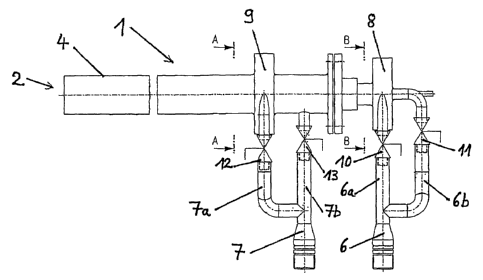
Figure 1 an inventive burner
Figure 2 a section along line A-A
Figure 3 a section along line B-B
In particular, the figures show a burner 1 having a burner head 2, tube 4 for
an oxygen-
containing gas and a combustion gas tube 3 (not shown). The two tubes are
arranged
concentrically in such a way that the combustion gas tube 3 is mounted inside
the tube 4. A
burner 1 having this design is also known as a parallel flow burner. Natural
gas is used as the
combustion gas, for example.
Exemplary operation of the burner 1, in which the two gas flows are co-
rotationally swirled, is as
follows: when the valve 10 is opened, natural gas flows from the gas inlet
line 6 through the line
6a into the swirl chamber 8, where a swirl'flow is impressed upon the natural
gas flow. In so
doing, the valve 11 is closed.
Oxygen-enriched air is sent through the gas line 7 and the line 7a into the
swirl chamber 9, where
a co-rotational swirl flow in the same direction as the natural gas flow is
impressed upon this gas
flow. In so doing, the valve 12 is opened and the valve 13 is closed.
The flow of oxygen-enriched air leaves the swirl chamber and is introduced
into the tube 4. The
natural gas flow is introduced into the combustion gas tube 3.


CA 02554034 2006-07-19
WO 2005/071314 6 PCT/EP2005/000332
The two gas flows become mixed at the burner head 2, resulting in a
characteristic flame. The
shape of the resulting flame depends directly on the setting of the valves 10,
11, 12 and 13.
For example, the flame becomes longer when the combustion gas flow is added
with the valve
11 opened and the valve 10 closed, i.e., no swirl flow is impressed upon the
natural gas flow.
The flame becomes longer in comparison with the just described flame, in which
a swirl flow is
impressed upon both gas flows.
Likewise, it is possible for only the natural gas flow to have the swirl flow
and for the flow of
oxygen-containing gas to be supplied without the swirl flow through the line
7b and the opened
valve 13 to the tube 4.
Due to the design of the valves 10, 11, 12 and/or 13 as regulating valves,
intermediate settings,
i.e., adjustable degrees of opening of these valves are made possible.
Therefore, the shape of the
flame is continuously adjustable. The shape of the flame is varied-without
problem during
operation of the burner 1-by means of the control unit or regulating unit for
the valves 10, 11,
12, 13.
The quantities of combustion gas and oxygen-containing gas supplied must be
taken as boundary
conditions for the shape of the flame. Once the supplied amounts have been
selected, they
remain constant during operation of the burner. A short bushy and broad flame
to a long narrow
flame is simply produced through the choice of the valve settings for the
valves 10, 11, 12, 13.

Representative Drawing
A single figure which represents the drawing illustrating the invention.
Administrative Status

For a clearer understanding of the status of the application/patent presented on this page, the site Disclaimer , as well as the definitions for Patent , Administrative Status , Maintenance Fee  and Payment History  should be consulted.

Administrative Status

Title Date
Forecasted Issue Date Unavailable
(86) PCT Filing Date 2005-01-14
(87) PCT Publication Date 2005-08-04
(85) National Entry 2006-07-19
Dead Application 2009-01-14

Abandonment History

Abandonment Date Reason Reinstatement Date
2008-01-14 FAILURE TO PAY APPLICATION MAINTENANCE FEE

Payment History

Fee Type Anniversary Year Due Date Amount Paid Paid Date
Registration of a document - section 124 $100.00 2006-07-19
Application Fee $400.00 2006-07-19
Maintenance Fee - Application - New Act 2 2007-01-15 $100.00 2006-12-15
Owners on Record

Note: Records showing the ownership history in alphabetical order.

Current Owners on Record
LINDE AKTIENGESELLSCHAFT
Past Owners on Record
HAECKH, VOLKER
KULKIES, ANDREAS
Past Owners that do not appear in the "Owners on Record" listing will appear in other documentation within the application.
Documents

To view selected files, please enter reCAPTCHA code :


To view images, click a link in the Document Description column. To download the documents, select one or more checkboxes in the first column and then click the "Download Selected in PDF format (Zip Archive)" or the "Download Selected as Single PDF" button.

List of published and non-published patent-specific documents on the CPD .

If you have any difficulty accessing content, you can call the Client Service Centre at 1-866-997-1936 or send them an e-mail at CIPO Client Service Centre.


Document
Description 
Date
(yyyy-mm-dd) 
Number of pages   Size of Image (KB) 
Abstract 2006-07-19 1 30
Claims 2006-07-19 3 111
Drawings 2006-07-19 1 21
Description 2006-07-19 6 259
Representative Drawing 2006-09-19 1 10
Cover Page 2006-09-20 1 53
PCT 2006-07-19 5 250
Assignment 2006-07-19 4 97
Correspondence 2006-09-13 1 27
Assignment 2007-03-23 2 68