Language selection

Search

Patent 2554130 Summary

Third-party information liability

Some of the information on this Web page has been provided by external sources. The Government of Canada is not responsible for the accuracy, reliability or currency of the information supplied by external sources. Users wishing to rely upon this information should consult directly with the source of the information. Content provided by external sources is not subject to official languages, privacy and accessibility requirements.

Claims and Abstract availability

Any discrepancies in the text and image of the Claims and Abstract are due to differing posting times. Text of the Claims and Abstract are posted:

  • At the time the application is open to public inspection;
  • At the time of issue of the patent (grant).
(12) Patent Application: (11) CA 2554130
(54) English Title: DRILL BIT HOLDER/BIT CHANGE-OVER DEVICE
(54) French Title: DISPOSITIF DE SUPPORT DE TREPAN/DE CHANGEMENT DE TREPAN
Status: Dead
Bibliographic Data
(51) International Patent Classification (IPC):
  • B25H 3/00 (2006.01)
(72) Inventors :
  • ZWERGIUS, MORTEN (Denmark)
(73) Owners :
  • ZWERGIUS, MORTEN (Denmark)
(71) Applicants :
  • ZWERGIUS, MORTEN (Denmark)
(74) Agent: ROBIC
(74) Associate agent:
(45) Issued:
(86) PCT Filing Date: 2005-01-24
(87) Open to Public Inspection: 2005-08-11
Examination requested: 2006-11-08
Availability of licence: N/A
(25) Language of filing: English

Patent Cooperation Treaty (PCT): Yes
(86) PCT Filing Number: PCT/DK2005/000047
(87) International Publication Number: WO2005/072915
(85) National Entry: 2006-07-20

(30) Application Priority Data:
Application No. Country/Territory Date
PA 2004 00132 Denmark 2004-01-30

Abstracts

English Abstract


A holder (1) for bits (2) which can retain and store a number of screw bits
(2). The holder (1) is executed in an elastic material such as the elastomer
PUR, for example. A number of holes of a suitable dimension (approx. 6 mm) are
made in the holder (1), facilitating the bits (2) to be pressed into the holes
for retention. The bits (2) are placed with the visible tip (4) inwards and
with the socket (3) outwards, thereby making it possible to get hold of the
socket (3) with the magnetic bit holder (6). The bits (2) can be pressed
tightly into the holes by means of the rotating action of the powered
screwdriver (5), which reduces friction. When the rotation stops, the bits (2)
are retained in the holder (1), and the magnetic bit holder (6) can be freed
of the bit (2). Likewise, the bits (2) should be freed from the holder (1)
again by means of the rotating action of the powered screwdriver 5 together
with a light pull of the magnetic bit holder (6). The holder (1) must be
suitable for keeping in a pocket, alternatively for fastening on clothing, a
belt, the powered screwdriver etc.


French Abstract

La présente invention a trait à un support (1) pour trépans (2) apte au maintien et au rangement de trépans à vis (2). Le support (2) est réalisé en un matériau élastique tel que l'élastomère de résine de polyuréthanne, par exemple. Une pluralité de trous de dimension appropriée (environ 6 mm) sont réalisés dans le support (1) facilitant la compression des trépans (2) dans les trous pour leur maintien. Les trépans (2) sont placés avec la plaquette visible (4) vers l'intérieur et avec la douille (3) vers l'extérieur, permettant ainsi la saisie de la douille (3) avec le support de trépan magnétique (6). Les trépans (2) peuvent être comprimés en un ajustement serré dans le trous par le mouvement de rotation d'un tournevis motorisé (5) qui réduit le frottement. Lors de l'arrêt de la rotation, les trépans (2) sont retenus dans le support (1), et le support de trépans magnétique (6) peut être dégagé du trépan (2). De la même manière, les trépans (2) doivent être dégagés du support (1) à nouveau par le mouvement de rotation du tournevis motorisé (5) conjointement avec une traction légère du support de trépans magnétique (6). Le support (1) doit être apte à être rangé dans une poche, ou pour être fixé sur un vêtement, une ceinture, le tournevis motorisé et autres.

Claims

Note: Claims are shown in the official language in which they were submitted.


-3-
CLAIM.
1. The holder (1) is characterized by being executed in an elastic material in
which holes
of suitable dimensions are made, thereby facilitating the retention of a
number of
screw bits (2) in a satisfactory manner.
The bits (2) are positioned with the visible tip (4) inwards and with the
socket (3) outwards,
making it possible to change bits (2) directly with the magnetic bit holder
(6) by moving the
magnetic bit holder (6) from one bit (2) to another.
2. According to claim 1, the holder for the bits is characterized by being
executed in an
elastic material making it possible to press the bits (2) tightly into the
hole by using the
rotation action from the powered screwdriver (5). The bits (2) must be
retained so that the
magnetic bit holder can be freed (6).
3. According to claim 1, the holder for the bits is characterized by being
executed in an
elastic material which enables the bit (2) to be pulled free from the holder
(1) by the
magnetic bit holder (6), by using the rotating action of the powered
screwdriver (5).
4. According to claim 1,2 and 3, the holder for the bits is characterized by
its suitability for
being kept in a pocket, fastened to clothing, an arm, a belt, a powered
screwdriver etc.

Description

Note: Descriptions are shown in the official language in which they were submitted.


CA 02554130 2006-07-20
WO 2005/072915 PCT/DK2005/000047
Drill bit holder/ bit change-over device.
The invention describes a holder 1, fig. 1 for storing and retaining a number
of drill bits 2,
which are used for screwing in and unscrewing screws.
The bits 2 are used together with a magnetic bit holder 6, fig. 3, which is
mounted on a
powered screwdriver 5, fig. 4.
The bits are inserted into the magnetic bit holder 6, and screws can now be
driven into or
dismounted from a material such as wood, for example.
Holders available on the market today consist mostly of a kind of box or
container which
must be retrieved and opened, and then the bit must be changed manually from
the box to the magnetic bit holder or vice versa when changing to a screw with
a different
slot.
Two hands are needed to carry out the change-over. The change-over is
relatively
awkward and time-consuming; the bits are small and can be difficult to keep
hold of.
Often, the bits will end in a pocket together with other bits, and this
presents the
problem of finding the correct one at the next bit change-over.
The invention will be explained in detail below referring to the drawing, on
which
fig. 1, full-size and in profile, shows a holder for screw bits according to
the invention,
fig. 2, at a reduced scale, shows a holder for screw bits according to the
invention,
fig. 3 shows a magnetic bit holder, and
fig. 4 shows a powered screwdriver.
The special feature achieved by this invention is keeping the bits 2 in one
place, as well
as being able to change a bit 2 without holding it manually. You can keep the
powered
screwdriver in your working hand and take the holder 1 with the other hand.
The holder 1 could also be attached to clothing, a belt, an arm and so on. It
could be
fastened using a clip, a buckle, velcro or similar. It will be possible to
effect the
change-over using only one hand, namely the hand holding the powered
screwdriver 4.
This may be essential if you need the other hand to hold on when working on a
ladder, for
example.
The change-over will be fast and it will be easy to find the correct bit 2, as
the tip 4 of
the bit 2 is visible.
The holder 1 is executed in an elastic material which regains its shape and is
durable. The
holder 1 could be executed in an elastomeric material such as PUR.


CA 02554130 2006-07-20
WO 2005/072915 PCT/DK2005/000047
-2
The holder 1 has been provided with holes of a dimension which will retain the
bits 2
(approximately 6 m/m). The bits 2 are positioned with the sockets 3 outwards,
thereby
facilitating getting hold of the socket 3 with the magnetic bit holder 6, and
with the tip 4
visibly inwards.
The holder may assume alternative shapes depending on whether it will be kept
in a
pocket, on a belt, or whether it will be attached to clothing or maybe to the
powered
screwdriver 6 etc.
The bits 2 are retained in the holder 1 because the hole is smatter than the
dimension of
the individual bit 2, whereby the elastic material will squeeze around the bit
2 and retain it
90 in the holder 1. To deposit the bit 2 in the holder 9, the tip 4 is
inserted into the hole of the
holder 1 and by letting the powered screwdriver 5 rotate slightly, the bit can
be pressed
into the hole. When the bit 2 rotates, the friction befween the bit 2 and the
elastic material
will decrease, and one can easily press the bit 2 into place in the holder 1
where it will
remain firmly in place when the rotating stops, sufficiently to enable the
magnetic bit
holder 6 to be freed from the bit 2 which wilt then be deposited into the
holder 1.
To free the bit 2 from the holder 1, the magnetic bit holder 6 is once more
placed over the
bit 2 and the powered screwdriver 5 is allowed to rotate slightly. When the
bit 2 rotates, the elastic material will (with a slight pull) and due to the
bit's shape
automatically push the bit 2 free of the holder, and the bit 2 wilt be
repositioned in the
magnetic bit holder 6.
The holder may be executed in an etastomeric material such as PUR. The
illustrated
holder 1, fig. 1 is executed by cutting both shape and holes from a 15 mm
sheet of
PUR. In the event of production, the holder can be extruded in the same
material.
The holder is developed to function with bits 2 and magnetic bit holders 6
presently
available on the market.
The holder may assume severs! alternative shapes and be provided with a clip,
buckle or
other device whereby it can be attached to clothing, a belt and so on.
Text items such as bit dimension could be embossed on to the holder in the
extruding
process.
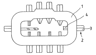
Representative Drawing
A single figure which represents the drawing illustrating the invention.
Administrative Status

For a clearer understanding of the status of the application/patent presented on this page, the site Disclaimer , as well as the definitions for Patent , Administrative Status , Maintenance Fee  and Payment History  should be consulted.

Administrative Status

Title Date
Forecasted Issue Date Unavailable
(86) PCT Filing Date 2005-01-24
(87) PCT Publication Date 2005-08-11
(85) National Entry 2006-07-20
Examination Requested 2006-11-08
Dead Application 2009-08-06

Abandonment History

Abandonment Date Reason Reinstatement Date
2008-08-06 R30(2) - Failure to Respond
2008-08-06 R29 - Failure to Respond
2009-01-26 FAILURE TO PAY APPLICATION MAINTENANCE FEE

Payment History

Fee Type Anniversary Year Due Date Amount Paid Paid Date
Application Fee $400.00 2006-07-20
Request for Examination $800.00 2006-11-08
Maintenance Fee - Application - New Act 2 2007-01-24 $100.00 2006-11-10
Maintenance Fee - Application - New Act 3 2008-01-24 $50.00 2007-12-05
Owners on Record

Note: Records showing the ownership history in alphabetical order.

Current Owners on Record
ZWERGIUS, MORTEN
Past Owners on Record
None
Past Owners that do not appear in the "Owners on Record" listing will appear in other documentation within the application.
Documents

To view selected files, please enter reCAPTCHA code :


To view images, click a link in the Document Description column. To download the documents, select one or more checkboxes in the first column and then click the "Download Selected in PDF format (Zip Archive)" or the "Download Selected as Single PDF" button.

List of published and non-published patent-specific documents on the CPD .

If you have any difficulty accessing content, you can call the Client Service Centre at 1-866-997-1936 or send them an e-mail at CIPO Client Service Centre.


Document
Description 
Date
(yyyy-mm-dd) 
Number of pages   Size of Image (KB) 
Drawings 2006-07-20 1 13
Claims 2006-07-20 1 31
Abstract 2006-07-20 1 61
Description 2006-07-20 2 111
Representative Drawing 2006-07-20 1 5
Cover Page 2006-09-20 1 42
PCT 2006-07-20 3 96
Assignment 2006-07-20 5 125
Prosecution-Amendment 2006-11-08 1 40
Fees 2006-11-10 1 40
Correspondence 2007-11-05 2 66
Fees 2007-12-05 1 48
Prosecution-Amendment 2008-02-06 3 81
PCT 2006-07-21 4 168