Note: Descriptions are shown in the official language in which they were submitted.
CA 02554224 2006-07-21
WO 2005/077280 PCT/GB2005/000437
1
An Endoluminal Surgical Delivery System
The present invention relates to a system and method for delivering to the
locus of an
artery small surgical implants (such as staples) that are positioned intra-
murally or
trans-murally. Other applications of the system include the delivery of a
temporary or
permanent implant within a vessel but at a controlled and significant distance
from the
central axis of that vessel.
Examples of vascular devices that can be delivered by the system are fixation
staples
or clips, occlusion coils, anastamosis devices and stents which are to be at
least
partially passed through the walls of a previously implanted graft. The
delivery
system enables staples, clips or other fixation devices to be passed from
within the
lumen of a vessel, through the wall of a graft or stent-graft and at least
partially
through the wall of the vessel, thereby attaching the graft or stent-graft to
the vessel
wall.
Endoluminal surgery is a rapidly expanding field and permits implants to be
delivered
and minor surgical procedures to be carried out within the lumen of vessels,
most
commonly in arteries. The main instruments used in the technique to traverse
the
arterial tree, from a puncture site in the skin to the destination site of the
procedure,
are guide wires, which pass through the vessel, and catheters, which are
passed over
the guide wires. By appropriate choice of combinations of guide wire and
catheter,
the system can be advanced through the vascular tree to the desired delivery
site.
Frequently, a stent or stent-graft (which are essentially open cylindrical
structures) are
passed through the catheter from outside the patient to the delivery site and,
when
released, these stents or stent-grafts expand to lie coaxially with the native
vessel,
their walls lying in close contact with the walls of the vessel.
Currently, it is very difficult to direct a guide wire or catheter into the
wall of a vessel
at a specific site because wires and catheters tend to lie approximately
parallel to the
CA 02554224 2006-07-21
WO 2005/077280 PCT/GB2005/000437
2
axis of a vessel. Surgery will be eased by the ability to follow a guide wire
along the
axis of a vessel to a certain point and then to be able to move laterally away
from the
guide wire to deliver an implant in a position which is displaced from the
wire,
possibly in the wall of the vessel and not parallel to (and preferably at an
angle
approaching 90 to) the principal axis of the vessel.
US 5,957,863 (Boston Scientific) and US 6,283,960 (Oratec Interventions, Inc.)
both
disclose delivery systems in which a deflectable shaft/catheter is employed
which may
be deflected towards a vessel wall by pulling on a deflection wire attached to
one side
of the tip of the shaft/catheter. However, the relatively small radius of
cross-section
of the shaft/catheter tip results in a very small moment of deflection.
In accordance with a first aspect of the present invention, there is provided
a system
for delivering a staple to a locus of an artery, comprising a delivery conduit
for
inserting into the lumen of an artery through which conduit a staple can be
delivered
to the locus, and means for translating axial advancement of the delivery
conduit
through the artery into movement of the distal end of the delivery conduit
away from
the longitudinal axis of the artery and towards the artery wall.
The means for translating preferably comprises an elongate element for
inserting into
said artery and means for coupling the elongate element and the delivery
conduit in
situ, the elongate element being stiffer than at least the distal end of the
delivery
conduit
The system may involve two guiding means, primary and secondary (corresponding
to the elongate element and delivery conduit respectively). The primary
guiding
means may be a conventional guide wire and is introduced from outside the
patient,
through the patient's vessels to at least as far as the intended delivery site
of the small
implant. The secondary guiding means is able to follow the primary guiding
means
for at least part of the length of the primary guiding means. Said secondary
guiding
CA 02554224 2006-07-21
WO 2005/077280 PCT/GB2005/000437
3
means is controlled by the practitioner so that at a point along the primary
guiding
means, the secondary guiding means can be wholly or partially separated from
the
primary guiding means and steered in a direction which is different from that
of the
primary guiding means.
Preferably, either one of the primary or the secondary guiding means is
provided with
a locking means which can be used to lock at least the secondary guiding means
in
place within the vessel to prevent both axial and lateral movement in that
vessel. In
the preferred embodiment, the locking means also prevents rotation of the
secondary
guiding means around the principal axis of the vessel.
The preferred embodiment of the secondary guiding means involves sets of
components with two distinct functions. The first set of components controls
the
angle that the secondary guiding means makes with the wall of the vessel and
preferably this is achieved by controlling the angle made by the secondary
guiding
means to the primary guiding means. Preferably, the angle which can be made
between the secondary guiding means and the wall of the vessel can be
controlled by
the practitioner to be up to 90 and for the greatest range of uses, the angle
made
between the secondary and primary guiding means should be capable of being
larger
than 90 , i.e. the tip of the secondary guiding means can be angled to point
backwards
with respect to the tip of the primary guiding means. Useful functions can be
achieved with less sophisticated embodiments if the angle is at least 45 ,
although
some anatomies and some functions will not be accommodated with this
restricted
angle.
It is preferable that the angle made by the secondary guiding means to the
wall of the
vessel can be controlled and varied by the practitioner; however, simpler
systems will
operate with a fixed angle when the implant or surgical procedure can tolerate
this
limitation.
CA 02554224 2012-03-27
4
The second set of components of the secondary guiding means controls the
distance of
the tip of the secondary guiding means from the wall of the vessel and
preferably this
is achieved by controlling the distance of the tip of the secondary guiding
means from
the primary guiding means. For some applications, such as the delivery of
staples,
clips or pins through the wall of a graft or vessel, the tip of the secondary
guiding
means must be in contact with the vessel wall. In some cases, the tip must be
able to
apply significant pressure against the graft or vessel wall so that deployment
of the
staple, clip or pin does not push the wall away from the tip of the secondary
guiding
device. Thus the distance of the tip of the secondary guiding device from the
vessel
wall and the force which it applies to the vessel wall are to be controllable
by the
practitioner.
Such a system as described in general terms above is particularly difficult to
design
for larger vessels, such as the aorta, because the diameter of the vessel is
such that a
stiff guiding means is needed to traverse the width of the vessel and to
provide
support to deliver a trans-mural implant. However, stiffness of the guiding
means
must be sufficiently low to permit tracking through the vascular tree to the
delivery
site and it is difficult to achieve an appropriate degree of stiffness to meet
these
opposing requirements.
A particular use of such a delivery system is to allow an appropriately
designed
fixator pin or staple to be introduced through vessels along a guide wire and
then,
when the delivery site is reached, to divert the fixator or staple away from
the guide
wire and drive it through a graft to attach it to the wall of a vessel. This
is of
particular benefit in attaching stent-grafts to the walls of vessels in order
to prevent or
stop migration of the stent-graft. -
Suitable staples are disclosed in WO 00/07506 and WO 01/58363 (both in the
name
of the present applicant).
CA 02554224 2006-07-21
WO 2005/077280 PCT/GB2005/000437
A simple method of constructing a delivery system with the properties
described
above is to combine at least one balloon, which is mounted on a catheter, with
a
separate delivery conduit. The balloon's catheter and the delivery conduit may
be
5 attached to each other for at least part of their length and in one
embodiment, these
two components can be constructed from a single tubular component with two
lumens. In this case, the two lumens are preferably linked by a thin, flexible
plastic
web which can easily be divided.
In an alternative embodiment of the invention, the balloon's catheter and the
delivery
tube are separate parts which are joined at a single point close to the tip of
the delivery
tube. The attachment means used to make the said join allows the axis of the
end of
the delivery tube to make a changeable angle with respect to the axis of the
catheter,
while preventing the delivery tube from sliding up and down with respect to
the
catheter.
Typically, the balloon's catheter is manufactured from an extruded plastic
material
with an internal diameter sufficient to permit standard guide wires to pass
through. In
aortic surgery, the diameter of guide wires most commonly used is 0.035" and
occasionally 0.038" although in other surgical sites, wires as small as 0.014"
are used.
By designing the balloon's catheter to be able to run over a previously
introduced
guide wire, the balloon's catheter comprises the primary guiding means
described
above. Preferably, the balloon's catheter is extruded with at least two lumens
where
the first lumen is used to pass over the guide wire and the second lumen
transmits
fluid used to inflate the balloon.
In some applications, it is preferable to include a metallic or similar stiff
braid into the
structure of the walls of the balloon's catheter in order to improve the
transmission of
torque from the practitioner, through the catheter, to the tip of the device.
Typical
external diameters of the balloon's catheter for use in the aorta will lie in
the range
CA 02554224 2006-07-21
WO 2005/077280 PCT/GB2005/000437
6
1.5mm to 3.0mm, although this size range will be scaled down for smaller
vessels and
smaller guide wires.
The construction of endovascular balloons is well known in the art. The
balloon used
in the preferred embodiment should be relatively compliant and operated at low
pressures. Compliant balloons are typically manufactured from rubber, such as
latex
rubber or from elastic polymers such as polyurethane. Such balloons are
typically
inflated to pressures of approximately 2 atmospheres, although 5 atmospheres
is used
in some, less compliant balloons. High pressure balloons such as those
manufactured
from polyester or Mylar film are usually operated at pressures of several tens
of
atmospheres in order to dilate stenoses. Such balloons and pressures can be
used in
this device but are less effective unless the size of the balloon matches
closely the size
of the vessel in which it is placed.
Preferably, the balloon is designed so that it does not entirely occlude the
vessel but
provides some passage for blood to flow through or past it. This can be
achieved by
using more than one balloon, typically three balloons, located at the same
axial point
on the balloon's catheter and distributed around the catheter. When inflated
the three
balloons swell to form a `clover leaf shape which allows blood to flow through
the
spaces between the lobes and past the balloon.
Alternatively, single balloons can be constructed with fenestrations. In the
simplest
case, an annular balloon (resembling a doughnut) is inflated with the
balloon's
catheter filling the balloon by an attachment point on the surface of the
inner ring of
the doughnut. In this case, the catheter is slightly offset from the mid-line
of the
balloon. When inflated, the central fenestration of the balloon will provide a
convenient channel for the through-flow of blood. If the balloon is designed
not to be
axi-symmetric, the balloon's catheter can be arranged to lie on the axis of
the vessel
but the balloons' fenestrations must then be offset.
CA 02554224 2006-07-21
WO 2005/077280 PCT/GB2005/000437
7
Alternative locking mechanisms to balloons can be constructed from strips of
suitably
springy material such as wire or strip metal which are arranged to `balloon'
out. Such
an arrangement is constructed by distributing at least two approximately equal
length
wires or strips uniformly around a central shaft and attaching the ends of the
strips to
collars or similar structures which can slide over the shaft. When the collars
are
pushed or pulled together by appropriate means, the wires or strips will
`balloon' out
from the shaft to lock across the width of the vessel. A suitable system is
disclosed in
WO 00/07506.
Other versions of the concept are also possible in which stiffer strips or
wires are
employed with hinges placed at points encountering large strains when the
locking
device is expanded, such as at the collars and in the mid part of the strips
or wires. An
attractive manufacturing technique for such a construct is to use injection
moulding to
form the strips from plastic, the hinges being constructed from sections of
the same
plastic where the thickness has been greatly reduced (so called `living
hinges').
Typically the delivery tube also comprises an extruded plastic conduit.
Preferably at
least the inner surface of the tube is treated to have a low sliding friction,
either by
means of a lubricant, such as a silicon-based grease or oil, or by extruding
or coating
at least the luminal part of the tube from a hard or low friction plastic such
as PTFE.
In some applications, it is preferable to include a metallic or other similar
braid into
the structure of the walls of the delivery tube in order to improve the
transmission of
torque from the practitioner, through the tube, to the tip of the device.
In some embodiments of the device, the properties of the delivery tube will
preferably
vary along the length of the tube. At the tip of the tube, the last few
centimetres can
benefit if made to be less flexible than the rest of the tube and preferably a
pre-set
bend is formed in this stiffer region so as to direct the tube away from the
balloon's
CA 02554224 2006-07-21
WO 2005/077280 PCT/GB2005/000437
8
catheter. In this way, the tube comprises the first part of the secondary
guiding
means.
Other variations can be devised for instance to allow the tube to penetrate
some
distance down small, side-branch vessels. In this case, it may be advantageous
for the
last few centimetres of the tip of the tube to be flexible so that it can
track down the
side branch. A stiffer, pre-curved section would then be position just behind
this
deformable tip so as to direct the tip away from the balloon's catheter.
In a further variation of the tube, at least one stay or tensioning element
manufactured
from a filamentous material such as a braided or monofilament surgical suture
or wire
is attached close to the tip of the tube and is preferably fed through at
least one
additional lumen for at least part of the length of the tube. When tension is
applied to
at least one of the stays or tensioning elements in such a way that more
tension is
applied to one side of the tube than another, then the tube will bend in the
direction of
the greatest tension.
In the simplest embodiment of this variation, a single stay is connected close
to the tip
of the tube and runs back from the tip for a distance of between 2cm and 10cm,
at
which distance it passes through a small hole in the wall of the tube and
continues to
run back for the whole of the rest of the length of the tube inside the tube,
preferably
within its own lumen. Where the tube exits the patient's body, the stay is
attached to
some independent gripping means. When the practitioner pulls on the
independent
gripping means and applies tension to the stay, while at the same time holding
the
tube to prevent the stay from pulling it out of the patient, the tip of the
tube will bend
in response to the tension in the stay.
The attachment means between the tube and the catheter's balloon can be
constructed
with a variety of methods. The simplest is to employ a small lashing with a
thread-
like material such as monofilament or multifilament surgical suture or yarn.
CA 02554224 2006-07-21
WO 2005/077280 PCT/GB2005/000437
9
Preferably, the suture or yarn is passed around the tube and the balloon's
catheter in a
`figure of eight' form so as to provide a point of rotation between the two
and to limit
the relative axial movement between the tube and the catheter. Similar
structures can
be constructed from moulded loops of preferably elastomeric or plastic
material or
from moulded `figures of eight' from similar materials. In order to prevent
axial
relative motion between the tube and the catheter, indents or protrusions can
be
incorporated into the surface of the catheter or the tube or both conduits.
Alternatively, where the tube and catheter are formed from a single extrusion,
a
section of the tube part can be separated from its adjoining section of the
catheter part
as a manufacturing step. A short section, typically between 1 and 5mm long,
where
the attachment between the tube and catheter has not been separated, located
towards
the tip of the tube will also provide a suitable degree of flexion between the
tube and
catheter. In some embodiments, it will be possible to retain attachments of
both
lumens for the majority of their lengths, separation only being required at a
point
where the balloon can be inserted between the tube and catheter.
Preferably, where there is a single balloon, fenestrated balloon or group of
lobular
balloons, the tube is arranged to run past the outside of the balloon and to
curve away
from the balloon's catheter once it has passed the balloon. In another
embodiment of
the device, a second balloon, fenestrated balloon or group of lobular balloons
is
arranged at a second point along the length of the balloons catheter.
Preferably, the
tube is arranged to run past the first balloon or group of balloons and to
bend away
from the balloon's catheter before reaching the second balloon or group of
balloons
which are located further along the balloon's catheter.
In all arrangements here described, the first function of the first balloon or
group of
balloons is to fix the balloon's catheter in the vessel to prevent it from
moving axially,
laterally or from rotating.
CA 02554224 2006-07-21
WO 2005/077280 PCT/GB2005/000437
A second function of the first balloon is to permit the tube to form its curve
away
from the balloon's catheter using the full diameter of the vessel. This allows
the
radius of the bend of the tip of the tube to be greater which permits it to be
manufactured from stiffer material and which permits longer or stiffer
implants or
5 devices to be passed therethrough. Were the tube to bend away directly from
the
balloon's catheter towards the wall of the vessel without first reaching the
opposite
wall of the vessel, the bend of the tube would have to be completed within
just the
radius of the vessel requiring the tip of the tube to be more flexible and
restricting the
stiffness or length of implants or devices past through the tube.
A third function of the first balloon is to deflect the tube so that it bends
away from
the balloon's catheter and is pushed against the wall of the vessel, locking
it in place.
In use, the position at which the sheath is pressed by the balloon against the
vessel
wall is approximately opposite the part of the wall where the tip of the
secondary
guidance means is intended to contact.
A fourth function of the first balloon is to support the tube at approximately
the
midpoint of its traverse from one wall to the opposite wall of the vessel.
Where this is
a significant distance, such as in the aorta, the tube can lack the stiffness
required to
deliver a staple or fixation device successfully. Attachment of the tube at
this said
approximate midpoint approximately halves the unsupported length of the tube
and
greatly increases the stability of this part of the delivery system.
Where two balloons or groups of balloons are employed, the function of the
second
balloons or group of balloons is both to provide supplementary fixation and
also to
occlude or reduce the flow of blood. This is because in some applications,
such as
stapling at the neck of an aortic aneurysm, the first balloon may be situated
within
part of a stent-graft that is not well fixed to the walls of the vessel. In
this case,
inflation of a single balloon and the subsequent force of blood upon it may
cause the
balloon to dislodge the stent-graft, causing it to migrate before a fixation
device has
CA 02554224 2006-07-21
WO 2005/077280 PCT/GB2005/000437
11
been deployed. In this type of case, the second balloon can be inflated
upstream of
the first balloon in a region of the vessel where there is no stent-graft or
where the
second balloon will be firmly fixed against the wall of the vessel. Once
inflated, the
second balloon will reduce or occlude the pressure of blood striking the first
balloon,
reducing or removing the risk of it migrating and causing an unwanted
migration of a
stent-graft or other such structure.
Preferably the first balloon or group of balloons can be inflated
independently of the
second balloon or group of balloons, for example by the use of separate
inflation
lumens in the balloon's catheter.
Typically the delivery tube will have an internal diameter between 1mm and 7mm
depending upon the application.
Some benefits may accrue if more than one inner tube is deployed around the
delivery
tube as this permits the simultaneous or near-simultaneous deployment of more
than
one implant or device at different points around the circumference of the
vessel. Such
a modification to the design at its simplest involves the duplication of the
tube
components.
In accordance with a second aspect of the present invention, there is provided
a
method for delivering a staple to a locus of an artery, comprising carrying
out the
following the steps in any convenient order:
(i) loading a staple into a delivery conduit,
(ii) inserting the conduit into the lumen of an artery, together with means
for
translating axial advancement of the delivery conduit through the artery into
movement of the distal end of the delivery conduit away from the longitudinal
axis of the artery and towards the artery wall,
(iii) positioning the distal end of the conduit near the locus,
CA 02554224 2006-07-21
WO 2005/077280 PCT/GB2005/000437
12
(iv) advancing the conduit through the artery relative to said means for
translating
movement in order to move the distal end of the conduit away from the
longitudinal axis of the artery and towards the artery wall, and
(v) ejecting the staple from the conduit at the locus.
In the simplest embodiment, a delivery catheter is passed through the tube. At
the tip
of the tube, which is arranged either by pre-curvature or by the action of the
balloon
or by both of these characteristics, to point away from the balloon's
catheter, the
delivery catheter can be advanced through the tip of the tube and towards its
eventual
target site. Thus the delivery tube can be pushed into contact with the wall
of the
vessel and can be made to exert a significant force against that wall. In some
embodiments, the tip of the delivery catheter is also curved in order that it
makes a
greater angle with the axis of the balloon catheter.
In some applications, the delivery catheter is conveniently pre-loaded with a
staple or
other fixator. Preferably, the sheath is fitted with a haemostatic valve at
the end
which lies outside the patient and this permits the delivery catheter to be
completely
withdrawn from the delivery system after its staple of fixator contents have
been
deployed. Once removed, the delivery catheter can be replaced with a second
delivery catheter, allowing a subsequent staple or fixator to be deployed
without
having to move the delivery system from the deployment site of the previous
staple or
fixator.
For the application of deploying staples disclosed in WO 01/58363 in the name
of the
present applicant in which the staples are biased to open outwards from an
initial,
approximately linear configuration, the diameter of the lumen of the delivery
catheter
will preferably lie in the range 2mm 1mm. These dimensions are appropriate
for
staples of the said design which have a deployed width lying in the range 10mm
to
15mm. Other sizes of staple will require appropriate scaling of the diameter
of the
delivery catheter.
CA 02554224 2012-03-27
13
Preferably, an overall sheath is used to contain the balloon, balloon's
catheter, the
delivery tube and the delivery catheter. Preferably, the tip of the balloon's
catheter is
furnished with a tapered nose cone that will allow the overall sheath to pass
through
the vessels without damaging the vessel walls. The diameter of the overall
sheath will
lie in the range 8 to 30 French (2.6mm to 10mm) although currently constructed
prototypes lie in the range 14 French to 20 French (4.6mm to 6.6mm). Slightly
smaller systems can be designed with sheath sizes of 5French but these systems
involve the finest guide wires, dual or multiple purpose lumens and advanced
materials. Preferably the overall sheath is constructed from a stiff plastic
such as
nylon or PTFE and itself is fitted with a haemostatic valve to prevent leakage
of blood
where the sheath and balloon's catheter exit from the back of the overall
sheath.
Preferably, at least one of the sheath, the balloon's catheter and the
delivery sheath are
fitted with a suitable handle or gripping region to allow the practitioner to
manipulate
these conduits from outside the patient.
In use the following steps are used to deploy a staple such as that disclosed
in WO
01/58363.
= A guide wire is introduced into the patient so that it lies in the vessel
into
whose wall the staple is to be delivered. The guide wire is preferably
advanced several tens of centimetres beyond the delivery site.
= The delivery site is identified, typically by means of fluouroscopy and
radio-
opaque dye.
= The delivery system is fed onto the guide wire with the wire passing through
the lumen of the balloon's catheter.
CA 02554224 2006-07-21
WO 2005/077280 PCT/GB2005/000437
14
= The delivery system is advanced through the patient until the end of the
sheath
is approximately opposite the intended delivery site of the staple.
= Holding the delivery system still, the overall sheath is pulled back to
release
the balloon and sheath within the vessel.
= The balloon and sheath are manipulated until the sheath is pointing at the
correct part of the wall of the vessel.
= The balloon is inflated.
= The delivery catheter is advanced through the sheath until it is in near
contact
with the wall of the vessel.
= Pressure in the balloon is slightly reduced to permit fine adjustment of the
position of the tip of the delivery catheter.
= When the tip of the delivery catheter is correctly aligned, the balloon is
inflated up to its maximum recommended pressure.
= The delivery catheter is pushed firmly against the wall of the vessel and
the
staple is deployed.
= The delivery catheter is withdrawn, If necessary completely from the
delivery
system.
= A new delivery catheter containing a new staple is pushed into the delivery
system and advanced to the wall of the vessel.
CA 02554224 2006-07-21
WO 2005/077280 PCT/GB2005/000437
= The pressure in the balloon is dropped slightly and the tip of the delivery
catheter is repositioned to the delivery site for the new staple.
= The sequence is repeated.
5
A number of preferred embodiments of the invention will now be described, with
reference to the accompany drawings, in which:
Figure 1 shows a schematic overview of a system for delivering a staple in
10 accordance with the invention;
Figure 2 shows a schematic illustration of an alternative embodiment of the
invention;
Figure 3 is a schematic illustration of the embodiment of Figure 2 in use; and
Figures 4-8 are schematic illustrations of further alternative embodiments of
15 the invention.
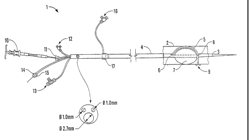
Referring to Figure 1, system 1 comprises sheath 4, which contains delivery
tube 5
and balloon catheter 6 for balloon 7. The entire system is threaded in use
over guide
wire 3 (which resides inside balloon catheter 6) inside vessel 2 (which may be
for
example a human artery).
The distal end of delivery tube 5 is coupled to balloon catheter 6 by lashing
8, which
will be described in more detail below in relation to Figures 4-8.
The tip of delivery tube 5 is flexible and radio-opaque so that it is visible
to radio
imaging equipment to enable the user of system 1 to "see" the end of delivery
tube 5
in situ.
Delivery tube 5 is loaded with staples 9 by staple injector 10 which is
mounted at the
proximate end of system 1 to the user (the opposite end to the locus of vessel
2 to
CA 02554224 2006-07-21
WO 2005/077280 PCT/GB2005/000437
16
which staple 9 is delivered). Staple injector 10 is connected to the proximate
end of
delivery tube 5 via haemostatic valve 11, and slightly downstream of this is
stapler
flushing port 12. Staple injector 10 has a delivery sheath (not shown) which
in use is
threaded through delivery tube 5 to the distal end thereof for delivery of
staples 9.
Proximate end of system 1 also has guide wire port 14, leur port 15, and
balloon
inflation port 13 for balloon catheter 6.
Flushing port 16 is in communication with sheath 4 via haemostatic sheath 17
as
shown on Figure 1. The effective length of the device from haemostatic sheath
17 to
the distal end of balloon catheter 6 is about 750mm. Balloon catheter 6 has an
internal diameter of about 2.7mm and delivery tube 5 an internal diameter of
about
1.0mm, resulting in an approximate total internal diameter of sheath 4 of
about
4.4mm.
In use, guide wire 3 is threaded through the vascular tree of the patient
until it reaches
the locus of the artery where it is intended to deliver a staple. The locus
may for
example be where a graft or stent-graft is in place which it is desired to
attach to the
artery wall. The delivery site is typically identified by means of fluoroscopy
and
radio-opaque dye.
Sheath 4 is then threaded over the part of guide wire 3 external to the
patient's body
(by means of balloon catheter 6) and sheath 4 is then carefully advanced over
guide
wire 3 down through the vascular tree until the distal end is approximately
opposite
the intended delivery site of the staple.
Whilst holding system 1 immobile, sheath 4 is retracted to release balloon
catheter 6
and delivery tube 5 within vessel 2. These are then manipulated till the
distal end of
delivery tube 5 is pointing at the correct part of the wall of vessel 2.
CA 02554224 2006-07-21
WO 2005/077280 PCT/GB2005/000437
17
Balloon inflation port 13 is then opened and filled with air to inflate
balloon 7,
thereby locking balloon catheter 6 in vessel 2 by contact of balloon 7 with
its walls.
Advancement of delivery tube 5 through sheath 4 is resisted by lashing 8 which
connects delivery tube 5 to balloon catheter 6. Further advancement of tube 5
therefore results in deflection of the distal end of tube 5 away from the
longitudinal
axis of vessel 2 and towards its wall at an angle approaching 90 .
Pressure in balloon 7 maybe slightly reduced putting a fine adjustment of the
position
of the tip of tube 5, following which balloon 7 can be fully inflated. Tube 5
is then
pushed firmly against the wall of vessel 2 and staple 9 is deployed.
Once the staple has been deployed, delivery tube 5 can be withdrawn, if
necessary
completely, from system 1 and a new delivery tube containing a new staple can
be
inserted into system 1 and advanced to a new locus.
In an alternative embodiment, inflation of balloon 7 may cause delivery tube 5
to
follow an arc around the perimeter of balloon 7, thereby angling distal end of
delivery
tube 5 approximately perpendicular with the walls of vessel 2.
As mentioned above, in one embodiment the present invention delivery tube 5 is
attached to balloon catheter 6 by means of lashing 8. Referring to Figures 2
and 3,
however, an alternative embodiment comprises balloon catheter 20 and delivery
tube
21 which are formed from the same plastics material and are joined by a thin
web.
Web may then be removed along with the majority of the lumens (23) leaving
join 22.
In use, advancement of delivery tube 21 along the axis of an artery whilst
balloon
catheter 20 remains relatively immobile causes delivery tube 21 to bend
towards the
artery wall as shown schematically in Figure 3.
CA 02554224 2006-07-21
WO 2005/077280 PCT/GB2005/000437
18
Four alternative embodiments involve different ways of lashing a delivery tube
to an
elongate element (such as a balloon catheter) are shown in Figure 4-8.
Figure 4 shows delivery tube 31 attached to catheter 30 by means of a suture
32 which
is looped around catheter 30 and attached to tube 31 by means of crimp band 33
and
heat-shrink sleeve 34.
In Figure 5, catheter 30 and delivery tube 31 are coupled by means of suture
32 which
has been formed into a figure-of-eight and knotted.
Figure 6 shows an arrangement in which suture 42 is looped around delivery
tube 41
and then threaded through fenestrations 44 in catheter 40 where it is bonded
in place
(for example with adhesive).
Figure 7 shows an alternative arrangement also involving fenestrations 44 in
catheter
40 in which a twist 43 is placed in suture 2 and delivery tube 41 passed
through the
resultant loop. The loop is then attached to tube 41 by means of a heat-shrink
sleeve
46 having a hole 47 therein. Radio-opaque marker band 45 is employed at the
distal
end of tube 41. Figure 8 shows a completed view of the attachment means of
Figure
7.