Note: Descriptions are shown in the official language in which they were submitted.
CA 02554643 2001-04-24
76186-39D
METHODS AND APPARATUS FOR MIXING FLUIDS
This application is a divisional of Canadian patent
application serial No. 2,433,189 filed on April 24, 2001.
Field of The Invention
The field of the invention relates to fluid mixing
and distribution.
Background of The Invention
Many commercial processes involve mixing of fluids,
including especially catalytic reactors and large
fractionation columns. Such mixing is not always a simple
matter, especially where the fluid has multiple phases (such
as liquids and gases/vapors), and where large volumes are
being rapidly mixed. Numerous mixing apparatus are known,
and some of these are described in US 6098065 to Jacobs et
al. (August 2000). Jacobs et al. teach several improvements,
some of which involve bubble caps spaced apart on a
distribution plate.
Bubble caps generally comprise a riser and a cap,
arranged such that a fluid flows upwards in a space between
the cap and the riser, reverses direction and then flows
downward through a passageway in the riser. In the absence
of swirl directors, the fluid flow path is thus generally in
the shape of an inverted "U". Bubble caps are generally
affixed to a distribution plate, and the passageway through
the riser is confluent with a hole in the distribution
plate. Bubble caps often contain a plurality of side slots
that provide an entrance for the gas phase into the annular
space between the riser and the cap. The gas entrains
liquid present in the annular space. See, for example, U.S.
Patent No. 5,158,714 to Shih et al. (October 1992).
There must be some mechanism for maintaining the
position of the riser with respect to the cap. It is known
1
CA 02554643 2001-04-24
76186-39
to use cantilevered arms or other spacers for that purpose.
See, for example, U.S. Patent Nos. 5,989,502 to Nelson et
al. (November 1999) and 4,305,895 to Heath et al.
(December 1981). In the past, such spacers have always been
of minimal size to reduce cost and minimize any flow
effects. Prior art spacers therefore exclusively serve a
positioning function, and do not materially assist in either
fluid flow or mixing.
Skirt height has been shown to materially affect
the fluid flow and mixing. See, for example, "Optimum
Bubble-Cap Tray Design", Bolles, William L., a four part
series in Petroleum Processing, Vol. 11, No. 2, pp. 65-80;
Vol. 11, No. 3, pp. 82-95; Vol. 11, No. 4, pp. 72-79; Vol.
11, No. 5, pp. 109-120. In this series of articles, Bolles
presents a design methodology for bubble caps of the type
commonly used in distillation columns. In such columns, the
vapor flow is upward through the bubble cap tray and the
liquid flow is transverse, across the bubble cap tray. Such
flow is typically described as countercurrent flow. In the
Bolles article, at Vol. 11, No. 3, p. 87, a skirt height of
0.5 inches to 1.5 inches is recommended, and there is a
suggestion that greater skirt heights would be
disadvantageous. There is certainly no teaching,
suggestion, or motivation of which the current applicants
are aware, for skirt heights greater than 1.5 inches.
Conversely, Ballard et al. (U. S. 3,218,249)
teaches the use of bubble caps as a mixing and distribution
means for the concurrent downflow of vapor and liquid.
Ballard et al. teaches skirt heights of any distance "...above
the distribution tray so long as the flow of gas through the
downcomers is not sealed off; a reasonable range being from
a level corresponding to practically no distance above the
2
CA 02554643 2001-04-24
76186-39
tray to a distance of about one foot thereabove." Ballard
et al. further teaches that "...the liquid phase, disengaged
from the vapor phase by gravity, fills up on tray 18 to a
level below the slot depth in the downcomer caps, such level
being determine primarily by the gas flow rate per cap. It
is, of course, necessary that some of the slot openings be
exposed above the liquid surface to permit passage of vapor
therethrough. Where the caps have no slots, the liquid
level on the tray will be below the bottom rims of the caps
for the same reason. Where unslotted caps are used,
clearance between the bottom rim and the tray must be
maintained to accommodate the passage of gas and liquid
thereunder." Clearly, the skirt height dimensional range
taught by Ballard, et al. applies specifically to an
unslotted cap, because vapor flow through a slotted cap can
not be blocked off by reducing the skirt height to
practically no distance. There is no teaching of a specific
dimensional range suitable for slotted bubble caps.
Shih, et al. (U.S. 5,158,714) teaches the use of a
dispersion plate to improve the distribution of liquid
exiting the riser. Gamborg, et al. (U. S. 5,942,162) teaches
the use of a slotted bubble cap, modified such that the cap
is non-concentric with the riser, to improve the uniformity
of liquid distribution. Gamborg, et al. describe this
modified bubble cap as a vapor lift tube, wherein the cap is
called an upflow tube and the riser is called a downflow
tube. Nonetheless, the fluid flow path is the shape of an
inverted "U", flowing first upward through the upflow tube
and then downward through the downflow tube. Jacobs, et al.
(U. S. 6,098,965) teaches the use of riser vanes and/or
target plates to improve the distribution of liquid exiting
the riser. Aside from the patents cited above, the current
applicants are not aware of any other information in the
3
CA 02554643 2001-04-24
76186-39
public domain that discloses technological advances in the
use of bubble caps as a mixing and distribution means for
the concurrent downflow of vapor and liquid.
Some systems that utilize bubble caps provide for
rough distribution of fluids upstream of the bubble caps. A
patent granted to Stangeland, et al. (U. S. 5,690,896
November 1997) describes an apparatus for rough distribution
comprising a perforated plate located directly above the
bubble cap tray. With this approach, the perforations must
pass both the gas phase and liquid phase fluids. As a
result, the prevailing liquid level on this tray may be
quite low, thereby negatively impacting the quality of rough
distribution. A patent granted to Grott, et al. (U. S.
5,837,208 November 1998) describes an apparatus for rough
distribution consisting of a perforated tray surrounded by a
cylindrical wall. With this approach, the gas phase fluid
can flow through the annular area between the perforated
tray and the reactor wall, while the liquid phase fluid
flows primarily through the perforations. One drawback of
this approach is that the annularly downflowing gas phase
fluid can disturb the liquid surface on the bubble cap tray,
thereby negatively impacting the performance of the bubble
cap tray. Finally, with both of the above approaches, the
perforated trays restrict inspection and maintenance access
to the bubble cap tray.
Thus, there is still a need for improved methods
and apparatus for mixing and distributing fluids, including
improvements to bubble cap trays and rough distribution
mechanisms.
4
CA 02554643 2001-04-24
76186-39D
Summary of the Invention
The invention provides a distribution device
comprising: a plurality of flow-redirecting vanes, an upper
plate having at least one fluid inlet orifice; a lower
plate, the plates disposed in relation to the vanes such
that a fluid flows outwardly through a space between the
plates and discharging through a fluid outlet orifice
defined by the plates and the vanes; and a distribution
tray, disposed below the lower plate.
Various objects, features, aspects and advantages
of the present invention will become more apparent from the
following detailed description of preferred embodiments,
along with the accompanying drawing in which like numerals
represent like components.
Brief Description of The Drawing
Figure 1 is a vertical cross-section of a prior
art bubble cap.
4a
CA 02554643 2001-04-24
76186-39D
Figure 2A is a vertical cross-section of a bubble
cap according to aspects of the present invention.
Figure 2B is a horizontal cross-section of the
bubble cap taken along the view line 1-1 of Figure 2A.
Figure 3 is a vertical cross-section of another
bubble cap, having multiple dividers and an increased skirt
height due to a decreased cap length.
Figure 4 is a vertical cross-section of another
bubble cap, having multiple dividers and an increased skirt
height due to an increased riser height.
Figure 5 is a side view of the bubble cap of
Figures 2A and 2B showing slide slots.
Figure 6 is a perspective view of a distribution
plate having multiple bubble caps, showing fluid cross-flow.
Figure 7A is a perspective view of a distribution
apparatus having chevron-type vanes.
Figure 7B is a vertical cross-section of the
distribution apparatus of Figure 7A taken along line 1-1,
and surrounding apparatus.
Figure 7C is a horizontal cross-section of
chevron-type vanes in the distribution apparatus of
Figure 7B taken along line 2-2.
Figure 8 is a horizontal cross-section of wave
plate-type vanes.
Figure 9 is a horizontal cross-section of
staggered channel-type vanes.
5
CA 02554643 2001-04-24
76186-39D
Detailed Description
In Figure 1, a prior art bubble cap 10 generally
comprises a riser 20 and a cap 30 separated by a spacer 40.
The bubble cap 10 is attached to a distribution plate 15.
The spacer 40 is very small with respect to the lengths of
both riser 20 and cap 30, and the skirt height 60 is less
than 1.5 inches. The fluid flow path 70 through the bubble
cap is generally in the shape of an inverted "U"
5a
CA 02554643 2001-04-24
WO (12/l)s1:i30 PCT/USO1/13-t3G
W Figures 2A and 2B, a bubble cap 100 generally comprises a riser 120 and a
cap 130
separated by a plurality of dividers 140. The bubble cap cooperates with a
distribution plate 115
to locally mix the fluids. (_gs used herein, the temp "fluid" means anything
that flows, including
especially a vapor phase or a liquid phase, or a mixture comprising at least
two phases. The term
also includes any fluid that is mixed and distributed in a commercial
process.)
The riser I20 has a top 122 and a riser height 125 defined by a distance
between the top
122 of the riser 120 and the top 116 of the distribution plate 115. The riser
120 also defines an
inner passageway 190. Contemplated risers can be formed of any suitable
material, including
carbon steel, stainless steel and other alloys, plastic, and ceramics,
depending in large measure
upon the ternperatm-e and corrosiveness of the fluids being mixed. Such risers
cm also have
virtually any suitable overall dimensions. The overall shapes are also subject
to variation.
Although tubular risers having circular horizontal cross-sectional areas are
preferred, it is also
contemplated to provide tubular risers with elliptical, square, rectangular,
or other horizontal
cross-sectional areas. Risers need not even have uniform passageways along
their length.
Preferred risers may also have swirl directors 150 above or witlun (not shown)
the passageways.
The cap 130 has a top 132, a bottom edge 134, and a cap length 135 defined by
a distance
between the top 132 of the cap 130 and the bottom edge 134 of the cap 130. The
cap 130 also
has a shirt height 160 defined as the distance between the bottom edge 134 of
the cap 130 and
the top 116 of the distribution plate 115. Contemplated caps can again be
formed of any suitable
material, including carbon steel, stainless steel and other alloys, plastic,
and ceramics, depending
again in large measure upon the temperature and corrosiveness of the materials
being yixed.
Preferred caps have houizontal cross-sectional areas of similar shape to that
of the associated
riser, but may also have other shapes. For example, a cylindrical cross-
section riser may have a
rectang~:lar cross-section cap.
The skirt height 160 is a function of the riser height 125, the cap length
135, and the
distance between the top 122 of the riser 120 and the top 132 of the cap 130.
Preferred bubble
caps have a riser 120 acid cap 130 that cooperate to provide a skirt height of
no less than 1.5".
More preferred bubble caps have a skirt height of at least 1.75 inches, and
even more preferred
bubble caps have a shirt height of at least 2.0 inches, at least 2.5 inches,
at least 3 inches, and at
s
CA 02554643 2001-04-24
W O l)2/05'1 6311 PCT/US111/13.13C
least 4 inches. The unusually high slcirt heights are preferably achieved by
using an especially
long riser rather than using an especially short cap, although all
combinations are contemplated.
Without being limited to any paa.-ticular theory or contemplated mode of
operation, the
present inventors contemplate that a skirt height of no less than 1.5 inches
is advantageous
because it enhances cross-flow of fluids moving on the top 116 of the
distribution plate 115.
Hydraulic calculations show that skirt heights up to 3 inches or higher may
also be advantageous,
depending largely upon the quantity of the liquid phase being conveyed across
the top 116 of the
distribution plate 115, and subsequently through the space 180 between the
riser 120 and the cap
130 and the riser passageway 190. Although not presently considered to be a
preferred
embodiment, it is also contemplated that the bubble caps on a distribution
plate need not all have
the same skirt height. For example, some skirt heights may be less than 2
inches while others are
more than 2 inches. Alternatively, all skirt heights may be more than 2
inches, and some may be
more than 2.5 inches. It may even be advantageous for the bubble caps having
relatively higher
skirt heights to be positioned around the periphery of the distribution plate,
or in some other
manner, depending, at least in part, on where the fluids are introduced to the
distribution plate.
Alternatively, the slots can be lengthened, Preferred slots can be at least
2.5 inches long,
more preferably at least 3.5 inches long, still more preferably at least 4
inches long, at most
preferably at least 5 inches long.
The dividers 140 in Figure 2A and 2B preferably span essentially the entire
distance from
the sidewall of the cap 130 to the sidewall of the riser 120. The dividers are
positioned near the
top 122 of riser 120. Other embodiments, however, are also contemplated. For
example,
dividers are currently contemplated to be Long enough to have a significant
impact on the
hydraulics of the fluid flowing in the space 180 between the riser 120 and the
cap 130. Preferred
dividers 140 impact the fluid hydraulics by having a length of at least 50% of
the riser/cap span,
preferably 70% of that distance, more preferably 90+% of that distance. In an
alternative
embodiment (not shown), the dividers can extend fi-om the top, of the cap al
the way to the
bottom edge 134 of the cap. The dividers need not be continuous, in that they
may be
constnzcted in several shorter dividers, as long as the sum of the length of
the dividers is at least
50% of the riser/cap span. Contemplated dividers (not shown) may also be
positioned non-
vertically such that they impart a swirl to the fluid rising in the space 180
between the riser I20
CA 02554643 2001-04-24
WO 02/1i51s3(i PCT/US(11/I3.13C>
and the cap 130. Still further, any suitable number of dividers are
contemplated to be utilized in
any given bubble cap, including especially from two, three, fow, five, or six
dividers.
Dividers 140 may be attached to the riser, the cap, or both the riser and the
cap.
Attaclunent may be direct or indirect. Some of the dividers may assist in
maintaiung the
positioning of the riser to the cap, and some may not assist very much, or at
all, in that regard.
Preferred methods of attaclunent izZClude welding, such as taclc-welding,
stitch-welding, or any
other welding means. Dividers may comprise any suitable material or materials.
Swirl director
150 is affixed to the top I22 of the riser 120. The swirl director 150 directs
the fluid 170 from a
space 180 between the riser I20 and the cap I30 to the riser passageway 190 in
a circumferential
flow path, which apparently results in a more uniform wetting of the inner
wall of the riser I20,
and a rinb shaped discharge pattern of the fluid 170, as the fluid 170 exits
the riser passageway
190. The swirl director may be continuous with the riser 120, or may be
affixed to the riser 120
by welding or any other suitable method. W operation, fluid 170 enters the
bubble cap 100
through an opening 117 between the top 116 of the distribution plate 115 and
the bottom edge
I 5 134 of tlae cap 130, defined by a skirt height 160. Tf the bubble cap 100
possesses one or more
slots on the side of the cap 130, fluid will also enter the bubble cap 100
tberethrough. The fluid
170 then enters the space 180 between the riser I20, the cap 130, and the two
dividers 140. The
fluid 170 then flows upward through the space 180 and through the swirl
director 150 where the
fluid 170 is mixed. The fluid than enters the riser 120 and flows downward
through the riser
passageway 190. The cap length 135 is shorter than the cap length 35 of Figure
l, allowing the
slci_rt height 160 to be longer than the skirt height 60 of Figure 1. In the
event that two adj acent
bubble caps 100 are at different elevations, due perhaps to a tilted
distribution tray 115, the two
dividers I40 and the skirt height 160 allow more uniform splitting of the
fluid 170 between the
two adjacent risers than do two adjacent bubble caps 10 of Figure 1.
The distribution plate 115 is preferably circular, and measures between about
36 inches
and about 240 inches in diameter, and between about 0.06 inches and 0.50
inches tluck. The size
generally depends upon the size of the reactor in wluch it is utilized.
CZUTently preferred,
distribution plates are made from stainless steel and other alloys, although
any suitable material,
including carbon steel, plastics. and ceramics are also contemplated. A
typical distribution plate
115 supports between about 60 and about 1200 bubble caps, although lesser or
greater numbers
s
CA 02554643 2001-04-24
WO 02/(151S3U PCT/USII1/13-436
of bubble caps are also contemplated. The risers 120 are typically rolled into
the distribution
plate 115, such that the riser passageways 190 coincide with holes 118 in the
distribution plate
115.
As depicted in the Jacobs patent referenced above with respect to other bubble
caps, the
distribution plate 115 may actually comprise a re-distribution plate because
chambered nuxing
and/or rough distribution may be accomplished upstream. Thus, it should be
apparent that
distribution plate 115 may be placed at any appropriate position with respect
to other processes
and apparatus ill any mixing reactor.
In Figure 3, bubble cap 200 is similar to the bubble cap 100 of Figures 2A and
2B,
except that the bubble cap 200 has four dividers 240 instead of the two
dividers 140. Iu Figure
3, the four dividers 240 are orgaluzed into two sets of two dividers, each set
disposed in separate
vertical planes within a space 280. Within each set, the two dividers are
disposed within one
vertical plane within the space 280, and separated within the space 280. As a
result, the fluid
270 may pass through the space 280 formed between the riser 220, the cap 230,
and past the four
dividers 240.
In Figure 4, bubble cap 300 is again similar to the bubble cap 100 of Figures
2A and 2B,
except that the bubble cap 300 has a cap length 335 that is shorter than the
cap length 135, and a
riser height 325 that is shorter than the riser height 125. The result is a
skirt height 360 that is
equal to the sldrt height 160 of the bubble cap 100, even though the riser
heights and cap lengths
are different..
In Figure 5, bubble cap 400 has a cylindrically curved side 433, in which axe
disposed
multiple side slots 495. Each of the multiple side slots 495 extends downward
to the bottom 434
of the cap 430, such that the slot length 497 of any given slot 495 is the
distance from the top .
496 to the bottom 434 of the cap 430. The slot elevation 498 is defined as the
distance between
the top 496 of the slot 495 and the top 416 of the distribution plate 415.
Among other things,
such side slots 495 allow passage into the bubble cap 400 of a fluid 470 being
mixed and
distributed.
CA 02554643 2001-04-24
WO ()2/!);1530 P~'T/US()1/13-l3G
The bubble cap 400 of Fi~.we 5 has at least eight slots 495, fotu~ of which
are shown. The
slot length 497 is 2.5 inches, and the slot elevation 49S is 4.5 inches. In
alternative embodiments
it is contemplated that the slot length 497 could be an~~.vhere fi~om about
1.5 inches to about 12
111CheS. Slots 495 typically have a generally rectangular shape, although they
may have any other
suitable shape such as a triangular or other tapering shape, a zigzag shape,
and so forth. In
Figure 6, a distribution plate 516 contains a plurality of bubble caps 500.
The fled 570 flows in
a zigzag 550 pattern on the distribution plate 516, with the risers 520 and
caps 530 creating a
hydraulic resistance to crossflow. A portion 555 of the crossflowing fluid 570
is mixed and
distributed by the bubble caps. The plurality of bubble caps 500 may vary in
quantity, depending
on a variety of factors. Two of the factors are the cap center-to-center
spacing, which influences
the number of caps per unit of distribution tray area, and the size of the
reactor or any other
commercial process being used.to mix and distribute fluids. Furthermore, the
plurality of bubble
caps 500 may be distributed on the distribution plate 516 in any mariner,
preferably in a
symmetrical manner to achieve a synunetrical distribution of the fluid. There
may or may not be
indentations, channels, baffles, or other paths (not shown) disposed in or on
the distribution plate
516 to modify the cross-flow 550.
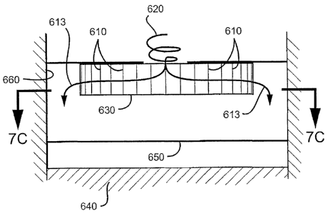
In Figure 7A, ?B and 7C, a rough distribution apparatus 600 contains a
plurality of
chevron-type vanes 6I0. The vanes are disposed between an outlet of a mixing
apparatus 620
and a splash deck 630. The presence of the splash deck 630 forces the fluid
exiting the mixing
apparatus to flow outward through the passageways 612 formed by chevron-type
vanes 610
along paths 613. The splash deck 630 is preferably imperforate, but may
contain orifices (not
shown) to allow a portion of the fluid to pass downward onto the subsequent
distribution tray
650 (which maybe the final distribution tray).
By way of reference, Figure 7B depicts catalyst bed 640 below subsequent
distribution
trays) 650, and reactor wall 660.
xn a preferred embodiment, the chevron-type vanes 610 are positioned below the
substantially imperforate floor of a mixing chamber (not shown), above a
substantially
imperforate splash deck 630, and surround the outlet oriflce(s) 620 of an
upstream mixing
chamber (not shown). The vane passageways 612 thereby formed cause the fluids
flowing
therethrough to change directions preferably at Ieast two times and provide
the sole means of
~o
CA 02554643 2001-04-24
WO ll2/OSt,3(1 PCT/US01/13~13C
fluid communication between the upstream mixing chamber and the downstream
subsequent
distribution tray 650. The chevron-type vanes 610 result in a more uniform
velocity profile of
the fluid exiting the vane passageways 612, thereby providing more effective
rough distribution
of the fluid to the subsequent distribution tray 650. When used in conjtmction
with a mixing
chamber that swirls the fluids being mixed therein, the chevron-type 610 vanes
also serve to
reduce the tangential component of the fluid velocity. When arranged in
circular layout that is
concentric with a central outlet orifice of the mixing chamber, the chevron-
type vanes 610
promote a liquid discharge pattern, exiting the vane passageways 612, such
that the liquid is
supplied to the subsequent distribution tray 650 in an annular ring (not
shown). This annular
ring supply pattern is an exhemely effective method of supplying liquid to the
subsequent
distribution tray 650, provided that the diameter of the ring produced by the
liquid is near
optimal. The optimal ring diameter is dependent upon the geometry of the final
distribution tray
650 and can be determined by hydraulic calculations. Although chevron-type
vanes have been
depicted in Figures 7A, 7B, and 7C, other flow redirecting-type vanes have
been contemplated.
1 S Several examples are depicted in Figures 8 and 9.
In Fibure 8, wave plate-type vanes 710 are spaced apart to form vane
passageways 712,
the passageways providilig a flow path 713 for fluids to pass theretluough.
In Figure 9, staggered channel-type vanes 810 are spaced apart to form vane
passageways 812, the passageways providing a flow path 813 for fluids to pass
therethrough.
Thus, specific embodiments and applications of mixing and distributing fluids
have been
disclosed. It should be apparent, however, to those skilled in the art that
many more
modifications besides those already described are possible without departing
from. the inventive
concepts herein. The inventive subject matter, therefore, is not to be
restricted except in the spirit
of the appended claims. Moreover, in interpreting both the specification and
the claims, all terms
should be interpreted in the broadest possible manner consistent with the
context. W particular,
the terms "comprises" and "comprising" should be interpreted as referring to
elements,
components, or steps in a non-exclusive manner, indicating that the referenced
elements,
components, or steps may be present, or utilized, or combined with other
elements, components,
or steps that are not expressly referenced.
m