Note: Descriptions are shown in the official language in which they were submitted.
CA 02554833 2006-08-03
POWER LEVER
SPECIFICATION
This invention relates to a perpetual motion machine ('Weight Motor'). In
previous
attempts, weights, and gears and cogs, and various other paraphernalia, have
found a
thousand ways to resist the desired effect. In this invention, the 'wheel
within a wheel,
within a wheel' approach is taken.
In drawings which illustrate embodiments of the invention in Canadian
Application
number 2545253, Figure 1 is an elevation 'in X-ray' of a two-sided* single god-
wheel
motor, bare of teeter arms, smaller internal gears, and pressure wheels;
Figure 2 is this embodiment and elevation with the elements mentioned above in
place;
Figure 3 is a top view of this embodiment in the same scale, through an
equatorial
section;
Figure 4 is an enlargement of Figure 3.
In drawings which illustrate addenda embodiments of the invention,
Figure 5 is an elevation in X-ray showing primary wheels in an embodiment
which does
not require intermediate bridle elements: the harness chain travels about the
distal edge of
the cupid wheel;
Figure 6 is a top view through a'with cupid' motor equatorial, showing where
chains
exist on their respective wheels;
Figure 7 is a top view of a'without cupid' motor indicating where the tug set,
and the
angel set, of teeter arms exist;
Figure 8 is a top view of the embodiment shown in Figure 7, indicating where
the chains
would exist;
Figure 9 is an end view of a'non cupid' motor, indicating where the tug
teeters, and the
angel teeters exist;
Figure 10 is an end view of the embodiment indicated in Figure 9, showing how
the
multi-strand chains are engaged;
Figure 11 is an end view of the embodiment shown on figures 9, and 10, except
that it has
extra harness sprockets to help to keep the chain from the forge and tug union
from
wracking/distorting too much, and it has an additional brave sprocket-to-crib
sprocket
return;
Figure 12 is an end view which indicated how the chains in Figure 11 would be
situated;
Figure 13 is an X-ray elevation of the embodiments in Figures 10, 11, and 12;
Figure 14 is a top view through the motor equatorial showing a separate cupid
sprocket
complement on each of the angel shafts;
Figure 15 is an elevation in X-ray, showing the placement, and relative
length, of the
angel teeters;
Figure 16 is an elevation in X-ray, showing the placement, and relative
length, of the tug
teeters;
Figure 17 is an end view of a cupid motor, showing that larger (brave)
sprockets may be
used from the harness shaft when the cupid sprockets to the harness wheels are
smaller
than the forge wheels;
Figure 18 is the embodiment shown in Figure 17, which the chains installed;
CA 02554833 2006-08-03
Figure 19 is an elevation in X-ray, of the primary wheel, and their relative
placement, in a
motor which uses only one angel shaft and tug shaft system;
Figures 20 to 24 are elevations which indicate some of the force sources which
can be
utilized in order to actuate the motor (as also found in the previous patent
application):
Figure 20 is a schematic of the tug teeter arms (rack arms) of an embodiment
being
moved by means of either hydraulic, or pneumatic, jacks;
Figure 21 is a schematic of the tug teeter arms (rack arms) of an embodiment
being
moved by means of electro-magnets which are controlled through a switch box in
the
foreground (where the toggle switch is here found in the neutral position);
Figure 22 is a schematic of the tug teeter arms (rack arms) of an embodiment
being
moved by means of a rope and pulley system;
Figure 23 is a schematic of the tug teeter arms (rack arms) of an embodiment
being
moved by means of a weight/mass being applied to one end of the rack;
Figure 24 is a simplified elevation of an embodiment being moved by a lever.
Figure 25 is an elevation indicating the angel teeter carriage applied to the
god wheel
after major wheels have been installed (before the capping element has been
fastened to
each of them).
Figure 26 is an end view of a single god wheel, non-cupid embodiment,
indicating how
two angel shafts are necessary on each side of the god shaft-one on each side
of the god
wheel-and a three-strand chain is required so that angel sprockets can embrace
the chain
on both sides of the god sprocket. Also shown is how only a single tug shaft
is required
on each side of the god shaft, and is supported by its bearings ahead of the
god wheel.
(Not shown are the teeter arms and teeter cross members.)
Figure 27 is an end view of the embodiment shown in Figure 26, with chain
installed.
* The term, 'two-sided' in this context means: having angel, and forge wheels
et al, on
both opposite sides of the god shaft. le. One set moves slightly upward while
the
other set moves slightly downward.
The motor illustrated in Figures 1 to 4 includes a central god shaft 1, on
which is fixed a
very large (god) sprocket 3. The god sprocket engages the middle row of a
triple-strand
compliment of roller chain 11, such that there is only enough chain to
perfectly
encompass the sprocket, and such that an empty strand of chain protrudes over
each side
of the very large sprocket. Teeter arms 17, hang, and balance, from the god
shaft 1, such
that two arms (called angel arms 17) extend to both sides of the god shaft and
reach to
shafts 18, on each of which are fastened a large (angel) sprocket 9 on one
end, and a
smaller (cupid) sprocket 10 found between the teeter 'angel' arms. The large
(angel)
sprocket 9 engages on its distal side, a protruding strand of the god chain
11, and the
smaller (cupid) sprocket 10 engages a (harness) chain 13 on the side proximal
to the god
shaft 1. The harness chain 13 travels to large harness sprockets 5 whose
shafts 4 are
fixed, one above and one below the compass of the god wheel, such that the
cycle of the
harness chain describes an 'hourglass' profile.
CA 02554833 2006-08-03
[In this case, the size ratio of the angel sprockets to the god sprocket is
the same as the
ratio of the cupid sprocket to the harness sprockets.]
A bolster rim 23 is fixed to each angel sprocket 9 and extends beyond the
diameter of the
angel to attach to a (forge) internal gear 8, such that it does not interfere
with the free
engagement of the sprocket with the god chain 11. Other sets of teeter arms,
called tug
arms (or 'long arms') 20 (two on each side of the god wheel 3) pivot about the
god shaft
1, and reach beyond the angel shafts 18, to carry the tug shafts 6. On each
tug shafts 6 is a
tug pinion 7 which engages the forge (internal) gear 8 at its particular site.
The tug arms
20 have a freeway slot 19 cut into them which allows them to move
independently of the
movement of the angel arms 17 and shafts 18. At the ends of the longer tug
arms 20 are
cross members 21 which cause all such tug arms to move up and down in concert.
The
tug gear/pinion 7 engages the distal side of the forge (internal) gear.
Neither the angel
shafts 4, nor the tug shafts 6 extend to any wall; but the god shaft 1 and the
harness shafts
4 extend beyond an inner crib wall 25, and into/through the outer walls 26 at
both ends of
the motor, and rest in bearings/(journals) 2. (The inner wall 25 at one end
and the outer
wall at that same end, in conjunction with the side panel 27, form an inner
(crib) chamber
24 where a feedback loop can be completed.) Another (bridle) shaft 28 is
placed between
the outer (end) wall 26 and the inner (crib) wall of the crib 24, and near the
god shaft 1,
such that a bridle gear/pinion 16 on the bridle shaft 36 engages a small crib
gear/pinion
22 on the god shaft 1. A small (brave) sprocket 14 on one of the harness
shafts 4 connects
chain 12 to the bridle sprocket 15 on the bridle shaft 36. The bridle pinion
16 on the
bridle shaft 36 turns with the crib pinion 22 on the god shaft 1.
When pressure is applied to either (or to both, in opposite directions) end/s
of the long
tug arms 20 one end rises slightly and the other falls slightly, and force is
sent via the tug
wheels 7 against the forge (internal gear) wheels 8, which is conveyed
significantly to the
distal sides of angel sprockets 9 and to the god wheel 3. The large god wheel,
and small
crib wheel (3 and 22) turn, forcing the bridle gear 16 on the bridle shaft 36
to turn,
forcing the bridle sprocket 15 on the bridle shaft to turn, forcing the brave
sprocket 14 to
turn, forcing the harness sprockets 5 to turn, forcing the cupid wheels 10 to
turn, forcing
the angel sprockets 9 to turn, yet stay in place. And the cycle repeats until
pressure is
removed from the long (tug) arms 20.
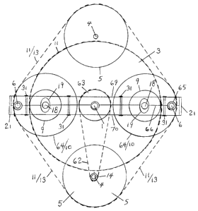
Figure 5 (and subsequent embodiments) indicates a simpler, more efficient
design insofar
as it no longer uses any of: crib wall, bridle shaft, bridle sprocket, bridle
pinion, nor crib
pinion, but instead sends chain directly from the brave sprocket 14 on a
harness shaft 5,
to the crib sprocket 63 on the god shaft 1 via a long bridle chain 62. This is
accomplished
by sending harness chain from the distal edge of the cupid sprockets, instead
of from the
proximal edges of said cupid sprockets.
Figure 6 is a top view of an equatorial section of an embodiment having two
god wheels
3, and indicating sites where multi-strand chain 11 is employed to effect the
necessary
connections.
Figure 7 is a top view of an equatorial section having two god wheels,
indicating how the
angel teeter arms 17 actually extend beyond the length of the tug teeter arms
20, so that
both sets of arms may be joined and mutually reinforced by cross members 21.
It also
indicates a wall-to-wall joining element 71 extending from one end wall 26 to
the other
end wa1126.
CA 02554833 2006-08-03
In this case, the forge wheels 10 are now sprockets 64, and the tug wheels 7
are now tug
sprockets 65.
Figure 8 is a top view of an equatorial section having two god wheels,
indicating a set of
angel teeter arms shortened at one end, and a set of tug arms lengthened to
permit more
leverage against the cross arm 21 of the tug arms set at the force site 72.
This drawing
also indicates bolt sites 31 which fasten the capping elements of the teeter
arms to their
respective carriage elements.
Figure 9 is an end view of an embodiment which uses the forge wheels 64 both
as forge
sprockets and as cupid sprockets 10.
Figure 10 is an end view of the embodiment shown in Figure 9, with the
necessary multi-
strand chains 11 installed, and with the bridle chain 62 from the brave
sprocket 14 to the
crib sprocket 63.
Figure 11 is an end view of embodiment similar to the embodiment shown in
Figures 9
and 10, except that it has extra harness sprockets 5 to receive chain, and an
extra brave
sprocket 14 and crib sprocket 63 to better accommodate received torque.
Figure 12 is the embodiment illustrated in Figure 11, with chains 11, 11/13
and 11/62
installed, going between god wheel and angle wheel, forge-tug pairing and
harness
pairings, and brave wheel and crib wheel pairings.
Figure 13 is an elevation in X-ray, of the embodiment shown in Figures 11 and
12.
Figure 14 is a top view of an equatorial section having two god wheels,
indicating
separate cupid sprockets 10, in which case single strand chain 13 may be used;
Figure 15 is an elevation showing the relative length of the angel teeter 17
and how it is
divided into two sections: a lower, carriage section 68, and an upper capping
section 67,
and fastening bolts 31, with a seam 66 showing between them;
Figure 16 is an elevation showing the relative length of the tug teeter 20 and
how it is
divided into two sections: a lower, carriage section 70, and an upper capping
section 69,
and fastening bolts 31 with a seam 66 showing between them, and clearance
slots 19
between them too;
Figure 17 is an end view of an embodiment having sets of cupid sprockets 10
which are
smaller than the forge wheels 64, and which thereby allow the brave sprockets
14 to be
larger than is the case when forge wheels also serve as cupid wheels;
Figure 18 is an end view of the embodiment shown in Figure 17, with the
necessary
chains installed: 11, 13, 11, 62/11, 11, 13, and 11;
Figure 19 is a one-sided motor which uses the forge wheel 64 as the cupid
wheel 10 too;
The following illustrations (20 to 24) are also found in the first application
(#2545253)
with some changes to their numbering:
The embodiments featured in Figure 20 use either a hydraulic pump 51 to pump
fluid to
one of the jacks 50, and simultaneously away from its opposite jack, whose
piston rods
60 move up or down respectively against the long teeter arms 20; or a
pneumatic pump
53 to pump air via hose 54 to one of the jacks 52, and simultaneously away
from its
opposite jack, whose piston rods 60 move up or down respectively against the
long teeter
arms 20.
CA 02554833 2006-08-03
The embodiment in Figure 21 uses electro-magnets 55 to move the long teeter
arms 20.
Fixed to the ends of the teeter arms 20 on both top and bottom sides [if we
wish the
motor to rotate in both directions] are placements of magnetically attractive
material 56.
Either one set of opposite magnets (x) is electrified via wires 57, or the
other set (y) is, or
the toggle switch 58 is left in a neutral, non-charging position (in which it
is here shown).
The embodiment in Figure 22 uses a line 44 and pulley 43 system, by which to
exert
force on either of the long tug arms 20, or upon the cross member 21 which
joins them.
The embodiment in Figure 23 uses a line 44 and weight/mass 45 by which to
exert force
on either of the long (tug) teeter arms 20.
The embodiment in Figure 24 uses a separate leveraging arm 47, to impose
additional
force against the tug teeter arms 20 at their receptor site (72) of their
cross members 21;
Figure 25 is an elevation in schematic indicating a lower section 68 of an
angel teeter
arm, where it engages the god shaft 1 while carrying its angel shaft loads,
and before
being connected to its upper half section.
Figure 26 is an end view of a single god wheel, non-cupid embodiment,
indicating how
two angel shafts 18 are necessary on each side of the god shaft 1-one on each
side of the
god wheel 3-and a three-strand chain 11 is required so that angel sprockets
can embrace
the chain on both sides of the god sprocket. Also shown is how only a single
tug shaft 6 is
required on each side of the god shaft, and is supported by its bearings 2
outside the reach
of the god wheel.
(Not shown in this case are the teeter arms and teeter cross members.)
Figure 27 is an end view of the embodiment shown in Figure 26, with chain
installed.
CA 02554833 2006-08-03
God-Wheel Chain Motor with Power Lever Addenda
List of Parts
1 god shaft
2 bearing
3 god wheel (This may be a disc to which internal gears are affixed; or a
large
sprocket to which multiple-strand roller chain is applied; or some other large
wheel which can support an overlapping rim strip to which some other sort of
non-skid wheel may roll.)
4 harness shaft
harness sprocket wheel
6 tug shaft
7 tug pinion gear
8 forge wheel internal gear
9 angel wheel (gear or sprocket)
cupid wheel (sprocket)
11 multi-strand roller chain (or another continuous, re-connectable/patchable,
cable, strap, belt)
12 bridle chain (traveling between the bridle sprocket, and the brave sprocket
on
the harness shaft)
13 harness chain
14 brave sprocket
bridle sprocket
16 bridle pinion
17 teeter 'angel' arm from god shaft to angel shaft/s
18 angel shaft
19 freeway slot (in tug teeter arms, allowing it/them to arc up or down
independently of the travel of the angel arms. The size has been exaggerated
for illustrative purposes.)
tug teeter arms
21 cross member (connecting the force arms so that they move in concert)
22 crib gear (on the god shaft within the crib walls)
23 rim bolster (from near the rim of each greater angel to a face of the forge
wheel)
24 crib space (formed by inner and outer end walls of the motor, across which
walls one or more ante shaft/s extend/s, and support/s one or more crib
sprocket and gear set/s.
crib wall
26 end wall
27 side paneling
28 bolster plate (fixed to an angel hub, (and/or a cupid hub,) instead of
using a
rim bolster. This option obviates the need to take the god wheel hub diameter
into account, so that the outer diameter of the forge wheel may be greater.)
29 access window in side/s of motor, for installation and maintenance purposes
teeter rack
CA 02554833 2006-08-03
31 fastening bolts
32 outrigger arms (outside the end walls)
33 reaching arms (reaching in from the teeter rack)
34 carriage rack
35 tug unit
36 bridle shaft
37 sending sprocket (to an outside consumer)
38 sending chain (or other belting)
39 internal gear/s (attached to god disc)
40 sending gear (to an outside receiving pinion-belonging to a gear box,
dynamo, etc.)
41 counter weight (used to offset gravity when a single sided chain motor is
employed)
42 wheel hub (whether sprocket or gear)
43 pulley
44 (pulley) line/cable
45 weight/mass source
46 spring
47 lever arm
48 travel slot in lever arm (which engages 'handle' of teeter carriage/rack)
49 fulcrum
50 hydraulic jack
51 hydraulic pump
52 pneumatic jack
53 pneumatic pump
54 feeder tubing/hose (to or from jack)
55 magnet
56 magnetically attractive material
57 electrical wire/cable
58 toggle switch (shown in neutral position)
59 electrical switch box (shown in foreground/background format)
60 jack piston rod
61 slide platform (connected to outrigger arms)
62 long bridle (direct from brave sprocket to crib sprocket)
63 crib sprocket
64 forge sprocket
65 tug sprocket
66 seam/joint between cap and carriage elements of teeter arms
67 angel teeter cap
68 angel teeter carriage
69 tug teeter cap
70 tug teeter carriage
71 wall-to-wall connecting/reinforcing element
72 receptor site of imposed force