Note: Descriptions are shown in the official language in which they were submitted.
CA 02554863 2006-07-28
WO 2005/073629 PCT/CA2005/000110
DIRECTLY VIEWABLE LUMINAIRE
FIELD OF THE INVENTION
The present invention pertains to lighting and in particular to a directly
viewable
luminaire.
BACKGROUND OF THE INVENTION
Due to their higher overall luminous efficacy and flexibility for achieving
various light
patterns, luminaires using high-flux LEDs are fast emerging as the preferred
lighting
architecture over conventional light fixtures. These luminaires are
increasingly used in a
wide range of applications where high light output is required, such as
theatrical
spotlights, high-power flashlights, and automotive headlights. They are also
penetrating
mainstream commercial applications like task lights, accent lights, wall
washing,
signage, advertising, decorative and display lighting, cove lighting, wall
sconces, facade
lighting, and custom lighting.
The ability to maximize light output from a luminaire increases energy
efficiency and
reduces production and maintenance costs. Typically, a high flux LED luminaire
comprises a plurality of high flux light-emitting diodes, as well as a power
supply unit
for excitation of the light-emitting diodes. Through maximizing the light
output in the
desired light pattern, power consumption for these light-emitting diodes may
be reduced.
Otherwise, additional power would be needed to overcome these light losses.
A primary concern in the design and operation of high flux LED luminaires is
thermal
management. The luminous intensity of a light module is quite often a strong
function
of its operational temperature. High flux LED luminaires tend to generate
large amounts
of heat during operation. Not only does this heat reduce the light output of a
light-
emitting diode, but it can also reduce the reliability and the life expectancy
of the
lighting module, due to premature failure of one or more light-emitting
diodes.
Accordingly, heat dissipation often becomes a critical design consideration as
the
undesirable heat negatively affects the performance of the luminaire.
1
CA 02554863 2006-07-28
WO 2005/073629 PCT/CA2005/000110
Various heat dispersive systems such as heat sinks, use of metal-core printed
circuit
boards, heat absorbers or a combination thereof have been proposed. However,
the
existing heat dissipation systems generally spread the heat from a hot spot to
another
location for dissipation without coolth collection.
For example, U.S. Patent No. 6,211,626 to Lys et al. discloses a heat
dissipating housing
made of a heat-conductive material for containing a lighting assembly therein.
The heat
dissipating housing contains two stacked circuit boards holding respectively a
power
module and a light module. The light module comprises a light emitting diode
(LED)
system mounted on a heat spreader plate that is in contact with the housing
for
dispersing away the heat generated by the LED system that is in thermal
contact with the
plate, thereby conducting heat towards the housing.
A particular advantage of the Lys et al. heat spreader is that when the heat
source is
located proximate to the center of a circular plate, the temperature at the
boundary
thereof is substantially constant. Accordingly, the heat spreader distributes
the heat
evenly to a thermally connected housing which ejects the heat into the
surrounding
environment. However, this heat dissipation system may not work well with
housings
which exhibit hot spots when dissipating heat.
U.S. Patent No. 4,729,076 to Masami et al. teaches a heat dissipation
mechanism for an
LED traffic signal. A heat absorber such as a heat conductive resin in thermal
communication with a printed circuit board on the other side of which an array
of LEDs
is formed, is disclosed. A finned heat sink is in thermal contact with the
heat absorber.
The heat absorber collects the heat generated by the array of LEDs and
provides a
conductive path for the heat towards the heat sink for dissipation into the
ambient
environment. The disclosed heat absorber, however, is typically a poor heat
conductor
and does not provide for optimal heat transfer to the heat sink.
U.S. Patent No. 5,173,839 to Metz, Jr. is directed to an LED array thermally
bonded to a
strip of alumina that is bonded to a heat sink bonded via thermally-conductive
tape.
Similarly, U.S. Patent No. 5,857,767 to Hochstein teaches mounting LEDs on a
metal
core PCB having an integral heat sink with electrically and thermally
conductive epoxy.
2
CA 02554863 2006-07-28
WO 2005/073629 PCT/CA2005/000110
The optical performance of a light-emitting diode is another important
consideration
when designing high flux LED luminaires. The light-emitting diode used to
generate
light often has special emission characteristics. Optical devices such as
reflectors or
lenses have specific geometries which enable them to ameliorate the
performance of the
light-emitting diode. The performance of the LED can be improved by a
judicious
choice of optical devices adapted to particular output characteristics of the
light-emitting
diode.
Traditional directly viewed luminaires use light-emitting diodes with no
optics and a
housing comprising a transparent shield typically made of glass or plastic to
protect the
light-emitting diodes against natural elements. The transparent shield
effectively blocks
the light-emitting diode's output and reduces the overall illumination
luminous flux
output of the luminaire. Moreover, the individual light-emitting diodes are
often visible
through the transparent shield and could appear as point sources. This can
further
reduce light output uniformity and can cause a "pearl necklace" effect, which
is
undesirable.
A number of solutions have been proposed to alleviate the undesirable pearl
necklace
effect. One solution seeks to improve light output uniformity by providing a
diffuse
transparent shield surrounding the light-emitting diodes. However, in order to
achieve
good levels of luminous uniformity, the light-emitting diodes must be spaced
relatively
close with respect to one another. Due to design limitations, this solution is
often not
available, especially when using high flux light-emitting diodes whereby the
close
proximity of the light-emitting diodes creates a high concentration of
unwanted heat.
This problem is further exacerbated in luminaires having a plurality of light-
emitting
diodes of different colour combinations for colour mixing, where the distal
spacing
between the various light-emitting diodes must be minimized to generate a
desired
resultant colour.
Therefore there is a need for a new design for a directly viewable luminaire
that can
address these thermal and optical deficiencies identified in the prior art.
This background information is provided for the purpose of making known
information
3
CA 02554863 2006-07-28
WO 2005/073629 PCT/CA2005/000110
believed by the applicant to be of possible relevance to the present
invention. No
admission is necessarily intended, nor should be construed, that any of the
preceding
information constitutes prior art against the present invention.
SUMMARY OF THE INVENTION
An object of the present invention is to provide a directly viewable
luminaire. In
accordance with one aspect of the present invention there is provided a
luminaire
comprising a housing defining a first internal compartment containing one or
more light-
emitting elements mounted on a base connected to the housing, the housing
further
defining a second internal compartment containing electronic driver means
coupled to
the one or more light-emitting element for providing controlled electrical
energy to the
one or more light-emitting elements, said first compartment is thermally
separated from
the second compartment.
In accordance with another aspect of the present invention there is provided
luminaire
comprising: a housing defining a first internal compartment containing one or
more
light-emitting elements mounted on a planar support connected to the housing,
the
housing further defining a second internal compartment containing electronic
driver
means coupled to the one or more light-emitting elements for providing
controlled
electrical energy to the one or more light-emitting elements, the first and
second internal
compartments being thermally isolated from one another; and an optical means
coupled
to the housing for manipulating light emitted by the one or more light-
emitting elements,
said optical means comprising first and second diffuser elements positioned
coaxially in
a spaced apart configuration.
In accordance with another aspect of the present invention there is provided
an optical
device for use with a luminaire including two or more light-emitting elements,
the
optical device comprising: a first diffuser element configured to be
positioned proximate
to the two or more light-emitting elements, said first diffuser for diffusing
emitted flux
from the light-emitting elements; and a second diffuser element having a
length and
positioned in coaxial spaced apart alignment with the first diffuser, said
second diffuser
for providing secondary diffusion of the emitted flux; thereby enabling
creation of a
substantially constant luminance along the length of the second diffuser.
4
CA 02554863 2006-07-28
WO 2005/073629 PCT/CA2005/000110
BRIEF DESCRIPTION OF THE FIGURES
Figure 1 shows an isometric view of a luminaire according to one embodiment of
the
present invention.
Figure 2 illustrates an isometric exploded view of the embodiment of Figure 1.
Figure 3 shows a cut-away isometric view of the upper compartment of the
luminaire of
the embodiment of Figure 1.
Figure 4 is a cross sectional view of the H-shaped supporting base according
to the
embodiment of Figure 1.
Figure 5 is a cross sectional view of the U-shaped base cover of the
embodiment
according to Figure 1.
Figure 6 shows a side cross-sectional view of the luminaire of Figure 1 taken
along the
line A-A.
Figure 7 shows an isometric view of a luminaire with integrated light-emitting
elements
arranged in a matrix layout, according to one embodiment of the present
invention.
Figure 8 illustrates a cross sectional view of the luminaire illustrated in
Figure 7 taken
along the line B-B.
Figure 9 illustrates an isometric view of a luminaire with integrated light-
emitting
elements arranged in a linear layout according to one embodiment of the
present
invention.
Figure 10A illustrates a combination of blue, green and red light-emitting
elements
arranged in a linear fashion according to one embodiment of the present
invention.
Figure I OB shows the side view of Figure 10A.
5
CA 02554863 2006-07-28
WO 2005/073629 PCT/CA2005/000110
Figure 11 is a cross sectional view of an optical device according to one
embodiment of
the present invention.
Figure 12 is a cross sectional view of an optical device according to another
embodiment
of the present invention.
Figure 13 illustrates is a magnified cross-sectional view of a variant of the
first diffuser
of the optical device according to one embodiment of the present invention.
DETAILED DESCRIPTION OF THE INVENTION
Definitions
The term "light-emitting element" is used to define any device that emits
radiation in the
visible region of the electromagnetic spectrum when a potential difference is
applied
across it or a current is passed through it, for example, a semiconductor or
organic light-
emitting diode (LED or OLED, respectively) or other similar devices as would
be
readily understood. It would be obvious to one skilled in the art that
elements that emit
other forms of radiation such as infrared or ultraviolet radiation may also be
used if
desired in the present invention in place of or in combination with light-
emitting
elements.
Unless defined otherwise, all technical and scientific terms used herein have
the same
meaning as commonly understood by one of ordinary skill in the art to which
this
invention belongs.
The present invention arises from the realization that improved light output
can be
achieved by heat dissipation and improved light reflection. Accordingly, the
degradation of flux as a function of increasing temperature in luminaires can
be avoided
by compartmentalizing and thermally isolating the heat generating elements
such as the
driver, power supply and the light-emitting elements into two or more
thermally separate
compartments within the luminaire. The compartmentalized components comprise
thermally conductive material in contact with the luminaire housing which
incorporates
a finned or undulating surface to improve coolth collection. Moreover, an
optical device
comprising two linear diffuser elements that can be used to further improve
the light
6
CA 02554863 2006-07-28
WO 2005/073629 PCT/CA2005/000110
emission characteristics of the light-emitting elements thereby providing a
directly
viewable luminaire wherein the illumination produced by point light sources
appears
uniform along the length of the luminaire.
By heat sinking the light-emitting elements to a material with high thermal
conductivity
such as aluminum, the operating temperature of the light-emitting elements can
be
reduced and the light output can be improved. Similarly, the heat generating
components of the power supply unit and controller subsystems can also be heat
sinked
to a material of high thermal conductivity (such as aluminum, copper, silver,
a thermally
conductive polymer or the like) in order to dissipate the heat that they
generate.
The present invention provides a luminaire comprising a housing having
thermally
separate compartments for an electronics portion and a lighting portion. These
thermally separate compartments can provide a means for providing thermal
isolation
between the respective components, namely the electronics portion and the
lighting
portion. In this manner thermal interaction between these portions can be
reduced,
thereby improving performance of the luminaire. The lighting portion comprises
a
plurality of light-emitting elements and further includes optics for the
manipulation of
illumination created by the light-emitting elements. A power supply for supply
of
energy to the light-emitting elements and a controller for controlling
application of
energy from a power source to the light-emitting elements is provided in the
electronics
portion and these components can be thermally separated within the electronics
portion.
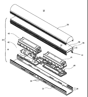
Reference is now made to Figure 1, which illustrates a luminaire pursuant to
one
embodiment of the present invention. The luminaire 10 includes a generally
elongated
housing 20 with separate upper and lower compartments 22, 24 respectively. The
lower
compartment 24 includes the power and control modules (not shown). The upper
compartment 22 contains a plurality of light-emitting elements 33 mounted on a
printed
circuit board (PCB) or metal-core printed circuit board (MCPCB) 32 which is
mounted
on an H-shaped supporting base 30. The supporting base 30 includes upwardly
projecting elements 35, 36 which form the walls of the upper compartment 22,
and
downwardly projecting elements 37, 38 which form a portion of the lower
compartment
24.
7
CA 02554863 2006-07-28
WO 2005/073629 PCT/CA2005/000110
It will be appreciated by one skilled in the art that the boards 32 can be
attached or held
to the base 30 in a number of ways known to those skilled in the art
including, but not
limited to gluing, screwing or bolting, for example. Further, it will be
appreciated by
one skilled in the art that the board 32 and the light-emitting elements 33
can be
electrically connected in a number of ways including, but not limited to,
electrically
connecting wires from a power supply unit and a controller (not shown) to wire
leads
located on the board 33 which includes circuit traces to the individual light-
emitting
elements. To further take advantage of the luminaire housing's 20 unique heat
dissipation properties, the thermal connection between the board 32 and the
base 30 can
be enhanced through the use of a heat conductive adhesive tape or thermal
grease, for
example. A heat conductive adhesive tape or thermal grease has heat conduction
properties that can enhance heat transfer and can enable one to increase the
contact
surface area between the board 32 and the base 30.
The supporting base 30 is advantageously constructed from a heat-conducting
material,
for example aluminum, and comprises a finned or undulating surface 34 to
dissipate the
thermal radiation from the light-emitting elements 33 generated during their
operation.
This heat can degrade the luminous performance of the light-emitting elements
33 and
can reduce the life expectancy thereof. Accordingly, if an optimum performance
of the
light-emitting elements in terms of their luminous flux is to be achieved,
thermal
management of the light-emitting elements 33 is required to remove the excess
heat
away therefrom. The supporting base 30 can effectively act as a heat sink (or
source of
coolth) to conduct the heat away from the light-emitting elements 33 to the
exterior, and
the finned or undulating surface 34 can enhance the efficiency of this
radiator effect.
Figure 2 illustrates an exploded view of the luminaire 10 of Figure 1. The
upper
compartment 22 of the integrated luminaire housing 20 further includes a
transmissive
cover plate 26 which can be a translucent planar diffuser that can be bonded
to the
upwardly projecting elements 35, 36 using a sealant adhesive such as silicone
to form a
waterproof module. This sealed light portion forms the upper compartment 22 of
the
integrated luminaire housing 20. Advantageously, the lighting portion can
comprise an
elastomeric seal that allows for differential thermal expansion between the
transmissive
cover plate and the base formed from another type of material. This type of
8
CA 02554863 2006-07-28
WO 2005/073629 PCT/CA2005/000110
configuration can enable the use of the luminaire according to the present
invention in
regions having thermal gradients, for example.
Figure 3 illustrates a cut-away perspective view of the upper compartment 22
formed as
a sealed light portion according to the embodiment of Figure 1. A barrier or
end cap 57
can be positioned at each end of the light portion in order to provide a means
to seal the
upper compartment 22. The barrier may be covered with a sealant 60 for example
silicone or other suitable sealant, to hermetically seal the upper compartment
22, for
example. Furthermore, as shown in Figure 3, the heat sinking base 30 can
further
include a plurality of air vents 27 for improved ventilation and heat
dissipation within
the lower compartment.
The lower compartment 24 of the integrated luminaire housing 20 of Figure 2
comprises
a power supply unit (PSU) 40 and a controller 42 such as a microcontroller in
electrical
communication with the light-emitting elements 33 to supply electrical power
and
control the luminous intensity of the light-emitting elements 33. Each of the
PSU 40
and the controller 42 are surrounded by a U-shaped base cover 31 made of a
highly
thermally conductive material such as aluminum or the like to expel the heat
generated
by the PSU 40 and the controller 42 into the ambient environment. The base
cover 31
may be coupled to the base 30 using interlocking elements that are integrated
within the
base and the base cover. For example as illustrated in Figures 4 and 5,
downwardly
projecting elements 37 and 38 can be specifically designed to mate with
elements 110
and 120, respectively provided on the base cover. In order to secure this
mating
connection to longitudinal slip, a securing connection between the base and
the base
cover may be provided in the form of one or more screws or the like, for
example. This
form of interconnection between the base and the base cover may provide access
to the
PSU 40 and the controller 42 units without the need for completely dismantling
the
luminaire. As illustrated in Figure 2, the base cover 31 also includes a
finned or
undulating outer surface 39 to improve the cooling effect of the base cover
31. In one
embodiment, the underside 100 of the base 30 may further comprise fins or
undulations
in order to further enhance heat dissipation of the base 30. In one
embodiment, the
protrusions 110 and 120 of the base cover 31 and/or the downwardly projecting
elements 37 and 38 of the base 30 comprise openings enabling the entry of air
into the
lower compartment for enhancing the thermal dissipation provided by the fins
or
9
CA 02554863 2006-07-28
WO 2005/073629 PCT/CA2005/000110
undulations on the underside 100 of the base. This feature is illustrated in
Figure 8
which illustrates one embodiment of the present invention, wherein the base 54
comprises fins or undulations 50, to dissipate heat generated by the light-
emitting
elements thermally connected thereto, while the base cover 56 also comprises
fins or
undulations 52 for the provision of heat dissipation for the power supply and
controller
unit, for example.
The electronic subsystems PSU 40 and controller 42 may include associated heat
sinks
(not shown) and are preferably arranged in the integrated luminaire housing 20
so that as
much surface area of their associated heat sinks as possible is exposed to the
"cooler"
external ambient environment to assist heat flow out of the luminaire. In the
presently
described embodiment of the invention, a power supply enclosure 41
manufactured from
a material having low thermal conductivity, such as plastic is attached to the
supporting
base 30 in order to provide further thermal shielding for the various
components of the
luminaire 10 from the heat generated by the PSU 40. Similarly, a controller
enclosure
43 covers the controller 42 and thermally isolates the components of the
luminaire 10
from undesirable heat generated by the controller 42 during operation. The
addition of
the enclosures 41 and 43 can channel the heat from the PSU 40 and controller
42
through the more thermally conductive heat sink associated with the base cover
31 to the
ambient environment outside. It is also observed that the enclosures 41 and 43
can
further protect the PSU 40 and the controller 42 from exposure to natural
elements such
as rain or humidity as these covers can be sealingly connected to the base
cover, for
example through the use of a gasket or other sealing means, for example a
sealant.
Advantageously, the thermal separation between the compartments 22, 24 may be
further enabled by providing an additional thermal barrier (not shown) between
these
compartments 22, 24. In addition a heat shielding metallic or plastic barrier
can provide
a thermal barrier between the PSU 40 and the controller 42 systems. In one
embodiment
the sealed light portion and the sealed PSU 40 and controller 42 portions are
then
assembled together so that their heat sinks form the base cover 31 of the
luminaire 10
allowing heat from within the luminaire 10 to flow to the cooler ambient air
outside the
luminaire 10
Based on the foregoing, it is therefore appreciated that the luminaire housing
of the
CA 02554863 2006-07-28
WO 2005/073629 PCT/CA2005/000110
present invention effectively provides for the operation of the light-emitting
elements at
a different temperature from the operation temperature of the PSU and the
controller.
This thermal separation is provided by the inclusion of separate compartments
for the
light portion and the electronics portion or power management unit to limit
the thermal
impact of one subsystem on another. The compartmentalization of the housing
into an
upper compartment and a lower compartment may enable operation of the light-
emitting
elements at a higher temperature while operating the power management unit at
a lower
temperature, for example due to the thermal separation thereof. Accordingly,
through
thermal separation, each subsystem can perform at a desired level while
limiting thermal
impact of one subsystem on another within the luminaire.
Reference is now made to Figure. 6, which shows a side cross-sectional view of
the
luminaire 10 along line A-A of Figure 1. The luminaire 10 shown in Figure 6
includes a
linear array of light-emitting elements disposed on a PCB thermally connected
to the H-
shaped base 30 at the approximate focus of a linear compound parabolic
collector 50.
The light-emitting element array can be red, green and blue light-emitting
elements or
other colours as would be readily understood. Using a combination of red,
green and
blue light-emitting elements 33a, 33b and 33c (shown in Figure 10A and in
elevation in
Figure 10B) mounted in a linear array, it is possible to achieve any desired
colour by
mixing the three colours using an optical structure comprising various
diffusing
elements. These diffusing elements can act as a mechanism to mix the three
colours,
and to display the mixed light as a uniform luminous object in brightness and
mixed
colour. It would be understood that more colours of light-emitting elements
could be
mixed if desired, for example the inclusion of amber light-emitting elements.
The linear
array of light-emitting elements may be arranged in repeating groups of blue,
green and
red light-emitting elements. In such a configuration, the order of the light-
emitting
elements within each group may be determined by the luminous distribution
characteristics of the light-emitting elements so as to maximize the
uniformity of
luminance of the luminaire.
In one embodiment of the invention illustrated in Figure 7, the light-emitting
element
array is laid out in a 2-dimensional matrix fashion on the heat sinking base
54 that
allows the base cover 56 of the luminaire 10 to be short and wide. In this
configuration,
the PSU 40 and controller 42 (not shown) can be placed side by side in the
lower
11
CA 02554863 2006-07-28
WO 2005/073629 PCT/CA2005/000110
compartment 24 of the housing 20 as illustrated in Figure 8, for example. In a
further
exemplary embodiment shown in Figure 9, the light-emitting elements are
arranged in a
linear fashion along the base 30, which allows for a longer thinner luminaire
10. In this
scenario, the PSU 40 and controller 42 (not shown) can be placed end to end in
a single
line along the length of the luminaire 10.
Referring back to Figure 6 in conjunction with Figure 2, the luminaire 10
further
includes an optical device 28 such as an optical diffuser that fits over the
upper
compartment 22 for collecting and reflecting light produced by the light-
emitting
elements 33. The optical device 28 includes a first and a second linear
hemispherical
optical diffuser 28a and 28b, respectively, to diffuse the emitted luminous
flux by the
light-emitting elements. A diffuser is a device which scatters incident
electromagnetic
radiation, including visible light, infrared and ultraviolet radiation by
means of diffuse
transmission or reflection into a variety of luminance distribution patterns.
The optical
device of the present invention is not limited to diffusers, and the optical
device 28 used
for the manipulation of light from the light-emitting elements may be in a
variety of
configurations and a combination of optical devices 28 may be used together to
provide
a desired luminous flux distribution. Optical device 28 may be used to
collimate light
from the light-emitting elements in a desired direction or diffuse the light
in a desired
direction, for example, thus providing a variety of desirable luminous flux
distributions.
The optical device 28 may further enhance the luminous flux characteristics of
the light-
emitting elements resulting in improved power efficiency, but also it can
serve to further
dissipate heat generated by the light-emitting elements through its structure.
An optical element 50 having a generally parabolic spectrally selective
reflective surface
is also disposed in the plane perpendicular to the collinear axes of said
diffusers 28a and
28b. Accordingly, the light from the different coloured light-emitting
elements in the
array is "collected" into the first diffuser 28a by the optical element 50
which can be for
example a collector. The optical element 50 can be designed to collimate the
emitted
flux from said light-emitting element array in a direction generally
perpendicular to the
linear axis of said optical element 50 and preferentially diffuse the flux in
a direction
generally parallel to the linear axis of said optical element 50, which could
be either
specular, diffuse or a combination of both. Another method of collecting the
light is to
use a lens that uses "total internal reflection" to efficiently couple the
light from the
12
CA 02554863 2006-07-28
WO 2005/073629 PCT/CA2005/000110
plurality of light-emitting elements in the array.
Various other non-imaging optical devices may also be used to enhance the
light flux of
the light-emitting elements. In another embodiment of the present invention, a
compound parabolic collector or similar non-imaging optical device can be used
as the
optical element 50, wherein the reflective surfaces of said device are
specularly
reflective. In another embodiment a compound parabolic collector or similar
non-
imaging optical device can be used as the optical element 50, wherein the
reflective
surfaces of said device comprise microreplicated or holographic optical
elements to
preferentially reflect the emitted flux of said light-emitting element array
to produce a
generally desirable luminous flux distribution. In yet another embodiment a
compound
parabolic collector or similar non-imaging optical device can be used as the
optical
element 50, wherein said device comprises one or a multiplicity of moulded or
extruded
plastic lenses.
In the presently described embodiment, the planar optical diffuser 26 is
disposed
coplanar to the first diffuser 28a which diffuses the emitted flux from light-
emitting
elements array outwardly towards the second diffuser 28b. As a result, the
flux may
appear to function as a secondary light source. The second diffuser 28b
located coaxial
to the first diffuser 28a further diffuses the flux and thereby appears to a
viewer to
possess approximately constant luminance along the length of the second
diffuser 28b
from all viewing directions of the luminaire 10. The planar diffuser 26 can
allow further
diffusion of the light enhancing the colour mixing. In an alternative
embodiment of the
present invention, a first hemispherical linear optical diffuser 28a or second
hemispherical linear diffuser 28b may be used wherein said types of diffusers
comprises
frosted glass; moulded, embossed, extruded, or formed plastic; or a
holographic diffuser.
Similarly, in one embodiment of the present invention, a first or second
hemispherical
linear optical diffuser 28a, 28b may be used whereby the diffuser 28a or 28b
comprises
a linear or elliptical holographic diffuser to diffuse the emitted flux of
said light-emitting
elements array in a preferred direction to produce a generally desirable
luminous flux
distribution. In another embodiment of the present invention, a first or
second
hemispherical linear optical diffuser 28a, 28b may be used wherein the
diffuser
comprises a circular holographic diffuser to improve the transmittance in
comparison to
frosted glass or bulk plastic diffusers. A first or second hemispherical
linear optical
13
CA 02554863 2006-07-28
WO 2005/073629 PCT/CA2005/000110
diffuser 28a, 28b having a linear pattern of grooves is embossed or moulded in
one or
both surfaces of the diffuser 28a, 28b may also be used. The first and second
linear
optical diffuser 28a, 28b may be co-extruded as a single component.
Figures 11 and 12 illustrate example configurations of the optical device
comprising
first and second diffusers, wherein the optical device can be mate with the
upwardly
projecting elements 35 and 36 of the base 30 thereby securing the optical
device to the
base. For example in Figure 11, the second diffuser 280b has a mushroom cap
configuration which can enhance the diffusion of luminous flux from the first
diffuser
280a. Arm 290 and a corresponding one on the opposite side of this optical
device can
be used to couple this optical element to the base. Figure 12 illustrates an
example of
the optical device wherein the first and second diffusers 282a and 282b,
respectively
have a semicircular cross sectional shape.
As an example, a purpose of the first hemispherical diffuser 28a is to mix (or
homogenize) the accepted light and secondly, mimic a luminous source, just
like a
fluorescent tube to provide a uniform distribution of light for the second
hemispherical
diffuser 28b. This first diffuser 28a can be made from a translucent plastic
material,
frosted glass or holographic film. Another option is to introduce spherical
elements
284a onto the first diffuser as illustrated in Figure 13, to further diffuse
the light. The
spherical elements on the first diffuser can increase the beam angle of the
light, thereby
providing a means for better mixing of the light from the multiple light-
emitting
elements. In some cases, the spherical elements on the first diffuse may
provide a means
for mixing the light from the multiple light-emitting elements to a uniform
level prior to
interaction with the second diffuser. In one embodiment in order to further
diffuse the
illumination, the cover plate 260 associated with the upper compartment can
also
comprise spherical elements. Similarly, the second hemispherical diffuser
provides a
means to firstly further mix (or homogenize) the accepted light emanating from
the first
diffuser 28a, and secondly, transmit the uniformly mixed light to the viewer,
both
uniform in brightness and colour mixing. The second diffuser 28b can be
constructed
from a translucent plastic material, frosted glass or holographic film.
The net effect of using the collector 50 and diffusing elements 28a and 28b is
to provide
uniform colour mixing of the light-emitting elements array in the array 33
over a
14
CA 02554863 2011-12-12
relatively short distance, for example the height of the luminaire, compared
to the
spacing d, of the light-emitting elements array in the array 33 as shown in S.
Accordingly, a linear array of light-emitting elements may be used wherein two
adjacent
groups of red-emitting, green-emitting, and blue-emitting light-emitting
elements are
disposed such that the joint formed by two adjacent first and second linear
hemispherical
optical diffusers 28a and 28b is located proximate to a blue-emitting light-
emitting
element and an adjacent green-emitting light-emitting element. In this layout
of light-
emitting elements, improved colour mixing of the illumination can be achieved.
The embodiments of the invention being thus described, it will be obvious that
the same
may be varied in many ways. All such modifications as would be obvious to
one skilled in the art are intended to be included within the scope of the
following
claims.