Note: Descriptions are shown in the official language in which they were submitted.
CA 02554990 2006-07-31
WO 2004/070156 PCT/IL2004/000039
DOOR SHUTTER MECHANISM
FIELD OF THE INVENTION
This invention relates to shutter mechanisms for closing openings such as
garage doors and shop windows, and more particularly to shutters with a
plurality
of parallel bars or blades and motion screw.
BACKGROUND OF THE INVENTION
A common type of shutter mechanism for closing a door opening comprises
a plurality of shutter members such as parallel plates or blades extending
across the
opening and movably mounted to opposite sides thereof. In a closed position of
the
shutter, the blades lie generally in the plane of the opening, with touching
or
overlapping edges, thereby closing the opening. In an open position of the
shutter,
the blades are removed from the opening and may be stacked one over the other
or
collapsed face-to-face or rolled in a roll or just drawn away. along the
ceiling or a
wall, etc. as the design may be. The transition from closed to open position
and
back is performed by a motion device that may employ pulleys and ropes or
chains,
scissors lever mechanism, motion screw, etc. and a motor or manual drive.
Another
common type of shutter has a number of parallel bars connected with transverse
elements such as diagonal cross-bars moveable like scissors, or flexible
chains,
bands, etc. so that these elements obstruct the passage when the parallel bars
are in
the most spaced position.
20, For example, US 5,163,494 discloses a sectional door installation
comprising a series of horizontal blades mounted with their opposite ends to
scissors linkages. The lowermost linkage is raised or lowered by an endless
chain
whereby all linkages contract or extend simultaneously. The blades are mounted
to
CA 02554990 2006-07-31
WO 2004/070156 PCT/IL2004/000039
-2-
one of the two levers in a scissors pair and turn together with the- lever, so
that in
the most raised position, the blades are nearly horizontal and are stacked in
a tight
stack under the upper beam of the doorframe.
US 5,469,905 describes a security and hurricane shutter using blades which
are longitudinally pivoted to each other. Every other pivoting axis is
supported in a
vertical guide at the two opposing sides of the door. The shutter can use
either
pulleys or motion screw that raises the lowermost blade. Thereby, the whole
blade
assembly collapses like accordion towards the upper beam of the door.
US 4,846,244 discloses a window shutter comprising a plurality of
1 o horizontal blades, a tilting device for simultaneously tilting all the
blades about
their horizontal axes, and a raising device. The blades are mounted on shafts
received within channels at opposite sides of the window. The devices for
tilting
and raising of the blades employ ropes and pulleys like in Venetian blinds.
The usage of motion screws in shutter mechanisms generally allows more
accurate motion than the usage of ropes or chains. However, the stacking of
the
blades in known shutter mechanisms requires that only one blade is engaged
with
the screw thread thus overloading this blade while the other blades lose the
accuracy of motion.
SUMMARY OF THE INVENTION
In accordance with the present invention, there is provided a stacking
mechanism for shutter members of a shutter mechanism comprising:
- a rotatable screw with external thread of length L and pitch P1;
- a plurality of N traveling nuts mounted on the screw, having internal thread
of pitch P 1 and external thread of pitch P2 coaxial with the internal thread,
P 1 > P2;
- an arrester adapted to engage the traveling nuts so as to prevent their
rotation within an axial length L l of the screw, while allowing the traveling
nuts to
slide along the screw;
CA 02554990 2009-01-23
86020-13
-3-
- a threaded member with internal thread of pitch P2 adapted to engage the
external
thread of the traveling nuts within an axial length L2 of the screw, the
length L2 being
adjacent to the length L I, so that, by means of continuous rotation of the
screw in one
direction, the traveling nut can slide along the screw within the length L1 at
rate P1 per 1 turn
of the screw under the action of the arrester and the thread with pitch P1,
can transit smoothly
and reversibly from L l to L2, and can slide with rotation along the screw
within the length
L2 at a rate P2 per 1 turn of the traveling nut under the action of the thread
with pitch PI and
the thread with pitch P2.
The nuts can achieve reversibly a second position of the mechanism where they
are
arranged at intervals W2;, i = 1, 2, ..., N-1 within the length L2, where W2;
< W1; and
L2 < L1. The traveling nuts are arranged at intervals W1;, i = 1, 2, ..., N-1,
preferably
uniform, within the length L 1 in a first position of the mechanism.
Preferably, the arrester is an elongated member, i.e. an L or C-profile,
parallel to the
screw, and the traveling nuts have a notch engaging the elongated member while
the traveling
nuts are within the length L 1.
Each traveling nut has a connection element mounted for the free rotation
about the
nut axis and carrying a non-rotating shutter member. The connection element is
preferably a
ring with an inward rim and a radial pin while the nut has an external annular
channel
adapted to engage the inward rim.
The threaded member has a cutout parallel to the thread axis so that the
connection
elements can travel together with the traveling nuts within the length L2. The
threaded
member may be a toothed rack parallel to the screw, the teeth of the rack
constituting thread
with pitch P2.
According to another aspect of the present invention, there is provided two
nut stacking
mechanisms, each comprising: a rotatable screw with external thread of length
L and pitch P1; at
least one traveling nut mounted on said screw, the traveling nut having
internal thread of pitch
PI and external thread of pitch P2 and coaxial with the internal thread, PI >
P2; an arrester
adapted to engage the traveling nut so as to prevent rotation thereof within
an axial length L l of
the screw, while allowing the traveling nut to slide along the screw; a
threaded member with
internal thread of pitch P2 adapted to engage the external thread of the
traveling nut within an
axial length L2 of the screw, the length L2 being adjacent to the length L1,
so that, by means of
continuous rotation of the screw in one direction, the traveling nut can slide
along the screw
within the length L l at rate PI per I turn of the screw under the action of
the arrester and the
thread with pitch P1, can transit smoothly and reversibly from L1 to L2, and
can slide with
CA 02554990 2009-01-23
86020-13
-3a -
rotation along the screw within the length L2 at a rate P2 per 1 turn of the
traveling nut under the
action of the thread with pitch PI and the thread with pitch P2; the two nut
stacking mechanisms
are disposed parallel to each other at two opposite sides of the access
aperture with their
threaded members at a third side of the access aperture, referred as "stacking
side", with their
nuts in symmetric disposition, and their screws adapted for synchronous
rotation, a plurality of
N shutter members extending between the stacking mechanisms perpendicularly to
the screws
thereof, each connected to a pair of said connection elements, the shutter
members being
distributed over the access aperture in the first position of the stacking
mechanisms, whereby the
access aperture is closed, and the shutter members being stacked at the
stacking side in the
second position of the stacking mechanisms, whereby the access aperture is
opened.
CA 02554990 2006-07-31
WO 2004/070156 PCT/IL2004/000039
-4-
The shutter mechanism fu ther comprises a plurality of N shutter members
extending between the stacking mechanisms perpendicularly to their screws,
each
connected to a pair of connection elements. The shutter members are
distributed
over the access aperture in the first position of the stacking mechanisms,
whereby
the access aperture is closed. The shutter members are stacked at the stacking
side
in the second position of the stacking mechanisms, whereby the access aperture
is
opened.
In one embodiment of the present invention, the shutter members are flat
rectangular blades with long edges and short edges. Each blade is connected to
the
io pair of connection elements by its short edges so that it can swivel about
an axis
defined by this pair. The blades are disposed approximately in one common
plane
in the first position of the stacking mechanisms, and are turned away from
this
common plane in the second position of the stacking mechanisms.
The shutter mechanism further has a pivoting mechanism adapted to swivel
each blade away from the common plane before the traveling nuts connected to
the
blade start their transition from the length L1 to the length L2.
The pivoting mechanism comprises:
- a plurality of N pivoting levers, each one firmly mounted to one short edge
of each blade, generally in a plane perpendicular to the blade axis, and
having a
sliding means, e.g. a roller, at a free end of the lever,
- a guiding means, e.g. a C-profiled guiding member, extending parallel to
the screws, with a straight portion at least L 1 long. The guiding means is
adapted to
engage for free sliding the sliding means of each pivoting lever so that each
blade
preserves its orientation while traveling along the length L I with the
sliding means
engaged in the guiding means,
- a pivoting means adapted to turn each blade away from said common plane
or to turn each blade into said common plane when a predetermined traveling
nut
passes a predetermined position along the length L.
In a first embodiment of the pivoting mechanism, the pivoting means is a
curved portion of the guiding means adapted to catch for a while the free end
of
CA 02554990 2006-07-31
WO 2004/070156 PCT/IL2004/000039
-5-
one of the pivoting levers and allow a transverse motion of the free end when
the
respective blade travels past the curved portion, whereby the pivoting lever
turns
the respective blade.
The pivoting mechanism may be adapted to swivel all blades away from
said common plane simultaneously, before the nearest traveling nut starts its
transition from the length L l to the length L2. In a second embodiment of the
pivoting mechanism, the pivoting means is an assembly comprising a movable
suspension of the guiding member adapted to displace the guiding member from
its
initial position transversely to the screw, while preserving the parallel
orientation
io and the engagement with the roller. The pivoting assembly further comprises
a latch
preventing the displacement of the guiding member when in locked position, an
actuator engaged with the screw and adapted to unlock and lock the latch in
predetermined positions relative to the screw, a plurality of traps associated
with the
guiding member and adapted to catch for a while the free end of the lever of
each
blade when the free end contacts the trap.
All the above members and elements are disposed in such way that, in the
process of screw rotation, starting from the first position of the stacking
mechanism, the following takes place in succession: the traveling nuts
together
with the blades and their levers start moving from the length L l to the
length L2,
the actuator unlocks the latch and thereby the guiding members, the free ends
of the
levers are simultaneously caught by their respective trap means, the movable
suspension displaces the guiding member from its initial position, the levers
turn
about their caught free ends and turn the blades away from the common plane,
the
guiding member returns to its initial position, the free ends are released
from their
trap, the actuator locks the latch and thereby the guiding members, the nuts
and the
blades in position away from the common plane continue moving to the length
L2.
In a second embodiment of the present invention - a bar-shutter mechanism -
the shutter members are elongated bars. A plurality of movable elements
connects
each two adjacent bars so as to obstruct the passage between the adjacent bars
in
the first position of the stacking mechanisms (closed position).
CA 02554990 2006-07-31
WO 2004/070156 PCT/IL2004/000039
-6-
In one embodiment of the bar-shutter mechanism, the moveable elements
are short slats with one end rotatably mounted to one bar and a second end
mounted
slidingly and rotatably to the adjacent bar. The moveable elements may be also
flexible, such as chains, ropes, mesh, textile, elastic sheets, etc.
The stacking mechanism and the shutter mechanism of the present invention
provide for a very accurate and reliable motion of the shutter members.
Shutter
blades may abut very accurately and tightly in the closed position of the
shutter,
while fitting in a compact stack in the opened position of the shutter. The
traction
force is distributed unifonnly and simultaneously to all shutter members. The
parts
1 o and assemblies of the mechanism are robust and sturdy. The construction
excludes
any possibility of bar or blade misalignment in operation, jamming, locking or
seizure of the moving parts.
BRIEF DESCRIPTION OF THE DRAWINGS
In order to understand the invention and to see how it may be carried out in
practice, preferred embodiments will now be described, by way of non-limiting
example only, with reference to the accompanying drawings, in which:
Figs. 1A, 1B and 1C are external perspective views of a garage door with
the shutter mechanism of the present invention, in three positions.
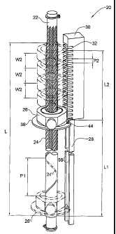
Fig. 2 is a perspective view of a stacking mechanism according to the
present invention.
Fig. 3 is an elevation of the stacking mechanism of Fig. 2 as used in a door
shutter.
Figs. 4A and 4B are a plan view and a sectional elevation respectively of a
traveling nut according to the present invention.
Figs. 5A, 5B and 5C are side elevations of the pivoting mechanism
according to the present invention, in three successive positions.
Figs. 6A, 6B and 6C are side elevations of another embodiment of the
pivoting mechanism, in three successive positions.
CA 02554990 2006-07-31
WO 2004/070156 PCT/IL2004/000039
-7-
Figs. 7A and 7B are elevations of a bar shutter with the stacking mechanism
according to the present invention, in closed and in opened position,
respectively.
DETAILED DESCRIPTION OF THE INVENTION
With reference to Figs. 1A, 1B and 1C, there are shown external perspective
views of a garage shutter 10 with the shutter mechanism of the present
invention,
the shutter closing an aperture with height L and width B. The shutter 10
comprises
a plurality of shutter blades 12 with long edges 14 and short edges 16. In a
closed
position of the shutter shown in Fig. IA, the blades 12 lie generally in the
plane of
the aperture with touching or overlapping long edges 14. In an intermediate
1o position shown in Fig. 1B, the blades 12 are pivoted about axes parallel to
the long
edges, providing access for air or light. In an open position of the shutter
shown in
Fig. 1C, the plurality of shutter blades are stacked in a neat stack 18 under
the
upper beam of the shutter. The stack occupies height L2 leaving a free
clearance of
height L2.
The stacking mechanism and the construction of the whole shutter
mechanism are described in greater detail in the following figures. With
reference
to Fig. 2, there is -shown a stacking mechanism 20 comprising a rotary screw
22
with external thread 24, traveling nuts 26 mounted thereon, an arrester 28,
and a
threaded member 30 with internal thread 32.
The screw 22 has length L and its thread 24 is multi-start thread with pitch
P 1 (one turn thereof is shown under number 24').
With reference also to Fig. 4A and 4B, the traveling nut 26 has a body 34
with internal thread 36 of pitch PI matching the external thread 24 and
external
thread 38 with pitch P2, coaxial with the internal thread. The pitch of the
thread PI
is much greater than the pitch P2. The external thread has less than one turn
and is
formed with two notches 40 and 41, leaving a tooth 44 therebetween. The tooth
44
is at the end of the thread 3 8 turn. The nut body 34 also has a cylinder part
46 with
an annular channel 48. A connection element formed as a ring 50 with an inward
run 52 is mounted on the nut body 34, the rim engaging the channel 48 so that
the
CA 02554990 2006-07-31
WO 2004/070156 PCT/IL2004/000039
-B-
ring can rotate freely about the nut body but can not be displaced axially.
The
connection element has a radial pin 54 externally attached to the ring 50
which is a
part of an articulate joint with the shutter blades 12.
The arrester 28 is an elongated member with C-like cross-section, of length
L1 disposed parallel to the screw. The sides 56 of the C-section engage the
notches
40 and 41 of the nut 26, as shown in Fig. 4A.
The treaded member 30 is formed as a tooth rack parallel to the screw 22,
the teeth constituting the internal thread 32 with pitch P2, matching the
thread 38
on the nut 26. The member 32 has length L2 and is disposed adjacent the
arrester
io 28.
The stacking mechanism 20 operates as follows. With initial position of the
traveling nut 26' within the length L l of the screw, the screw 22 starts
uniform
rotation in one direction. Within the length L1, the traveling nut 26 is
engaged with
the arrester 28 by means of the tooth 44 and notches 40 and 41 which prevents
the
rotation of the nut. Therefore, the nut slides along the screw 22 at rate 11=
P 1 per 1
turn of the screw. When the traveling nut 26 reaches the end of the arrester
28 at
the boundary between lengths L l and L2, the tooth 44 disengages from the
arrester
28. At the same time, the tooth 44 abuts the start of the thread in the
threaded
member 30 which stops the sliding of the nut along the screw 22. But now the
nut
26 is able to rotate together with the screw 22, the tooth 44 and the whole
thread 3 8
following the internal thread 32. Therefore, when within the length L2, the
nut
performs a complex motion including rotation with the screw 22 but with
angular
sliding, and linear translation at rate P2 per 1 turn of the nut. The linear
travel 12 of
the nut per one turn of the screw is:
12=(P1 xP2)/(P1+P2)
Upon reverse rotation of the screw, the nut travels back from the length L2
to the length L l with smooth transition. It will be readily appreciated that
if two
CA 02554990 2006-07-31
WO 2004/070156 PCT/IL2004/000039
-9-
nuts 26 are positioned initially at a distance W1 on the length L l of the
screw 22,
after both nuts pass over to the length L2, they will be positioned at a
distance W2:
W2 = (W l x P2) / (P1 + P2)
With reference also to Fig. 3, when the stacking mechanism 20 of the
present invention is used with a plurality of N traveling nuts 26 arranged at
uniform
intervals WI within the length L I in a first position of the mechanism, then
by
rotation of the screw, the stacking mechanism will be able to transit
reversibly the
1o N traveling nuts into a second position within the length L2 where the nuts
will be
"compressed" at uniform intervals W2. It will be appreciated that by selecting
the
thread pitches P1 and P2, different coefficient of "compression" W1/W2 may be
achieved.
The stacking mechanism of the present invention is advantageously used in
the shutter mechanism 10 shown externally in Fig. 1. With reference also to
Fig. 3,
the shutter mechanism 10 comprises two identical stacking mechanisms 20 (only
one is shown). The stacking mechanisms 20 are disposed parallel to each other
at
two opposite sides of the access aperture with their threaded members 30
beside the
upper beam of the doorframe. A driving unit 60 is provided for synchronous
rotation of the two screws 22. The screws carry each N traveling nuts 26A,
26B,
etc. in symmetric disposition.
The shutter mechanism 10 further comprises a plurality of N flat rectangular
blades 12 with long edges 14, short edges 16 of width W1, and thickness T <
W2.
The short and long edges of the blades are disposed approximately in one
common
plane (the plane of the aperture) in the first position of the stacking
mechanisms, as
shown by blades 12B and 12C, whereby the access aperture is closed. The blades
are stacked under the upper beam 59, turned perpendicularly to the common
plane,
in the second position of the stacking mechanisms, as shown by blade 12`,
whereby
the access aperture is opened.
CA 02554990 2006-07-31
WO 2004/070156 PCT/IL2004/000039
-10-
With reference also to Fig. 4A and 4B, each traveling nut 26 -has a ring
connection element 50 mounted for free rotation about the nut axis. The ring
50 is
mounted to the short edge 16 of a blade 12 by means of a rotary articulated
joint 62
so that each blade can swivel about a blade axis defined by two joints 62.
With reference also to Figs. 5A, 5B and 5C, the shutter mechanism further
has a pivoting mechanism 70 adapted to swivel each blade away from the common
plane before the traveling nuts 26 connected to the blade start their
transition from
the length L1 to the length L2. The pivoting mechanism 70 comprises:
a) N pivoting levers 72, each one firmly mounted to one short edge 16 of
to each blade, generally in a plane perpendicular to the blade axis. Each
lever 72 has a
roller 74 at its free end 76;
b) A guiding member 78 extending parallel to the screw 22. The guiding
member 78 has a channel profile (C-shaped cross-section) which engages the
roller
of each pivoting lever while the blade is traveling along the screw;
c) A movable suspension (not shown) of the guiding member allowing the
guiding member to be displaced from its initial position transversely to the
screw,
while preserving the parallel orientation and the engagement with the roller;
d) A latch 82 preventing the displacement of the guiding member 78 and
disposed at the lower end of the guiding member;
e) an actuator 84 engaged with the screw 22 and adapted to unlock and lock
the latch 82. The actuator 84 is actually a traveling nut 26T that carries a
finger 85
adapted to engage the latch 82 when moving past the latch.
f) A plurality of N traps 88 (recesses) disposed on the guiding member 78 at
intervals W l. The traps 88 are adapted to catch for a while the free end of
the lever
of each blade when its roller falls into the trap.
The shutter mechanism 10 operates in the following way. In the first
position of the stacking mechanism (Fig. 5C and Fig.3), the blades 12 are in
the
common plane, the travelling nuts are on the length L I of the screw, spaced
at
intervals W1 from each other and engaged in the arrester 28. The levers 72 are
orientated upwards, with rollers 74 in the guiding member 78 which is locked
by
CA 02554990 2006-07-31
WO 2004/070156 PCT/IL2004/000039
-11-
means of the latch 82. When the drive 60 starts to rotate the screws 22, the
blades
12 start moving upwards. The actuator 84 unlocks the latch 82 and in the next
moment the rollers 74 are simultaneously caught by the traps 88. The levers 72
push the guiding member 78 aside and the movable suspension allows the
displacement. Thereby, the levers 72 turn about their caught free ends 76 and
turn
the blades 12 away from the common plane (Fig. 5B). In the following travel of
the
blade, the turning of the levers 72 continue but now the caught free ends 76
pull the
guiding member 78 to its initial position. The actuator 84 disengages from the
latch
82, whereby the guiding member 78 is locked in its initial position. The
levers 72
io therefore quit turning and the rollers 74 are pulled out of the traps. All
blades are
now pivoted perpendicular to the common plane and in the further motion
transit
from the length L 1 to the length L2 and are stacked under the upper beam
spaced at
interval W2.
During the upward motion, the rollers 74 successively fall into next traps 88
but the actuator 84 cannot engage the latch anymore. Therefore, the rollers 74
are
pulled out without turning the levers 72.
It should be appreciated that in the reverse (downward) motion, the
operation proceeds exactly in the reverse order.
The pivoting mechanism may be adapted to swivel each blade away from
the common plane just before its traveling nuts start their transition from
the length
L l to the length L2. A second embodiment of the pivoting mechanism shown in
Figs. 6A, 6B and 6C comprises the same parts as in items (a) and (b) above but
has
a simplified turning arrangement, consisting of a single curved portion 90 of
the
guiding member 78. This curved portion is configured to catch for a while the
roller
74 of the lever 72 and to allow a transverse motion of the free end 76 when
the
respective blade 12 travels past the curved portion. It will be appreciated
from the
figures, that the pivoting works both ways. In this case, the blades preserve
their
closed position in the common plane all the way before the length L2.
Another application of the stacking mechanism is shown in Figs. 7A and 7B.
3o A bar-shutter mechanism 100 for the opening 102 comprises two stacking
CA 02554990 2006-07-31
WO 2004/070156 PCT/IL2004/000039
-12-
mechanisms 20 disposed parallel to each other at two opposite sides of the
access
aperture with their threaded members 30 at the upper side of the doorframe.
Screws
22, traveling nuts 26, and driving units 60 are similar to those described
above. The
bar-shutter 100 further comprises a plurality of N bars or rods 112 with ends
mounted to the ring connection elements 50 of the traveling nuts 26. Each two
adjacent bars are connected by diagonal slats 114. One end of the slat 114 is
mounted for rotation on a pin 116 fixed to the upper bar, while the other end
is
mounted for rotation on a pin 118 fixed to a sleeve 120 which is slidingly
mounted
on the lower bar.
In the first position (Fig. 7A) of the stacking mechanisms 20, the nuts 26
and the bars 112 are spaced vertically across the access opening 102, in the
range
L l. The diagonal slats 114 span the space between each two bars dividing it
into
small cells and precluding passage of persons. In the second position (Fig.
7E) of
the stacking mechanisms 20, the nuts 26 and the bars 112 are in "compressed"
state
at the upper side of the access opening, in the range L2. The bars 112 are
close to
each other, the sleeves 120 slide away from the pins 116 and the slats 114
acquire
nearly horizontal position. The opening 102 is free for passage.
It would be appreciated that elements which extend between the bars 112
may be of various nature, such as flexible chains, ropes, mesh, textile,
elastic
sheets, etc.
Although a description of specific embodiments has been presented, it is
contemplated that various changes could be made without deviating from the
scope
of the present invention. For example, the present invention could be modified
and
used with gates, windows, awnings, blinds and other kinds of closures where
precise motion and reliable closing is needed. The shutter mechanisms may be
mounted with vertical screws, with horizontal screws and in any orientation of
the
access aperture plane.