Note: Descriptions are shown in the official language in which they were submitted.
CA 02555028 2009-03-19
DEVICE PROVIDING COORDINATED EMISSION OF LIGHT AND VOLATILE
ACTIVE
RELATED APPLICATION
[0001] Blank.
BACKGROUND OF THE INVENTION
Field of the Invention
[0002] Our invention relates to the integrated presentation of ambient
conditions. More
specifically, our invention relates to the controlled and coordinated emission
of light and
volatile active, e.g., a fragrance, into a given area from a single device.
Description of the Related Art
[0003] Because of their wide array of shapes and sizes, as well as the
seemingly limitless
number of available scents, few things are quite as versatile at setting the
ambience in an area
as scented candles. Scented candles are not without drawbacks, however. For
example,
dripping wax can damage furniture and the skin and, in the extreme, an open
flame can lead
to a structure fire.
[0004] To account for the common problems associated with candles, electronic
lighting
devices that have a flickering candle appearance, such as those disclosed in
U.S. Patent Nos.
5,013,972 and 6,066,924, are generally known in the art. In the '972 patent,
two side-by-side
lamps are alternatingly turned on and off at such frequencies that a
flickering is perceived.
CA 02555028 2009-03-19
2
Similarly, the '924 patent discloses circuitry used to control two light bulbs
in close
proximity to each other such that the bulbs flicker. Moreover, the circuitry
and bulbs of the
'924 patent are contained within a container of a size and shape similar to
common flat
candles. While these patents may suggest devices that mimic the visual
aesthetics of a
candle, they fail to provide the scented candle experience, i.e., they fail to
emit fragrance in
addition to light.
[0005] Fragrance dispensers are also generally known. For example, it is known
to emit
fragrance from an aerosol container upon the activation of a trigger by a
user. Also, other
methods utilize the evaporative properties of liquids, or other vaporizable
materials, to cause
vapors with desired properties to be distributed into the ambient air. For
example, U.S.
Patent No. 4,413,779 discloses a glass container containing a fluid into which
two rigid
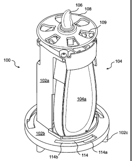
porous nylon wicks extend. The wicks contact a rigid plastic porous element.
In use, the
wicks transport the fluid from the glass container to the ambient air. As a
further example of
air fresheners, the art is also generally aware of atomizer assemblies for
releasing fragrance
from a wick that draws fragrant liquid from a reservoir. For example, commonly
assigned
U.S. Patents Nos. 6,296,196 and 7,017,829 both discussed in detail below,
disclose such
assemblies. Although these representative devices provide fragrance emission,
they do
not provide the visual aesthetic of a candle.
SUMMARY OF THE INVENTION
[0006] Our invention provides a device that emits both light and scent (or
other active
ingredient) similar to a scented candle. More particularly, our invention is
directed to an
improved candle that employs a unique design combining a flameless flickering
effect and an
effective, reliable volatile active delivery system.
[0007] More specifically, in an aspect of our invention, a flameless candle
that releases a
volatile active includes at least one LED, a cartridge mount, and a support
structure. The at
least one LED emits a flickering light that emulates a flame of a candle. The
cartridge mount
receives and secures a replaceable cartridge containing a volatile active to
be released into the
CA 02555028 2006-08-01
WO 2005/074998 PCT/US2005/002984
3
atmosphere over time. The support structure supports the at least one LED and
the cartridge
mount. The support structure is configured to allow airflow across the
replaceable cartridge
when the replaceable cartridge is mounted in the cartridge mount.
[0008] According to another aspect of our invention, a flameless candle
includes at least
one LED, a receptacle, control circuitry, and a housing. The at least one LED
emits a
flickering light that emulates a flame of a candle. The receptacle receives
one or more
batteries that provide power to the at least one LED. The control circuitry
includes at least
one of a current source controller that controls a current supplied to the at
least one LED and
a charge pump that supplies a predetermined forward voltage to the at least
one LED when
the voltage provided by the one or more batteries falls below a predetermined
minimum
voltage. The housing diffuses the flickering light emitted by the at least one
LED. The at
least one LED, the receptacle, and the control circuitry are disposed within
said housing.
[0009] According to a further embodiment of our invention, a flameless candle
for
releasing a volatile active includes at least one LED, a housing, and a mount.
The at least one
LED emits a flickering light that emulates a flame of a candle. The housing
includes a light
diffusing portion. The at least one LED is mounted in the housing such that
the light emitted
therefrom is diffused by the light diffusing portion. The mount is disposed
within housing,
and mounts a replaceable cartridge containing a volatile active. The housing
contains a first
aperture that allows air to enter the housing and flow across the replaceable
cartridge when
the replaceable cartridge is mounted on the mount, and a second aperture that
allows the air
flowing across the replaceable cartridge when the replaceable cartridge is
mounted on the
mount to exit the housing.
[0010] A better understanding of these and other aspects, features, and
advantages of the
invention may be had by reference to the drawings and to the accompanying
description, in
which preferred embodiments of the invention are illustrated and described.
BRIEF DESCRIPTION OF THE DRAWINGS
[0011] Figure 1 is a perspective view of a light and fragrance emitting device
according to
an embodiment of our invention.
CA 02555028 2006-08-01
WO 2005/074998 PCT/US2005/002984
4
[0012] Figure 2 is an exploded view of the device of Figure 1.
[0013] Figure 3 is a side view of the device of Figure 1 with the replaceable
fragrance
cartridge removed and a portion of the chassis cut away.
[0014] Figure 4 is a perspective view of a light and fragrance emitting device
according to
an embodiment of our invention.
[0015] Figure 5 is a sectional view of the device of Figure 4, taken along
section line 5-5 in
Figure 4.
[0016] Figure 6 is a sectional view of the device of Figure 4, taken along
section line 6-6 in
Figure 4.
[0017] Figures 7A-7C are views of a light and fragrance emitting device
according to a
further embodiment of our invention.
[0018] Figure 8 is a perspective view of a light and fragrance emitting device
according to
another aspect of our invention.
[0019] Figure 9 is a perspective view of a light and fragrance emitting device
according to
still another aspect of our invention.
[0020] Figures 10A-10E illustrate further embodiments of a light and fragrance
emitting
device according to our invention.
[0021] Figures 11A-11D illustrate configurations of holders to be used
according to various
aspects of our invention.
[0022] Throughout the figures, like or corresponding reference numerals have
been used for
like or corresponding parts.
CA 02555028 2006-08-01
WO 2005/074998 PCT/US2005/002984
DETAILED DESCRIPTION OF THE PREFERRED EMBODIMENTS
[0023] Our invention provides a device that emits both light and fragrance.
Preferably, our
invention provides a single device that mimics both the visual and olfactory
aesthetics of a
scented candle, without an open flame and with an improved fragrance delivery
system.
[0024] While a preferred embodiment of our invention includes emission of a
fragrance,
and much of the discussion below will be with regard to emission of a
fragrance, we also
contemplate that the dispenser of our invention may alternatively dispense
other volatile
actives. Such alternate volatile actives may include, for example,
disinfectants, sanitizers,
insecticides, insect repellants, medicaments, and such other active
ingredients that are
usefully dispersed into the air. As will be recognized by one of ordinary
skill in the art, other
volatile actives may also be introduced to the ambient environment via
dispensers in much
the same way as fragrances.
[0025] As generally seen in the figures, preferred embodiments of our
invention include a
device for emitting light and fragrance. The device preferably includes an
electrically-
powered light source, a fragrance emitter, a power source, control circuitry,
and a support
structure. All of these components work together to provide a fragrant aroma
and the
appearance of a flickering flame, the flickering effect being provided by the
electrically-
powered light source.
Light Source
[0026] The light source of our invention is an electrically-powered light
emitting device.
While the light source may comprise any number of conventional lighting
devices (including,
for example, incandescent, halogen, fluorescent, etc.), in preferred
arrangements, the light
source comprises one or more light emitting diodes (LEDs). Particularly, as
shown in
Figures 7A-7C, the light source preferably includes two LEDs 252a, 252b.
[0027] An LED emits light of a dominant wavelength, or a very narrow range of
wavelengths. (For purposes of simplicity, although we will refer to the
dominant wavelength
of the LED, that term should be interpreted to include a narrow range of
wavelengths.) For
CA 02555028 2006-08-01
WO 2005/074998 PCT/US2005/002984
6
instance, a blue LED will emit a dominant wavelength of light in the blue
range of the color
spectrum. This dominant wavelength is not substantially controllable for a
given LED
(although the dominant wavelength and intensity can drift slightly with
temperature
fluctuations, for instance). The intensity of the light, however, can be
controlled for a given
LED. For instance, LEDs can be controlled by altering the applied current so
as to vary the
intensity of the light of the LED's dominant wavelength. This can be achieved
by a number
of means; however, pulse width modulation (PWM) is preferred. Preferably, a
controller
receives instructions from a memory or an outside source regarding the
operation of the
LEDs. With PWM, the controller sets a duty cycle for each of the LEDs, thus
defining the
ON times and the OFF times of the LED. During the ON times, i.e., during the
pulse width, a
current is supplied to the LED, and the LED emits light. Accordingly, altering
the pulse
width will alter the amount of time that the LED emits light. Thus, the diode
flickers on and
off as the duty cycle is repeated over time. When this repetition is
accomplished at a
relatively high frequency, the on and off of the diode is imperceptible to an
observer. Thus,
the light will be perceived by the observer to be constantly emitted. When
such is the case, a
flicker effect can be achieved by altering the duty cycles over time to
increase and decrease
the intensity of the emitted light. Alternatively, the flicker effect can be
achieved when the
frequency of the duty cycles is relatively lower, in which case the on and off
times of the
diode are perceptible to the observer, thus providing the flicker. Of course,
combinations of
these flicker methods are also possible. Thus, greater control can be achieved
than in
conventional lights which cannot be turned on and off as rapidly due to the
time it takes to
reach full intensity (e.g., heat the filament in an incandescent bulb) and
cease light emission
(e.g., wait until the filament cools). (It would be recognized by one of
ordinary skill in the art
that, when using pulse width modulation to control one or more LEDs,
substantially constant
intensity lights and flickering lights may both be flickering at a high
frequency imperceptible
to an observer. Thus, flickering and constant intensity light should be
understood herein to
refer to perceived effects.)
[0028] Instead of altering the duty cycles, the controller may alternatively
otherwise adjust
how the current is supplied, thus altering the light emission properties of
the LEDs. For
example, methods utilizing an analog sine wave or a digital potentiometer are
generally
known in the art.
CA 02555028 2006-08-01
WO 2005/074998 PCT/US2005/002984
7
[0029] Consequently, in LED lighting, an observer will observe a color
corresponding to the
dominant wavelength for the LED, and the variation in the pulse width will
have a dimming
effect. This method of controlling LEDs is known in the art, and thus will not
be discussed in
more detail. Other methods of operating LEDs are also known, and the use
thereof would be
obvious to one of ordinary skill in the art.
[0030] When two LEDs are used, as in Figures 7A-7C, the two LEDs 252a, 252b
are
preferably arranged one above the other, i.e., the LED 252a is on a side of
the LED 252b
opposite to a base of the light and fragrance emitting device 200. Preferably,
the upper LED
252a is controlled to emit light at a perceivable intermittence and/or varying
intensity. For
example, the pulse width of the LED may be adjusted over time to vary the
perceived
intensity or to provide perceivable intermittent on and off times for the LED.
Thus, the
flicker may be obtained by providing a constant (perceived) light emission of
varying
intensity, by providing an (perceived) intermittent light emission, or a
combination of the
two. In contrast to the upper LED 252a, the lower LED 252b is controlled such
that light is
perceived to be emitted substantially continuously and/or of a substantially
constant intensity.
This "continuous" light may be the result of a constant current being supplied
to the LED or
by providing a substantially constant pulse width over time, which gives the
observer the
perception of constant light when that LED is viewed on its own.
Alternatively, the pulse
width may be adjusted slightly over time to provide subtle intensity
variations.
[0031] In this fashion, the LEDs 252a, 252b work to create a flicker effect.
For example,
when a conventional candle is lit, the base of the flame appears substantially
steady, while the
portion of the flame further from the base of the wick flickers more
apparently. The present
arrangement of the LEDs 252a, 252b mimics this visual characteristic. It is
preferred that
LEDs having a yellowish or amber hue be used. Specifically, it is preferred
that the LEDs
used have a wavelength of emission in the range of from approximately 580
nanometers to
approximately 600 nanometers, and it is even more preferred that the LEDs used
have a
wavelength of emission in the range of from approximately 585 nanometers to
approximately
595 nanometers.
[0032] Of course, we anticipate modifications to the light source of our
preferred
embodiment. For example, a single LED may be used that is controlled to have a
varying
CA 02555028 2006-08-01
WO 2005/074998 PCT/US2005/002984
8
intensity andlor perceivable intermittence, thereby providing a flickering
effect. A device
using a single LED results in a lower cost apparatus that consumes less power.
Alternatively,
more than two LEDs can be used, perhaps, to create the perception of a larger
flame. Also,
LEDs of many colors are known and could be used, for example, to more closely
resemble a
flame by using hues that are reddish, orangish, and/or yellowish. The colors
can also be
made to change, for example, using RGB LEDs (i.e., an array of red, green,
blue LEDs). By
so varying the types of LEDs used, as well as their arrangement, numerous
aesthetics can be
obtained, including varied colored shows, colored flames, and colored
flickers. And, by
adjusting the duty cycles of the LEDs, the brightness of the light may also be
reduced or
intensified, as dictated by design preference.
[0033] Moreover, when multiple LEDs are used, it is not required that one LED
provide a
light emission of substantially constant intensity while the other LED 252a
provides a flicker
effect. One or both may be held at a substantially constant intensity and one
or both may
emit flickering light.
Fragrance Emitter
[0034] A fragrance emitter is preferably provided integrally with our
invention. The
fragrance emitter preferably includes a replaceable container, having a
fragrance in any one
of a number of conventional forms, including gel and liquid forms. In such gel
and liquid
forms, the fragrance is generally incorporated with a carrier substance, for
example, by
impregnation, intermixture, coating, solubilization, or other means. The
fragrance and carrier
are then contained in a container, for example, a cartridge, a pouch, a
bladder, a reservoir, or
the like, and a portion of the container is formed such that the fragrance can
permeate
therethrough. For example, the fragrance may be emanated through the permeable
portion
when air passes thereover, or the fragrance may be vaporized by the
application of heat and
emanated from the container. In such a case, the dispenser may have a
controllable heating
device to vary the rate at which the volatile is released from the container
or a mechanical
controller for controlling the airflow around the fragrance to be vaporized
(such as a shield or
fan).
. .. .... . .. ~ . . .. .. _ .. . . , .... . ... . . . .
CA 02555028 2009-03-19
9
[0035] Another type of fragrance eniitter is a wick-based emanator, in which a
fragrant
liquid is drawn from a container, such as a reservoir, by a wick, via
capillary action, and
dispersed into the atmosphere. Additionally, the fragrance dispenser may use
an atomizer to
emanate the fragrance from the wick.
[0036] Specifically, this atomizer-type fragrance dispenser uses a wick to
draw a fragrant
liquid from a reservoir. An orifice plate, having minute tapered orifices
therethrough is
disposed in contact with the wick. Connected to the orifice plate is
preferably an actuator
element made of, for example, a piezo-electric ceramic material. The actuator
element is
preferably annularly shaped and the orifice plate is preferably circular.
Electrical power, in
the form of high frequency alternating voltages, is applied to the opposite
upper and lower
sides of the actuator element to produce electrical fields across the actuator
element. These
fields cause the actuator element to expand and contract in radial directions,
causing the
orifice plate to flex, such that a center region thereof vibrates up and down.
As a result of
this vibration, the liquid passes through the orifices of the orifice plate,
and is ejected from
the upper surface of the orifice plate in the form of small droplets.
[0037] A more detailed explanation of this sort of atomization device may be
found in
U.S. Patent No. 7,017,829, which is discussed above. In addition, a more
detailed
explanation of a support structure for the atomizing device may be found in
U.S. Patent No.
6,896,193.
[0038] Of course, other fragrance emitting devices may be substituted as
desired in
consideration of design choices, manufacturing costs, etc. Moreover, even
within each type
of dispenser, variations are possible, as would be appreciated by one of
ordinary skill in the
art.
Power Source
[0039] The power source supplies power to light the light source, and if
required, to the
fragrance emitter to aid in release of fragrance. For example, the power
supply will supply
CA 02555028 2006-08-01
WO 2005/074998 PCT/US2005/002984
voltages to the upper and lower surfaces of the actuator plate in the
atomization-type
fragrance dispenser discussed above. Additionally, the power source may be
used to power
additional components, for example, a fan or a heater.
[0040] In a preferred embodiment, the power source comprises one or more
batteries.
When one battery is used, a voltage step-up or a charge pump (described in
more detail
below) may be used to ensure sufficient power to the components. The batteries
may be
replaceable, or they may be rechargeable. If rechargeable batteries are used,
they may be
removed for recharging, or an adapter may be provided on the device such that
the batteries
can be charged without being removed from the device. For instance, a
receptacle may be
incorporated into the device to receive a plug that supplies power from an
electrical outlet.
[0041] It is not required, however, that the power source comprise batteries.
For example,
power for the device may be derived directly from an electrical outlet. As
will be appreciated
by one of ordinary skill, however, the use of alternate power sources may
require that the
device further include an AC to DC converter.
Control Circuitry
[0042] As used throughout, the term "control circuitry" is intended to be a
representative
term that encompasses all controls that can be used to embody our invention.
For example,
the preferred embodiments are discussed below with reference to
microcontrollers and/or
circuit boards, which all constitute control circuitry. Further contemplated
examples of
control circuitry that may be used to embody our invention are an Application
Specific
Integrated Circuit (ASIC), a microprocessor, and an arrangement of one or more
resistors
and/or capacitors. Control circuitry may or may not include software. These
examples of
control circuitry are not limiting, however. Other control circuitry may also
be used.
[0043] The control circuitry is generally used to control the operation of the
device and is
powered by the batteries. Specifically, the control circuitry is designed to
provide the signals
for controlling the operation of the light source. When one or more LEDs are
provided as the
light source, the microcontroller may alter the duty cycles of the LEDs to
control the
perceived intensity of the emitted light, thereby creating the candle-like
flicker effect.
CA 02555028 2006-08-01
WO 2005/074998 PCT/US2005/002984
11
[0044] When at least two LEDs are used, and one LED receives a constant
current to emit
light perceived to be substantially constant in intensity, that LED can be
controlled separately
from a circuit board, either to receive a power supply from the power source,
when the device
is turned on, or to not receive power, when the device is turned off. In other
words, when one
LED emits constant intensity light, it is not necessary to provide means for
adjusting the
pulse width within a duty cycle thereof (such as the microcontroller). In this
case, the
microcontroller may adjust the operation of only the LEDs that flicker. In
other
embodiments, the constant emission LED may be controlled by pulse width
modulation set
by the controller such that the frequency of the pulse width is imperceptible
to an observer.
In this manner, the intensity of the constant emission LED may be varied
slightly to add to
the overall flicker presentation.
[0045] Also, when a fragrance dispenser including an atomizer is used, the
control circuitry
may include circuits for converting power from the batteries to the high-
frequency alternating
voltages required to expand and to contract the actuator member, thereby
emitting fragrance
from the fragrance dispenser. In addition, the microcontroller may control a
fan, a heating
element, or the like, to aid in dispersion of the fragrance. Furthermore, the
microcontroller
may include controls for automatically turning on and or off one or both of
the light source
and the fragrance dispenser. For example, a timer may be included, and upon a
predetermined elapsed time, some or all of the components will shut off.
[0046] The control circuitry may also serve other functions. For example, when
batteries
are used as the power source, it may be desirable to incorporate a charge
pump. As is
understood, LEDs require a forward voltage to operate. While this forward
voltage may vary
depending on, for example, the color of the light emitted by the LED, the
preferred LEDs
used with our invention may require anywhere from approximately 1.8 volts to
approximately 2.5 volts as a forward voltage, but typically require in the
range of from
approximately 2.0 to approximately 2.1 volts. The charge pump ensures that a
supply voltage
to the LEDs exceeds the forward voltage of the LEDs, when the voltage supplied
by the
batteries lessens, over time, to a voltage below the forward voltage. The
charge pump uses
one or more capacitors to store power in order to generate a voltage level
greater than that
supplied by the battery. Thus, the charge pump can boost the voltage level to
greater than the
forward voltage. In this manner, the LEDs will continue to operate, even
though the batteries
CA 02555028 2006-08-01
WO 2005/074998 PCT/US2005/002984
12
are depleted to a point at which they are outputting a lower voltage.
Consequently, a single
set of batteries can power the device for a longer period of time than if no
charge pump was
used.
[0047] In addition, the control circuitry may incorporate a constant current
source, which
ensures that a constant current is applied to the LEDs, regardless of the
battery voltage.
Otherwise, a higher voltage and corresponding LED current would be supplied at
the
beginning of the battery's life, which would trail off as the battery is used.
This would lead
to an observer perceiving a brighter flicker when a new set of batteries is
installed, and
having that intensity wither as the battery output decreased to the forward
voltage or below,
at which point the charge pump would activate. Thus, by providing a constant
current source,
the LEDs can emit a light having a constant intensity over time, which
prevents a noticeable
dimming as the batteries begin to lose power. When a charge pump is used,
however, current
is not constantly supplied to the LEDs. Because there must be a time interval
during which
the charge pump charges, the power provided through the charge pump is by its
nature
intermittent. Therefore, a constant current is not supplied to the LEDs, and
thus the constant
current source would not function properly, when a charge pump is operating.
[0048] However, it is possible to supply a constant average current to the
LEDs, via a
constant average current source. In a constant average current source, a
current is supplied
during a portion of a cycle to achieve an average current over the cycle that
would equate to
the constant current that would otherwise be provided. Specifically, where a
constant current
source supplies a constant current to each of the two LEDs, a constant average
current source
supplies (i) a current (typically constant) to the first LED for a portion of
a cycle (the cycle is
set based on preferred design aspects and is not the same as the duty cycle
referred to with
respect to the light intensity modulation of the LEDs), (ii) a current
(typically constant) to the
second LED for another portion of the cycle, and no current to either LED
during a final
portion of the cycle. For instance, when two LEDs are provided, a constant
current source
would supply a constant current of, for example, 15 mA to the first LED and 15
mA to the
second LED when the LEDs are enabled. However, for example, a constant average
current
source supplies 45 mA to the first LED for one-third of a cycle and 45 mA to
the second LED
for another one-third of the cycle, with no current being supplied during the
final one-third of
the cycle. Alternatively, because the voltage may slightly decline over the
two-thirds of the
CA 02555028 2006-08-01
WO 2005/074998 PCT/US2005/002984
13
cycle in which the LEDs are enabled, the LED enabled directly after charging
may appear
slightly more intense than the second LED enabled. Accordingly, an alternative
cycle for
driving the LEDs could consist of, in order, a first one-sixth in which
neither LED is enabled,
a second one-sixth in which the first LED is enabled, a third one-sixth in
which the second
LED is enabled, a fourth on-sixth in which neither LED is enabled, a fifth one-
sixth in which
the second LED is enabled, and a final one-sixth, in which the first LED is
enabled. In this
manner, the first LED is enabled directly after charging half of the time, and
the second LED
is enabled directly after charging the other half of the time. Thus, in both
examples, the
average current supplied to the LEDs is the same as that provided by the
constant current
source; however, in this manner, no current is provided to either LED during a
portion of the
cycle, thus reserving a time gap for the charge pump to operate. Consequently,
when the
charge pump is activated, there is no change in operation since the charge
time is already a
dedicated part of the cycle. As would be understood by one of ordinary skill,
the cycle used
by the average current source should be of a sufficiently high frequency that
the LEDs will be
perceived to be constantly emitting light (or to be emitting a perceived
flicker, as discussed
above).
[0049] Many combinations of one or more of the charge pump, the constant
current source,
and the constant average current source may be used. For example, a constant
current source
may be used until such time that the charge pump is activated, and thereafter
a constant
average current source may be used. For the sake of convenience, the term
current source
controller will be used herein to refer to a mechanism for providing a
constant current or a
constant average current. This may be achieved with a constant current source,
a constant
average current source, or a combination thereof.
[0050] The control circuitry may also include controls to shut the device down
when the
batteries get below a certain voltage. In this way, the device will not
continue to draw power
from batteries that are dying, thus lessening the risk that the batteries will
leak battery acid.
Additionally, the control circuitry may be designed, in conjunction with
sensors and/or
switches to allow only operation of the LEDs when a fragrance emitter is
disposed in the
device.
CA 02555028 2006-08-01
WO 2005/074998 PCT/US2005/002984
14
Support Structure
[0051] Our invention also includes a support structure, provided to support
the light source,
the fragrance emitter, the power source, and the control circuitry, or some
combination
thereof. The term "support structure" is intended to encompass any and all of
a chassis, a
housing, a holder, and a base, as those terms are used in the description of
the preferred
embodiments, as well as similar structures used to support or contain the
features of our
invention.
Preferred Embodiments
[0052] Having generally described the components of our invention above,
discussion will
now be made of preferred embodiments of a light and substance emitting device
according to
our invention. These preferred embodiments include various novel arrangements
of the
above-described components, as well as additional features.
[0053] A first embodiment of our invention will be described with reference to
Figures 1-6.
[0054] According to this preferred embodiment, a chassis 102 is provided. As
illustrated,
the chassis 102 comprises a chassis base 102b, and a chassis column 102a
formed on the
chassis base 102b. The chassis base 102b and chassis column 102a may be formed
integrally, or as separate, attachable pieces. The chassis 102 may also
include additional
components. For example, one or more feet 102c may depend from the chassis
base 102b,
the feet 102c being attachable to the chassis base 102b, or formed integrally
therewith.
Additionally, as shown in Figure 1, one or more slotted apertures, or slots
114, are formed
through the chassis base 102b. As illustrated, the slots 114 are preferably
arced and comprise
a wider portion 114a and a narrower portion 114b. The slots 114 will be
described in more
detail below.
[0055] A fragrance emitter 104, a light-emitting tip 106, a collar 108, two
batteries 110, and
controls 112 are preferably disposed on the chassis 102. The batteries 110 are
preferably
removably detachable from the chassis 102, so they may be replaced and/or
recharged as
necessary. The controls 112 preferably include a printed circuit board 116, a
controller 118
CA 02555028 2006-08-01
WO 2005/074998 PCT/US2005/002984
(e.g., an ASIC, a microcontroller, or the like), and two switches 120, 122,
which act in
conjunction with power supplied from the batteries to operate the device.
[0056] In this embodiment, the fragrance emitter 104 is preferably a
replaceable fragrance
cartridge 104a that is removably securable to a cartridge mount disposed on
the chassis 102.
The fragrance cartridge 104a used in this embodiment is preferably a passive
fragrance
emitter. More specifically, the releasable fragrance is preferably contained
within a gel or
liquid and is emitted into the air over time. Accordingly, fragrance is
emitted as a result of
airflow over the cartridge 104a, and no power is needed to emit the fragrance
into the air. As
discussed above, however, a device such as a fan or heater may also be used in
conjunction
with our device to increase the rate at which fragrance is emitted.
[0057] In this embodiment, as shown in Figure 2, the preferred cartridge 104a
includes a
protrusion 124, through which a substantially U-shaped opening 126 is formed,
and the
chassis column 102a has disposed thereon, or formed integrally therewith, a
post 128, which
serves as the cartridge mount. The opening 126 formed on the cartridge 104a
and the post are
designed such that the post fits within the opening, thereby attaching the
fragrance cartridge
104a to the chassis 102. In this embodiment, the cartridge 104a is introduced
and removed
from the chassis 102 through an aperture formed through the base of chassis
base 102b.
(This opening also allows for airflow around the cartridge 104a to aid in
release of the
fragrance, as will be discussed in more detail below.) Thus, the opening on
the cartridge
104a snappingly engages and disengages the post 128.
[0058] Of course, alternative methods are contemplated for securing/removing
the
fragrance cartridge 104a to/from the chassis 102. For example, the cartridge
104a may be
attached and removed from a side of the chassis 102, in which case the U-
shaped opening
126 may not be necessary. Instead, a circular opening may be sufficient to
receive the post
128 therein. Additionally, the post and opening may not be provided at all.
For example, the
chassis 102 and cartridge 104a may be designed so an interference fit is
formed therebetween
to secure the cartridge 104a to the chassis 102. These examples are given only
by way of
example. Numerous cartridge mounts and cartridge configurations are
contemplated, and
would be known to one of ordinary skill in the art. Our invention contemplates
any means by
CA 02555028 2006-08-01
WO 2005/074998 PCT/US2005/002984
16
which a replaceable fragrance emitter can be removably attached to the
chassis. Preferably,
our invention will involve a mechanism for snappingly engaging and retaining
the cartridge.
[0059] As a further feature of this embodiment, means are also provided for
detecting the
presence of the fragrance emitter 104. For example, the device may be
controlled such that
the LEDs will only emit light when a fragrance emitter 104 is attached. As
shown in
Figure 3, a cartridge detector switch 122 is disposed on the chassis 102. For
example, the
cartridge detector switch 122 is actuatable between a normal position and an
actuated
position, and only when the cartridge detector switch 122 is in the actuated
position will the
LEDs emit light. Thus, in this embodiment, when the fragrance cartridge 104a
is attached to
the chassis 102, a portion of the cartridge 104a will contact, and thus
actuate, the cartridge
detector switch 122. This mechanical switch is provided only by way of
example. One of
ordinary skill in the art would recognize that other types of switches and/or
sensors could
similarly be used to detect the presence of the fragrance cartridge 104a.
[0060] The tip 106 is preferably disposed at the top of the chassis column
102a, and
disposed therein is the light source. Preferably, two LEDs, as discussed
above, are arranged
one above the other within the tip 106. Light emitted from the LEDs is
diffused by, and
transniitted through, the tip 106. In this embodiment, as depicted in Figure
2, the tip 106 is a
separate component of the device, disposed within a bore 130 formed in the top
of the chassis
102. The tip 106 may also be formed integrally with the chassis 102. By making
the tip 106
a separate piece, however, the tip 106 may be replaceable, e.g., with other
differently
constructed, or colored, tips. Also, a separate tip 106 may be formed of a
material other than
that used for the chassis 102. Preferably, the tip 106 may be formed of one or
more of
plastic, glass, wax, and the like. Additionally, the tip 106 may be formed of
a glow-in-the-
dark material or of a material that continues to glow for a time after the
LEDs are shut off.
[0061] In this embodiment, a collar 108 is also preferably disposed at the top
of the chassis
102. The collar 108, while shown as a separate component, may also comprise a
part of the
chassis 102. The collar 108 has an aperture formed axially through the center
thereof, and a
portion of the tip 106 is preferably disposed within the aperture. The collar
108 is preferably
actuatable with respect to the chassis 102. Preferably, a user actuates the
collar 108 from a
home position to turn the LEDs on and off. For example, as shown in Figure 3,
the collar 108
CA 02555028 2006-08-01
WO 2005/074998 PCT/US2005/002984
17
may have one or more tines 132 extending downwardly therefrom, and a lip 134
extends
outwardly from a distal end of each of the tines 132. A spring 136 is disposed
between the
chassis 102 and the collar 108, to bias the collar 108 away from the chassis
102. As shown in
Figure 6, formed in the top of the chassis 102 is a plurality of tine-
receiving bores 138 (one
for each of the tines 132), each bore 138 having a shoulder 140. The tines 132
of the collar
108 are received within the bores 138, and the lip 134 of each of the tines
132 contacts the
shoulder 140, to maintain attachment of the collar 108 to the chassis 102.
Thusly, when the
collar 108 is actuated downwardly against the bias of the spring 136, the
tines 132 slide
downwardly within the bores 138. When pressure on the collar 108 is released,
the bias of
the spring 136 returns the collar 108 to the normal, or rest position. An
on/off switch 120 is
preferably disposed beneath one of the tines 132, such that actuation of the
collar 108 causes
the one of the tines 132 to actuate the on/off switch 120, controlling the
LEDs to turn on and
off.
[0062] The device shown in Figure 1 and described to this point is a unitary
device 100 that
emits both a flickering light and a fragrance. While this device could be used
as a stand-
alone device, it is preferably used with a holder 141, as shown in Figures 4,
5, and 6.
[0063] The preferred holder 141 includes an inner shell 142 and an outer shell
144. The
inner shell 142 is preferably generally cylindrical, with an open bottom and
an aperture 143
formed centrally through a top thereof. When the holder 141 is lowered onto
the unitary
device 100, the tip 106 passes through the aperture 143, and an underside of
the top of the
inner shell 142 contacts the collar 108. In this manner, the holder 141 is
rotatable with
respect to the unitary device, i.e., the unitary device remains stationary
while the inner shell
142 (and the remainder of the holder 141) rotate on the collar 108.
[0064] In addition, one or more protuberances 148 extend radially outwardly
from
extensions 147 depending downwardly from the open bottom end of the inner
shell 142. The
protuberances 148 are sized to pass through the wider portion 114a of the
slots 114 formed in
the chassis base 102b when the holder 141 is placed on the unitary device 100,
but will not
pass through the narrower portion 1 14b of the slots 114. The thickness of the
extensions 147,
however, is less than the width of both the wider portion 114a and the
narrower portion 114b
of the slots 114. Thus, the holder 141 is attachable and removable from the
unitary device
CA 02555028 2006-08-01
WO 2005/074998 PCT/US2005/002984
18
100 only when the protuberances 148 are aligned with the wider portions 114a
of the slots
114. But when the holder 141 is lowered completely onto the unitary device
100, the
protuberances 148 are situated below the chassis base 102b, such that the
extensions 147 are
disposed in the slots 114. The holder 141 can thusly freely rotate with
respect to the unitary
device 100, with the rotation being constrained by the slots 114.
[0065] The outer shell 144 is preferably made of material through which the
light emitted
by the LEDs will pass. For example, the outer shell 144 may be made of glass,
plastic, or
wax. Additionally, the outer shell 144 may diffuse the light emitted by the
LEDs. This
diffusion may be in addition to the diffusion accomplished by the tip 106, or
the tip 106 may
not diffuse the emitted light (or may not be included), and only the outer
shell 144 diffuses
the light. The outer shell 144 may also be made of various colors, and may
have formed
thereon various colors, patterns, designs, and the like, depending upon the
desired aesthetic.
[0066] The inner shell 142 and the outer shell 144 may be formed as a unitary
holder 141,
or they may be individual components that are assembled after manufacturing.
Furthermore,
the holder 141 may also include a base 146. The base may be purely decorative,
or it may be
used as a means for securing the inner shell 142 and the outer shell 144
together. As should
be understood, when the holder 141 is situated on the unitary device 100,
because the top of
the inner shell 142 is in contact with the actuatable collar 108, downward
actuation of the
holder 141 will result in downward actuation of the collar 108, thus turning
the LEDs on and
off, as described above.
[0067] As can also be seen in the figures, when the holder 141 is placed on
the unitary
device 100, the inner shell 142 and the chassis base 102b define a
substantially enclosed
cavity in which the fragrance cartridge 104a, batteries 110, and controls 112
are disposed.
The tip 106 extends upwardly from the substantially enclosed cavity, through
the central
aperture 143 in the inner shell 142. As described above, however, the
preferred fragrance
emitter 106 is a passive release system that requires airflow thereacross to
release the
fragrance into the air. Accordingly, it is necessary to allow for airflow
through the cavity,
across the fragrance cartridge 104a. In the preferred embodiment, this airflow
is achieved
through convection. In particular, apertures are formed through the top and
bottom of the
substantially enclosed cavity. As described above, an aperture through which
the fragrance
CA 02555028 2006-08-01
WO 2005/074998 PCT/US2005/002984
19
cartridge 104a is inserted and removed is formed through the chassis base
102b.
Additionally, as shown in the figures, collar apertures 109 are formed through
the collar 108
to allow passage of air, and venting apertures 150 are formed through the top
of the inner
shell 142. Thus, when a portion of the collar apertures 109 is aligned with a
portion of the
venting apertures 150, a passageway is formed through which air can flow
between the
ambient environment and the substantially enclosed inner cavity. In addition,
as should be
understood, rotating the holder 141 with respect to the unitary device, i.e.,
rotating the holder
141 within the slots 114, controls airflow through the collar apertures 109
and the venting
apertures 150 by exposing more or less of the collar apertures 109 vis a vis
the overlaying
venting apertures 150. With this arrangement, ambient air preferably enters
the device
through the aperture formed through the chassis base 102b, and leaves through
the collar
apertures 109 and venting apertures 150.
[0068] A preferred light and fragrance-emitting device has now been described.
Of course,
modifications to this embodiment are contemplated. For example, providing
differently
patterned apertures, more or fewer apertures, and/or larger or smaller
apertures can alter
airflow through the device. For example, apertures may be provided through the
sides of the
inner shell 142 of the holder, in addition to, or instead of, the venting
apertures 150 provided
on the top of the inner shell 142. Also, the collar apertures and/or the
venting apertures 150
may be made larger or smaller.
[0069] Additionally, while the collar 108 was described as being movable up
and down
with respect to the chassis 102 to turn the LEDs on and off, the collar 108
may alternatively
be rotatable with respect to the chassis 102, to turn the LEDs on and off. Or,
the collar 108
may not be actuatable at all, and switches may be provided on an exterior of
the device to
turn the LEDs on and off. Additional switches may also be provided to control
lighting
characteristics of the device. For example, switches may be provided to switch
between
different light shows, or different color LEDs.
[0070] A second embodiment of our invention will now be described with
reference to
Figures 7A-7C, 8, and 9. This embodiment includes features similar to those
discussed
above with respect to the first embodiment, and descriptions thereof will not
be repeated.
CA 02555028 2006-08-01
WO 2005/074998 PCT/US2005/002984
However, in this embodiment, the fragrance emitter preferably includes an
atomizer, rather
than a passive emanation system.
[0071] In this embodiment, a preferred light and substance emitting device 200
of our
invention includes a chassis 202 comprising a chassis cover 202a and a chassis
base 202b,
which together form a cavity that encases each of two LEDs 252a, 252b, a
fragrance emitter
204, two batteries 210, and a printed circuit board with microcontroller 218.
The LEDs 252a,
252b are connected either directly or indirectly to both of the batteries 210
and the
microcontroller 218. As discussed above, the fragrance emitter 204 of this
embodiment
preferably includes an atomizer assembly 205. The alignment of the fragrance
emitter 204,
the batteries 210, and the microcontroller 218 within the chassis 202 is not
critical, but each
of these components is preferably located below a top surface of the chassis
cover 202a.
Also, the LEDs 252a, 252b are preferably located substantially centrally with
respect to a top
surface of the device, and above the fragrance emitter 204, the batteries 210,
and the
microcontroller 218, i.e., on a side of the fragrance emitter 204, the
batteries 210, and the
microcontroller 218 opposite to the chassis base 202b. At least a portion of
the LEDs 252a,
252b is preferably located above a top surface of the chassis cover 202a. By
placing the
LEDs 252a, 252b above the other components in this manner, the emission of
light is not
impeded by these components, so shadows are substantially prevented, and a
more realistic-
looking flame is created.
[0072] Although the alignmerit of the various features within the chassis 202
is not critical,
the chassis 202 preferably includes a horizontal platform 252 (preferably
disposed on the
chassis base 202b) for aligning the fragrance emitter 204 within the chassis
202. The
platform 252 preferably has a platform aperture 254 therethrough with one or
more cutouts
255 formed on a periphery of the platform aperture 254. Preferably, a
replaceable reservoir
256 for use in the fragrance emitter 204 comprises one or more nubs 258 (one
corresponding
to each of the cutouts 255 formed in the platform 252) formed on the reservoir
256. To insert
the reservoir 256, a portion of the reservoir 256 is passed through the
platform aperture 254
of the platform 252, with the nubs 258 passing through the cutouts 255. Once
the nubs 258
clear the cutouts 255, the reservoir 256 is rotated such that the nubs 258
rest on the upper
surface of the platform 252. Also, the top of the platform 252 supports the
atomizer assembly
205 to which the reservoir mates.
CA 02555028 2006-08-01
WO 2005/074998 PCT/US2005/002984
21
[0073] Further, inner surfaces of the chassis 202 may contain various
protrusions. These
protrusions are preferably provided to aid in properly aligning various
components within the
chassis 202 and/or to protect components within the chassis 202. For example,
a vertical
protrusion 260 (shown in Figure 7C) partitions an area for containing the
fragrance emitter
204 from an area having the microcontroller 218. In this fashion, the
microcontroller 218 is
not accessible when the reservoir 256 is replaced, and, accordingly,
inadvertent damage to, or
accidental contamination of, the microcontroller 218 is averted.
[0074] The chassis cover 202a is designed such that it can be placed on the
chassis base
202b, thus forming a unitary device 200. A protrusion or tip 206 is preferably
disposed
approximately centrally on the chassis cover 202a. The tip 206 extends
generally axially, in a
direction away from the chassis base 202b and forms a cavity in which the LEDs
252a, 252b
are disposed when the chassis cover 202a is placed on the chassis base 202b.
(As discussed
above, the LEDs 252a, 252b are preferably arranged one on top of the other.)
The tip 206 is
substantially conical in shape and is preferably made of a material that
diffuses the light
emitted by the LEDs 252a, 252b. However, it may be desirable to alter the
shape of the
protrusion, when, for example, more than two LEDs are used, or the housing is
relatively
wide. For instance, the tip 206 may be more dome-shaped when a wider tip 206
is used with
a wide device 200 (so as to keep the tip 206 relatively close to the chassis
202).
[0075] The tip 206 is preferably between approximately one-eighth of one inch
(3.2 mm)
and approximately three inches high (76.2 mm) and between approximately one-
eighth of
one inch (3.2 mm) and approximately three inches (76.2 mm) wide. The remainder
of the
device 200 is preferably between about two inches (50.8 mm) and about ten
inches (254 mm)
high and preferably between about one and one-half inches (38.1 mm) and about
six inches
wide (152.4 mm). Thus configured, the device 200 can substantially take on the
size and
shape of various conventional candles, while the tip 206, by encapsulating the
LEDs 252a,
252b, simulates a flame.
[0076] The chassis cover 202a also includes an emission aperture 262
therethrough. When
the chassis cover 202a is placed on the chassis base 202b, the emission
aperture 262 aligns
with the fragrance emitter 204. In particular, the emission aperture 262 is
formed such that a
CA 02555028 2006-08-01
WO 2005/074998 PCT/US2005/002984
22
fragrance dispensed by the fragrance emitter 204 passes through the chassis
cover 202a to the
ambient air, i.e., the chassis cover 202a does not impede the dissemination of
the fragrance
from the fragrance emitter 204.
[0077] The chassis cover 202a is preferably secured to the chassis base 202b,
although such
is not required. For example, as shown in Figure 7A, the chassis cover 202a
may be
removably attached to the chassis base 202b such that access to, for example,
the reservoir
256 and/or the batteries 210, may be gained for replacement purposes. When the
chassis
cover 202a is removably attachable to the chassis base 202b, a locking
mechanism may be
employed. For example, attractive magnets may be situated on the chassis cover
202a and
the chassis base 202b, or the chassis cover 202a may include a feature that is
designed for
compatibility with a mating feature of the chassis base 202b. In this manner,
only specific
covers and bases can be used.
[0078] In another aspect, we contemplate that the chassis base 202b and the
chassis cover
202a, when secured together to form the unitary device 200, may be relatively
movable.
Specifically, when the chassis cover 202a is cylindrical, it may be rotatable
on the chassis
base 202b. For example, the rotation of the chassis cover 202a may turn on and
off the LEDs
252a,252b and/or the fragrance emitter 204.
[0079] As an alternative to the removable chassis cover 202a, when, for
example, a new
scent is desired or the reservoir 256 is empty, the device 200 may include a
hatchway for
purposes of replacing the reservoir 256. Examples of two contemplated
hatchways 264a,
264b are illustrated in Figures 8 and 9, respectively.
[0080] As shown in Figure 8, the hatchway 264a may be located on the side of
the device
200. The hatchway 264a is preferably hinged and is not completely removable
from the
device 200. As shown, the hatchway 264a may be opened to gain access to the
reservoir 256.
The hatchway 264a may also open to allow a user access to the batteries 210.
[0081] Alternatively, the hatchway 264b may be formed on the bottom of the
device 200.
For example, as shown in Figure 9, a substantially circular hatchway 264b is
removable from
the device 200. In this configuration, the reservoir 256 is preferably coupled
to the hatchway
CA 02555028 2006-08-01
WO 2005/074998 PCT/US2005/002984
23
264b. By coupling the reservoir 256 thereto, the hatchway 264b supports the
reservoir 256,
and, when assembled, ensures appropriate positioning of the reservoir 256 with
respect to the
atomizer assembly 205. Specifically, when the atomizer assembly 205 is used,
removal of
the hatchway 264b removes a portion of the reservoir 256 from contact with the
atomizer
assembly 205. The reservoir 256 is then removed from the hatchway 264b, a new
reservoir
256 is coupled to the hatchway 264b, and the hatchway 264b is reattached, with
the reservoir
256 properly aligning with the atomizer assembly 205. When the hatchway 264b
of Figure 9
is used, it may be unnecessary for the horizontal platform 252 to support and
to align the
reservoir 256, as the hatchway 264b will perform these functions. As such, the
horizontal
platform 252 will support the atomizer assembly 205, either directly, or
preferably, with a
support.
[0082] The chassis base 202b may also include one or more apertures 266
through which
user control switches pass. A toggle switches 220, for example, allows a user
to turn on and
off one or more of the fragrance emitter 204 and the LEDs 252a, 252b, and a
slider switch
268 allows a user to adjust the rate at which fragrance is emitted from the
fragrance emitter
204. Alternatively or additionally, switches may also be provided that allow a
user to adjust
the light emission properties of the LEDs 252a, 252b, or to change an emitted
light show.
[0083] Thus, like the first embodiment, the second embodiment provides a
unitary light and
substance emitting device 200 that may be used as a stand-alone device. The
device 200 may
be configured to mimic the size and shape of a conventional candle.
[0084] As should thus be apparent, in each of the preferred embodiments, a
unitary device
100, 200 is provided that emits both a flickering light and a substance, such
as a fragrance, to
the ambient air. As discussed above, the preferred unitary device 100 of the
first embodiment
is preferably used in conjunction with a holder 141. The holder 141 is
discussed in detail
above, but is only an example. The unitary device 100 of the first embodiment
may be used
in conjunction with any number of holders. Similarly, the unitary device 200
of the second
embodiment, much like typical replaceable candles would be placed into
decorative holders,
may be also be used in conjunction with unique holders. As used throughout
this application,
holder is meant to encompass any complete or partial encapsulation that holds,
surrounds, is
placed on, or otherwise encapsulates the unitary device.
CA 02555028 2006-08-01
WO 2005/074998 PCT/US2005/002984
24
[0085] Preferably, at least a portion of the holder used with the unitary
device 100, 200 of
either of the embodiments allows light to be emitted therethrough. Figures 10
and 11A-11D
show some representative alternative holder configurations that can be used in
conjunction
with a light and fragrance emitting device.
[0086] When a fragrance emitter is used, the emitted fragrance should also be
emitted from
the holder, and it is thus preferred that the holder provide ample
ventilation. In particular,
when an atomizer assembly is used, as in the second embodiment, the light and
fragrance
emitting device is preferably arranged in the holder such that the emission
aperture through
which the fragrance is dispensed is between about one inch (25.4 mm) and about
six inches
(152.4 mm) from the top of the holder, and substantially away from the inner
surface of the
holder. More preferably, the emission aperture is between about zero inches
and about five
inches (127.0 mm) from the top of the holder. With such an arrangement,
buildup of
fragrance on the inside of the holder is minimized. Moreover, the holder may
be designed to
aid the flow of the fragrance to the ambient environment. By tapering the
holder such that
the width of the holder narrows nearer the top of the holder, airflow will
increase as it leaves
the holder. Furthermore, we prefer that the holder not impede the emission of
light from the
LEDs. Specifically, the unitary device is preferably arranged in the holder
such that the tip is
between about one-half of one inch (12.7 mm) and about two inches (50.8 mm)
from the
holder. More preferably, the tip is between about one inch (25.4 mm) and about
three inches
(76.2 mm). The holder may also act as a diffuser. Furthermore, we envision
that the holder
could further include, for example, a fan for aiding in further dispersion of
the fragrance
emitted from the fragrance emitter.
[0087] The holder may comprise a single piece into which the device is placed.
Alternatively, as shown in Figures 11A-11D, a holder 241 may also comprise a
holder base
241a and a holder cover 241b. More specifically, the device is contained
within, or
alternatively comprises, the holder base 241a that receives and supports the
holder cover
241b. The holder cover 241b, when supported by the holder base 241a, covers
the tip 206.
That is, light emitted from the housing by the respective illumination devices
also passes
through the holder cover 241b. Alternatively, the housing, e.g. the top 206,
may not diffuse
emitted light, and only the holder cover 241b diffuses emitted light.
CA 02555028 2006-08-01
WO 2005/074998 PCT/US2005/002984
[0088] As a specific example of this embodiment, as shown in Figure 11A, a
holder base
241a containing a unitary device as described above in the preferred
embodiments has a
circumferential lip 241c extending radially outwardly from the holder base
241a. At least a
lower portion 241d of the holder cover 241b is sized so as to engage the lip
241c of the
holder base 241a, thereby resting the holder cover 241b on the holder base
241a. Other
illustrative examples of holders 241 are shown in Figures 11B-11D.
[0089] While we envision that the holder cover 241b may rest on the holder
base 241a, it is
preferable that the holder cover 241b detachably attach to the holder base
241a. For example,
the holder cover 241b may be designed to snap onto the holder base 241a.
Alternatively, the
holder cover 241b and the holder base 241a may be designed such that the
holder cover 241b
is rotated onto the holder base 241a, forming a locking engagement. In this or
any
configuration, the holder cover 241b may be relatively movable when secured to
the holder
base 241a. Specifically, when the holder cover 241b is generally cylindrical,
it may be
rotatable on the holder base 241a to turn the LEDs 252a, 252b and/or the
fragrance emitter
204 on and off. Additionally, the engagement and disengagement of the holder
cover 241b
and the holder base 241a may act to turn the light source and/or substance
emitter on and off.
In this manner, the device would only operate with the holder cover 241b
attached.
Moreover, the holder cover 241b and holder base 241a may be specially
designed, such that
only certain covers 241b can be used with the holder base 241a. For instance,
the holder base
241a may include a reader (not shown) that reads an ID (e.g., an RF tag) of
the holder cover
241b. In this manner, the device will not work unless the holder cover 241b
has an
appropriate ID.
[0090] When using the holder 241 according to this embodiment, we also
envision that the
holder cover 241b could emit a fragrance therefrom. For example, materials
such as
polyolefins are known that may be impregnated or infused with a fragrance. By
forming the
holder cover 241b of such a material, the holder cover 241b will emit a
fragrance over time in
addition to that emitted by the fragrance emitter 204. Alternatively, the
device of this
embodiment could not include the fragrance emitter 204, in which case, only
the holder cover
241b will emit a fragrance. Also, with respect to the second embodiment
described above,
we note that the combination of chassis and base resembles a decorative
candle, in which
CA 02555028 2006-08-01
WO 2005/074998 PCT/US2005/002984
26
case a holder may not be desired. In such a case the base or chassis may be
impregnated with
a fragrance.
[0091] Because the holder cover 241b of this embodiment is removable, access
to the
device is facilitated (for example, to change the batteries) and the holder
cover 241b can be
easily replaced. For example, when the fragrance impregnated in the holder
cover 241b is
completely disseminated, a fresh, new holder cover 241b can easily be
purchased and
attached. Also, a user that has recently redecorated, or that wants to move
the device to
another room, may purchase a holder cover 241b having a certain color or other
aesthetic
feature. Moreover, replacement holder covers 241b may provide different
smells. In other
embodiments, the entire holder (or base) may be replaced.
[0092] While several preferred embodiments have been set forth above, many
different
embodiments may be constructed without departing from the spirit and scope of
our
invention. Our invention is not limited to the specific embodiments described
above. To the
contrary, our invention is intended to cover various modifications and
equivalent
arrangements included within the spirit and scope of our invention as defined
by the claims.
The claims are to be accorded the broadest scope, so as to encompass all such
modifications,
equivalent structures, and functions.
CA 02555028 2006-08-01
WO 2005/074998 PCT/US2005/002984
27
INDUSTRIAL APPLICABILITY
[0093] Our invention provides a device for light and/or fragrance ernission.
The device
provides an overall desired aesthetic ambience in an area, such as a room.