Note: Descriptions are shown in the official language in which they were submitted.
CA 02555077 2006-08-02
WO 2005/077757 PCT/US2005/002728
METHODS AND SYSTEMS FOR OPERATING AIRCRAFT LANDING GEARS
TECHNICAL FIELD
~0001~ The following disclosure relates generally to aircraft landing gear
systems and, more particularly, to methods and systems for retracting aircraft
landing gears.
BACKGROUND
10002 Conventional jet transport aircraft typically include retractable
landing
gears to reduce aerodynamic drag during flight. Such landing gears can
extend downwardly from a wing or fuselage for landing and retract upwardly
into corresponding gear wells for flight. Many aircraft also include at least
some form of gear door that closes over the gear wells when the landing gears
are in the extended position. When closed, these gear well doors can protect
systems within the gear wells from foreign object damage during takeoff and
landirig, and can reduce noise and drag. Throughout the following disclosure,
unless otherwise noted, the term "gear doors" refers to gear well doors that
at
least partially cover gear wells after extension of the corresponding landing
gear.
10003 When a conventional jet transport aircraft begins its takeoff roll, the
gear
doors are typically closed and remain in this position until after liftoff.
Under
current practice, pilots wait until the aircraft has achieved a positive rate
of
climb before initiating landing gear retraction. This usually occurs about
three
seconds after liftoff. Landing gear retraction typically begins with the
opening
of the gear doors to expose the gear wells. Next, the landing gears retract
upwardly into the corresponding gear wells. When the landing gears are fully
retracted, or close to fully retracted, the gear doors begin closing behind
the
landing gears to cover the gear wells for flight.
loooa~ Retracting the landing gears quickly after liftoff can provide a number
of
benefits. One benefit is the reduction in aerodynamic drag and the
CA 02555077 2006-08-02
WO 2005/077757 PCT/US2005/002728
corresponding increase in climb-rate that results from "cleaning up" the
aircraft.
Another benefit is the additional clearance that retracting the landing gear
can
provide between the aircraft and ground obstacles during an obstacle-limited
takeoff.
fooos~ Conventional jet transport aircraft typically have hydraulically driven
landing gear systems. On such aircraft, the demands of the landing gear
system typically determines the size of the hydraulic system. One known
method for increasing the speed of landing gear retraction is to increase the
capacity of the hydraulic system. One downside to this approach, however, is
the increased cost associated with a larger hydraulic system. A further
downside is the reduction in aircraft performance that results from the
increased weight of a larger hydraulic system.
SUMMARY
~ooos~ The present invention is directed generally toward aircraft landing
gear
systems and methods for retracting aircraft landing gears. A method in
accordance with one aspect of the invention is usable for retracting a landing
gear of an aircraft during takeoff. The aircraft can include a landing gear
well
configured to receive the landing gear as the landing gear moves from an
extended position to a retracted position. The aircraft can further include at
least one landing gear door moveable between a closed position and an open
position. In the closed position, the landing gear door can at least partially
cover the landing gear well. In this embodiment, the method for retracting the
landing gear includes receiving a first signal during movement of the aircraft
down a runway for takeoff. The first signal can correspond to at least a first
aspect of motion of the aircraft. In response to receiving the first signal,
movement of the landing gear door from the closed position to the open
position is initiated.
looo~a Another aspect of this method includes receiving a second signal after
the aircraft has lifted off of the runway. The second signal can correspond to
at
least a second aspect of motion of the aircraft different from the first
aspect of
2
CA 02555077 2006-08-02
WO 2005/077757 PCT/US2005/002728
motion. In response to receiving the second signal, movement of the landing
gear from the extended position to the retracted position can be initiated.
loooal In a particular aspect of this method, receiving the first signal
during
movement of the aircraft down the runway can include receiving a signal that
is
automatically generated in response to the aircraft rotating upwardly. In
another aspect of this method, receiving a second signal after the aircraft
has
lifted off of the runway can include receiving a signal associated with a
control
input manually generated by a pilot of the aircraft in response to the
aircraft
achieving a positive rate of climb.
10009 An aircraft system configured in accordance with one aspect of the
invention includes a controller configured to be operably coupled to a landing
gear door and a landing gear of an aircraft. The landing gear can be moveable
between an extended position and a retracted position. The landing gear door
can be moveable between a closed position and an open position. The
controller can be configured to retract the landing gear by a method that
includes receiving a first signal during movement of the aircraft down a
runway
for takeoff. The first signal can correspond to at least a first aspect of
motion
of the aircraft. In response to receiving the first signal, movement of the
landing gear door from the closed position to the opened position is
initiated.
The method can further include receiving a second signal separate from the
first signal after the aircraft has lifted off of the runway. The second
signal can
correspond to at least a second aspect of motion of the aircraft. In response
to
receiving the second signal, movement of the landing gear from the extended
position to the retracted position can be initiated.
BRIEF DESCRIPTION OF THE DRAWINGS
10010 Figure 1 is a bottom front isometric view of an aircraft having a
landing
gear system configured in accordance with an embodiment of the invention.
1001 ja Figure 2 is an enlarged, partially schematic, front cross-sectional
view of
a portion of the aircraft of Figure 1 illustrating aspects of the landing gear
system configured in accordance with an embodiment of the invention.
3
CA 02555077 2006-08-02
WO 2005/077757 PCT/US2005/002728
Iool2~ Figure 3 illustrates a flow diagram of a routine for retracting a
landing
gear in accordance with an embodiment of the invention.
loois~ Figure 4 is a graph that illustrates level-loading of a landing gear
hydraulic system in accordance with an embodiment of the invention.
DETAILED DESCRIPTION
10014 The following disclosure describes methods and systems for retracting
aircraft landing gears. Certain details are set forth in the following
description
and in Figures 1-4 to provide a thorough understanding of various
embodiments of the invention. Other details describing well-known structures
and systems often associated with aircraft and aircraft landing gear systems
are not set forth in the following disclosure to avoid unnecessarily obscuring
the description of the various embodiments of the invention.
IooySI Many of the details, dimensions, angles, and other features shown in
the
Figures are merely illustrative of particular embodiments of the invention.
Accordingly, other embodiments can have other details, dimensions, and
features without departing from the spirit or scope of the present invention.
In
addition, further embodiments of the invention may be practiced without
several of the details described below.
iooisl In the Figures, identical reference numbers identify identical or at
least
generally similar elements. To facilitate the discussion of any particular
element, the most significant digit or digits of any reference number refer to
the
Figure in which that element is first introduced. For example, element 110 is
first introduced and discussed with reference to Figure 1.
looi~a Figure 1 is a bottom front isometric view of an aircraft 100 having a
landing gear system 110 configured in accordance with an embodiment of the
invention. In one aspect of this embodiment, the aircraft 100 includes a wing
104 extending outwardly from a fuselage 102. The landing gear system 110
can include a nose gear 112 extending downwardly from a forward portion of
the fuselage 102, and two or more main gears 120 (identified individually as a
first main gear 120a and a second main gear 120b) extending downwardly
4
CA 02555077 2006-08-02
WO 2005/077757 PCT/US2005/002728
from the wing 104. Each main gear 120 can include a wheel truck 122 pivotally
coupled to a main strut 124. The main strut 124 can be pivotally attached to
the wing 104 and configured to retract inwardly and upwardly into a
corresponding gear well 126. In the illustrated embodiment, the gear well 126
extends across a portion of the underside of the wing 104 and the fuselage
102.
lools~ In another aspect of this embodiment, the aircraft 100 further includes
a
first gear door 128 and a second gear door 129. The first gear door 128 can
be hingeably attached to the fuselage 102 and moveable between a closed
position (as illustrated in Figure 1) and an open position (not shown). In the
closed position, the first gear door 128 covers the portion of the gear well
126
that extends into the fuselage 102. In the open position, the gear well 128
can
receive the retracting main gear 120. The second gear door 129 can be
hingeably attached to the wing 104 and coupled to the main gear 120 so that it
moves in conjunction with the main gear 120.
loois~ When the aircraft 100 begins moving down a runway for takeoff, the
first
gear door 128 ("gear door 128") is closed to protect systems within the
fuselage portion of the gear well 126 from foreign object damage. As
described in greater detail below, however, as the aircraft 100 approaches
liftoff speed and begins to rotate upwardly, the gear door 128 starts to open.
In
this way, the gear door 128 can be fully open, or at least close to fully
open,
after liftoff when the pilot determines that the aircraft 100 has achieved a
positive rate of climb and manually initiates the gear retraction process. By
opening the gear door 128 in advance of the pilot initiating gear retraction,
the
overall time for gear retraction can be significantly reduced. In addition, as
further described in detail below, by dovetailing the door opening and gear
retraction operations together in sequence, the demands on the aircraft
hydraulic system (not shown) can be reduced, thereby enabling use of a lighter
and less expensive hydraulic system.
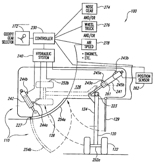
10020 Figure 2 is an enlarged, partially schematic, front cross-sectional view
of
a portion of the aircraft 100 illustrating aspects of the landing gear system
110
configured in accordance with an embodiment of the invention. In one aspect
s
CA 02555077 2006-08-02
WO 2005/077757 PCT/US2005/002728
of this embodiment, the landing gear system 110 includes a hydraulic gear
actuator 241 ("gear actuator 241 ") operably coupled to the main gear 120, and
a hydraulic door actuator 242 ("door actuator 242") operably coupled to the
gear door 128. The gear actuator 241 can include a first hydraulic fluid port
243a ("first fluid port 243a") and a second hydraulic fluid port 243b ("second
fluid port 243b"). The first fluid port 243a and the second fluid port 243b
are
configured to receive pressurized hydraulic fluid from a hydraulic system 240
(shown schematically) for retraction and extension, respectively, of the gear
actuator 241. For example, for retraction of the gear actuator 241,
pressurized
hydraulic fluid flows into the first fluid port 243a from the hydraulic system
240
and drives a piston 261 in a first direction causing it to retract.
Conversely, for
extension of the gear actuator 241, pressurized hydraulic fluid flows into the
second fluid port 243b from the hydraulic system 240 and drives the piston 261
in the opposite direction causing the gear actuator 241 to extend. As the
piston 261 moves in either direction, low pressure hydraulic fluid returns to
the
hydraulic system 240 via the fluid port 243 on the low pressure side of the
piston 261. Retraction of the gear actuator 241 causes the main gear 120 to
pivot upwardly about a trunnion 223 from an extended position 252a to a
retracted position 252b. In the retracted position, the main gear 120 is
neatly
stowed within the gear well 126. Conversely, extension of the gear actuator
241 causes the main gear 120 to return to the extended position 252a.
10021 In another aspect of this embodiment, the gear actuator 241 further
includes a first snubber valve 245a operably coupled to the first fluid port
243a,
and a second snubber valves 245b operably coupled to the second fluid port
243b. The snubber valves 245 can be either mechanically or electrically
actuated to restrict the flow of hydraulic fluid through the respective fluid
ports
243 when the piston 261 approaches either end of its stroke. Restricting the
flow of hydraulic fluid in this manner slows ("snubs") the piston 261 near the
ends of its stroke. Gradually slowing the piston 261 near the end of its
stroke
can prevent damage to the main gear 120 that might otherwise occur if the
main gear 120 is rapidly driven into stops at either the extended position
252a
or the retracted position 252b.
6
CA 02555077 2006-08-02
WO 2005/077757 PCT/US2005/002728
10022 In a further aspect of this embodiment, the landing gear system 110
additionally includes a position sensor 262 (shown schematically) operably
coupled to the gear actuator 241. fn one embodiment, the position sensor 262
can be configured to detect when snubbing of the piston 261 has begun during
retraction of the gear actuator 241. As described in greater detail below,
when
snubbing of the piston 261 begins, the demand placed on the hydraulic system
240 by the gear actuator 241 is gradually reduced. As a result, the hydraulic
system 240 can begin providing power to the door actuator 242 at this point in
time without having to increase its output, i.e., by maintaining a level
hydraulic
load. In one embodiment, the position sensor 262 can include an electrical
device, such as an LVDT (linear variable displacement transducer), to detect
piston snubbing. In other embodiments, other types of devises, such as a
simple mechanically operated switch, can be employed for this purpose.
loo2s~ In yet another aspect of this embodiment, the door actuator 242
includes a first hydraulic fluid port 244a and a second hydraulic fluid port
244b
configured to receive pressurized hydraulic fluid from the hydraulic system
240
for closing and opening, respectively, the gear door 128. For example,
pressurized hydraulic fluid flowing into the first fluid port 244a causes the
door
actuator 242 to retract. Conversely, pressurized hydraulic fluid flowing into
the
second fluid port 244b causes the door actuator 242 to extend. Extension of
the door actuator 242 causes the gear door 128 to open downwardly about a
hinge-line 227 moving from a closed position 254a to an open position 254b.
Conversely, retraction of the door actuator 242 causes the gear door 128 to
move in the opposite direction.
loo2a.~ In a further aspect of this embodiment, the landing gear system 110
additionally includes a controller 230 (shown schematically) operably coupled
to the hydraulic system 240. The controller 230 can be configured to receive
input signals from a number of different sources, and then transmit
corresponding control signals to the hydraulic system 240 for operation of the
main gear 120 and the gear door 128. For example, in one embodiment the
controller 230 can receive manually generated input signals from a cockpit
gear selector 272 (shown schematically). In another embodiment, the
7
CA 02555077 2006-08-02
WO 2005/077757 PCT/US2005/002728
controller 230 can receive automatically generated input signals from a nose
gear sensor 274, a wheel truck sensor 276, and/or an air speed sensor 278 (all
shown schematically).
loo2s~ In yet another aspect of this embodiment, the nose gear sensor 274, the
wheel truck sensor 276, and the air speed sensor 278 have other
arrangements and can be utilized to automatically transmit a signal to the
controller 230 when a particular aspect of aircraft motion indicates that the
aircraft 100 is approaching liftoff during a takeoff roll. For example, the
nose
gear sensor 274 can be configured to automatically transmit a signal to the
controller 230 when the weight on the nose gear 112 (Figure 1) decreases to a
preselected amount. Alternatively, the wheel truck sensor 276 can be
configured to automatically transmit a signal to the controller 230 when the
wheel truck 122 rotates to a preselected angle with respect to the main strut
124. The foregoing signals generated by the nose gear sensor 274 and the
wheel truck sensor 276 can correspond to the aircraft 100 rotating upwardly
during its takeoff roll just before liftoff. In yet another embodiment, the
air
speed sensor 278 can be configured to automatically transmit a signal to the
controller 230 when the aircraft 100 reaches a preselected air speed
corresponding to liftoff In other embodiments, other sensors can be used to
provide other signals corresponding to liftoff. For example, in another
embodiment, a main gear sensor can be included to provide a signal when the
weight on the main gears 120 decreases to a preselected amount.
[0026] AS the aircraft 100 is moving down a runway prior to takeoff, the main
gear 120 is extended and the gear door 128 is closed as shown in Figure 2.
As the aircraft 100 builds up speed, one or more of the sensors 274, 276 or
278 can automatically transmit a signal to the controller 230 when the
aircraft
100 is just about to lift off the runway. As discussed above, in one
embodiment, this signal can be generated by the nose gear sensor 274 when
the weight on the nose gear decreases to a preselected amount. Alternatively,
this signal can be generated by the wheel truck sensor 276 when the angle
between the wheel truck 122 and the main strut 124 reaches a preselected
angle. In yet another embodiment, the signal that the aircraft 100 is just
about
s
CA 02555077 2006-08-02
WO 2005/077757 PCT/US2005/002728
to lift off can be automatically generated by the air speed sensor 278 when
the
air speed of the aircraft 100 reaches liftoff speed. !n other embodiments,
other
signals can be used to indicate that the aircraft 100 is just about to lift
off of the
runway. For example, in one other embodiment, an engine speed signal can
be used for this purpose. In a further embodiment, a weight sensor coupled to
one or both of the main gears 120 can be used for this purpose. In yet another
embodiment, an inclinometer mounted to the airframe can be used.
Accordingly, in still further embodiments, other signals can be transmitted to
the controller 230 when the aircraft 100 is at or near the point of lifting
off of the
runway.
1002~~ When the controller 230 receives the signal indicating that the
aircraft
100 is just about to lift off, the controller 230 sends a corresponding
control
signal to the hydraulic system 240 instructing the hydraulic system 240 to
initiate opening of the gear door 128. The hydraulic system 240 responds by
extending the door actuator 242 causing the gear door 128 to open.
Accordingly, the gear door 128 opens just before or during liftoff of the
aircraft
100, and before the pilot (not shown) has manually initiated landing gear
retraction by operating the cockpit gear selector 272.
loo2s~ Once the pilot has determined that the aircraft 100 has achieved a
positive rate of climb, the pilot initiates landing gear retraction by manual
operation of the cockpit gear selector 272. This event typically occurs two to
three seconds after the aircraft 100 has lifted off of the runway. At this
point in
time, the gear door 128 is fully open, or close to fully open. As a result,
when
the pilot initiates landing gear retraction, the main gear 120 can immediately
begin moving into the gear well 126 without having to wait for the gear door
128 to open.
[0029] AS the main gear 120 approaches the fully retracted position 252b, the
first snubber valve 245a gradually restricts the flow of hydraulic fluid into
the
first fluid port 243a, thereby slowing retraction of the first actuator 241.
In a
further aspect of this embodiment, the position sensor 262 detects the start
of
actuator snubbing and transmits a corresponding signal to the controller 230.
In response, the controller 230 transmits a control signal to the hydraulic
9
CA 02555077 2006-08-02
WO 2005/077757 PCT/US2005/002728
system 240 instructing the hydraulic system to initiate movement of the gear
door 128 from the open position 254b to the closed position 254a. The
hydraulic system 240 responds by gradually increasing the flow of hydraulic
fluid to the door actuator 242 causing the door actuator 242 to retract. In
one
embodiment, this motion can be accomplished by a separate door control
valve, or by an "easy-on" snubbing valve within the door actuator 242. By
gradually increasing the flow of hydraulic fluid to the door actuator 242 at
the
same rate as the flow of hydraulic fluid to the gear actuator 241 is
decreasing,
the demand on the hydraulic system 240 is maintained at an at least
approximately constant level (i.e., the hydraulic system 240 is "level-
loaded").
Once the main gear 120 is fully retracted, the gear door 128 closes behind it.
~0030~ One feature of aspects of the invention described above with reference
to Figure 2 is that opening of the gear door 128 is automatically initiated
before
the pilot initiates retraction of the main gear 120. One advantage of this
feature is that the main gear 120 can begin retracting immediately, or almost
immediately, after the pilot initiates main gear retraction. In contrast,
conventional landing gear systems are configured to respond to the pilot's
gear
retraction command by first opening the gear door 128, and then retracting the
main gear 120. As a result, conventional landing gear systems take
significantly longer to retract the main gear 120 than the landing gear system
110 described above with reference to Figure 2. A further feature of aspects
of
the invention described above with reference to Figure 2 is that the load on
the
hydraulic system 240 can be maintained at an at feast approximately constant
level during retraction of the main gear 120. This "level-loading" is achieved
by
gradually increasing the flow of hydraulic fluid to the door actuator 242 for
door
closure as the flow of hydraulic fluid to the gear actuator 241 for gear
retraction
is decreasing. One advantage of this feature is that the hydraulic system does
not have to be sized to provide full power to both the door actuator 242 and
the
gear actuator 241 at the same time.
loosl~ Figure 3 illustrates a flow diagram of a routine 300 for retracting an
aircraft landing gear in accordance with an embodiment of the invention. In
one aspect of this embodiment, the controller 230 of Figure 2 can include a
io
CA 02555077 2006-08-02
WO 2005/077757 PCT/US2005/002728
computer processor that implements the routine 300 in accordance with
instructions stored on a computer-readable medium. In other embodiments,
the routine 300 can be implemented by other aircraft systems using other
media. The routine 300 starts when the aircraft (not shown) begins moving
down the runway for takeoff with the landing gear down and the corresponding
gear door closed. In block 302, the routine 300 receives a signal indicating
that
the aircraft has begun upward rotation for liftoff. As discussed above with
reference to Figure 2, this signal can be automatically generated when the
load
on the nose gear decreases to a preselected level, when the wheel truck
reaches a preselected angle relative to the main gear strut, andlor when the
air
speed of the aircraft reaches a preselected speed. In block 304, the routine
300 initiates opening of the gear door in response to receiving the signal in
block 302.
[0032] In decision block 306, the routine 300 determines if it has received a
signal from the pilot to retract the landing gear. In one embodiment, as
discussed above, this signal can come from the pilot via actuation of a
cockpit
gear selector. If the routine 300 has not received a signal to retract the
landing
gear, then the routine waits until such a signal is received. When the routine
300 does receive a signal to retract the landing gear, the routine proceeds to
decision block 312 to determine if the gear door is at least X% open. In one
aspect of this embodiment, X can correspond to that percentage of door
movement at which the gear door is sufficiently open such that the landing
gear
can be safely retracted without striking the gear door. For example, in one
embodiment, X% may need to be at least approximately 75% before initiating
landing gear retraction. In other embodiments, the percentage of door opening
can vary depending on the particular landing gear configuration. If, in
decision
block 312, the gear door is not at least X% open, then the routine 300 repeats
until the gear door is at least X% open. Once the gear door is at least X%
open, the routine proceeds to block 314 and initiates retraction of the
landing
gear.
looss~ After initiating landing gear retraction, the routine 300 proceeds to
decision block 316 and waits for the landing gear to be retracted at least Y%.
m
CA 02555077 2006-08-02
WO 2005/077757 PCT/US2005/002728
In one embodiment, Y% corresponds to that percentage of landing gear
retraction at which snubbing of the landing gear motion begins. As discussed
above with reference to Figure 2, the onset of landing gear snubbing can be
detected with a mechanical or electromechanical position sensor operably
coupled to the landing gear actuator. In one embodiment, Y% can be at least
approximately 90%. In other embodiments, landing gear snubbing can occur
at different percentages of landing gear motion depending on the particular
landing gear configuration. If the landing gear is not at least Y% retracted,
then
the routine 300 repeats until the landing gear is at least approximately Y%
retracted. Once the landing gear has been retracted to the point at which
snubbing begins, the routine 300 proceeds to block 318 and initiates closure
of
the gear door. As discussed above, in one embodiment, hydraulic power to the
gear door actuator is gradually increased as hydraulic power to the landing
gear actuator is gradually decreased. After block 318, the routine 300 is
complete.
loos4~ Although one or more of the routines described above initiate opening
of
the landing gear door while the aircraft is still on the runway, in other
embodiments, initiation of landing gear door opening can begin after the
aircraft has lifted off the runway. For example, in one embodiment, a signal
for
gear door opening can be automatically generated when there is no weight on
the landing gear, or shortly thereafter, indicating that the aircraft has just
lifted-
off. In other embodiments, other types of signals can be automatically or
manually generated to initiate gear door opening after the aircraft has lifted-
off
the runway. These signals can be generated in a different manner than the
signal received to initiate landing gear retraction.
loos5l Figure 4 is a graph 400 illustrating level-loading of a landing gear
hydraulic system in accordance with an embodiment of the invention. The
graph 400 includes a vertical axis 402 measuring hydraulic system flow, and a
horizontal axis 404 measuring time. In one embodiment, the events illustrated
by the graph 400 can correspond to the different landing gear retraction
events
described above with reference to Figures 1-3. For purposes of illustration,
opening of the gear door begins with aircraft rotation at Time=Tp. From this
i2
CA 02555077 2006-08-02
WO 2005/077757 PCT/US2005/002728
point, hydraulic system flow increases rapidly from L=0 to level L=1. The
hydraulic system flow maintains this level until the gear door is at least
approximately fully open, at which time the flow to the gear door actuator
decreases rapidly to at least approximately L=0.
loos6~ In the illustrated embodiment, the pilot initiates retraction of the
landing
gear at TG, which is about the same time the gear door is fully opened. As
mentioned above, the pilot typically initiates gear retraction after the
aircraft
achieves a positive rate of climb. While this can occur at about the same time
the gear door is fully open (as illustrated in Figure 4), in other
embodiments,
the pilot can initiate landing gear retraction at other times, such as after
the
gear door is fully open or slightly before the gear door is fully open. When
the
pilot initiates landing gear retraction, the hydraulic flow increases rapidly
back
up to the level L=1. The hydraulic system maintains this flow level while the
landing gear is retracting and until snubbing of the landing gear motion
begins
at TS. At TS, hydraulic flow to the landing gear actuator for landing gear
retraction begins to decrease. At the same time, hydraulic flow to the gear
door actuator for closure of the gear door begins to increase. In this manner,
the load on the hydraulic system is maintained at an at least approximately
constant level. When the hydraulic flow to the landing gear actuator has
stopped, the hydraulic flow to the gear door actuator is at the level L=1 and
maintains this level until snubbing of the gear door actuator begins, at which
time hydraulic flow to the gear door actuator decreases down to the level L=0.
loose From the foregoing, it will be appreciated that specific embodiments of
the invention have been described herein for purposes of illustration, but
that
various modifications may be made without deviating from the spirit and scope
of the invention. Accordingly, the invention is not limited except as by the
appended claims.
13