Note: Descriptions are shown in the official language in which they were submitted.
CA 02555153 2006-08-03
Premix burner with a swirl generator delimiting a
conical swirl space and having sensor monitoring
Technical field
The invention relates to a premix burner with a swirl
generator which delimits a conical swirl space and
provides at least two conical part shells which are
arranged, offset to one another, along a burner axis,
mutually enclose in each case air inlet slits running
longitudinally with respect to the burner axis and have
in combination a conically widening premix burner outer
contour having a maximum outside diameter which narrows
axially into a region with a minimum outside diameter.
Prior art
Premix burners of the generic type mentioned above are
known from a multiplicity of publications with prior
priority dates, such as, for example, from EP Al 0 210
462 and EP Bl 0 321 809, to name only a few. Premix
burners of this type are based on a general operative
principle whereby, within a mostly conically designed
swirl generator which provides at least two conical
part shells assembled with a corresponding mutual
overlap, a swirl flow is generated which consists of a
fuel/air mixture and which is ignited within a
combustion chamber following the premix burner in the
flow direction, so as to form a premix flame which is
as stable as possible in spatial terms.
Whether in a single or a multiple arrangement, premix
burners of this type are used preferably for the firing
of combustion chambers in order to operate a thermal
engine, in particular in gas or steam turbine plants,
especially since these premix burners make it possible
to use different fuels for forming a largely
homogeneous fuel/air mixture which can ultimately be
CA 02555153 2006-08-03
2 -
ignited so as to form an aerodynamically stabilized
premix flame.
The operation of thermal power plants, in particular of
gas turbine plants, has to satisfy high requirements in
terms of their environmental compatibility, while the
exhaust gases released into the atmosphere as a result
of the combustion process are subject to strict
emission limit values. Moreover, thermal power plants
are to be optimized from the standpoint of their
efficiency with which they are capable of converting
energy into electrical energy, this applying as far as
possible over the entire spectrum of their power range.
Present gas turbine plants are operated in a way known
per se according to a permanently predetermined
operating pattern which depends on a limited number of
individually predetermined ambient conditions. Thus,
such ambient conditions are, for example, the ambient
temperature, the air humidity and also fuel qualities,
to name only a few. The operating behavior of a gas
turbine plant is influenced appreciably by these
external influences. Thus, taking into account these
and other ambient conditions, before the gas turbine
plant, for example a predetermined construction series,
is commissioned, what is known as an operating manual
or "operating schedule" is drawn up, according to which
important controlled variables are fixed which are to
ensure as optimized an operation of the gas turbine
plant as possible over the entire load range. The
controlled variables relate particularly to
quantitative and qualitative variables which regulate
the supply of fuel and of combustion air to the burner
unit.
Problems may arise, however, insofar as even the
slightest manufacturing deviations are to be observed
within a gas turbine series which relate particularly
CA 02555153 2006-08-03
- 3 -
to the burner component. Since the premix burner of the
type initially mentioned which is used in the burner
has an optimized form of construction in terms of flame
stability and emission behavior, even the slightest
deviations in the premix burner design which impair the
aerodynamic flow may have considerably adverse effects
on the combustion result. If the combustion process is
conducted in a way known per se by means of permanently
predetermined controlled variables which cannot take
into account the design deviations possibly occurring
as a consequence of manufacture, this leads unavoidably
to an unsatisfactory combustion result, which is
ultimately reflected in the occurence of overheatings
in the burner or in the hot gas path lying downstream
of the burner, in thermoacoustic oscillations, as they
are known, and in impaired emission values. System-
related aging phenomena in the individual components of
the gas turbines also contribute to impairing the
operating behavior of the overall gas turbine plant as
the age of the plant increases.
The aim, therefore, should be to monitor the overall
combustion process actively and to adapt the controlled
variables, such as fuel supply and air supply, which
influence the combustion process to the changes
possibly occurring at that particular time. However,
this presupposes a multiplicity of sensors detecting
the operating behavior of the burner, with the result
that the burner arrangement becomes arbitrarily
complicated and ultimately cost-intensive in terms of
production, although it is expedient to detect burner
operating variables, such as fuel and air supply, flame
temperature, the occurrence of thermoacoustic
oscillations and surface temperatures, in order to
obtain as complete a picture as possible of the current
burner situation.
CA 02555153 2011-11-08
-4-
Summary
The object on which the invention is based is to develop a
premix burner with a swirl generator which delimits a conical
swirl space and provides at least two conical part shells
which are arranged, offset to one another, along a burner
axis, mutually enclose in each case air inlet slits running
longitudinally with respect to the burner axis and have in
combination a conically widening premix burner outer contour
having a maximum outside diameter which narrows axially into a
region with a minimum outside diameter, in such a way that the
integration of differently designed sensor units into the
housing of the premix burner is possible at as low an outlay
as possible in structural terms. In particular, it is
expedient to take measures on the premix burner whereby an
adaption of the most diverse possible sensor units can be
implemented easily and without a high outlay in servicing
terms. The measures to be taken should likewise be capable of
being carried out on premix burners which are already in use,
so that there is the possibility of the retrofitability of
suitably designed sensor units on premix burners which are in
operation.
The solution for achieving the object on which the invention
is based is described herein. Features advantageously
developing the idea of the invention may be gathered from the
further description, particularly with reference to the
exemplary embodiments.
According to the invention, a premix burner with a swirl
generator which delimits a conical swirl space is designed in
such a way that at least one conical part shell provides, in
the region between the maximum and the minimum outside
diameter, a reception unit which deviates from the
CA 02555153 2006-08-03
-
conically widening premix burner outer contour and
locally elevates the premix burner outer contour
radially outward and which has a maximum radial extent
which is dimensioned smaller than half the maximum
5 outside diameter of the premix burner outer contour.
This requirement arises from the desire for as compact
a form of construction as possible, without the radial
installation width of a premix burner in this case
being impaired. Thus, in many instances, premix burners
have in the axial direction a corresponding connection
flange to a combustion chamber, at least the premix
burner being surrounded by a housing enclosing a flow
space in which the premix burner is supplied with
incoming air. For maintenance reasons, the housing
mostly has a correspondingly closable mounting orifice
through which the premix burner can be mounted onto the
combustion chamber housing axially. Owing to its
compact external shape, the reception unit designed
according to the invention in no way impairs the axial
mountability of the premix burner and, moreover, offers
the implementation of a sensor unit. For this purpose,
the reception unit has at least one hollow duct with at
least one duct orifice which faces away from the swirl
space and via which the sensor unit can be implemented
in the reception unit, the hollow duct having a duct
longitudinal extent which runs essentially parallel to
the burner axis. The duct longitudinal extent directed
parallel to the burner axis allows the implementation
of corresponding sensor units coaxially to the burner
axis, with the result that even a premix burner
equipped with corresponding sensor units has no
components, the maximum radial extent of which projects
beyond the maximum outside diameter of the premix
burner housing, so that, even in this case, an axial
mountability of the overall premix burner is
maintained.
CA 02555153 2006-08-03
- 6 -
The particular features of the premix burner
arrangement according to the invention are further
dealt with in detail with reference to the exemplary
embodiments.
Brief description of the invention
The invention is described below by way of example,
without the general idea of the invention being
restricted, by means of exemplary embodiments, with
reference to the drawings in which:
fig. 1 shows a diagrammatic illustration of a
longitudinal section through a premix
burner,
fig. 2 shows a cross-sectional illustration
through a premix burner, and
fig. 3a to 3d show a longitudinal section in each
case through a reception unit designed
according to the invention, with
different hollow ducts for the
reception of different sensor units.
Way of implementing the invention, commercial
applicability
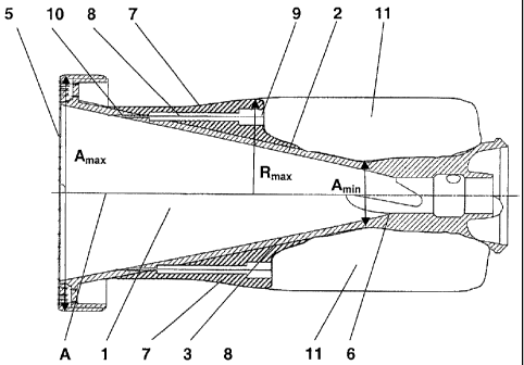
Fig. 1 illustrates a longitudinal sectional
illustration through a premix burner designed according
to the invention, which has a conically designed swirl
space 1 delimited by two conical part shells 2, 3. The
conical part shells 2, 3 are arranged so as to be
offset with respect to a burner axis A (see in this
case the cross-sectional illustration according to
fig. 2) and mutually enclose in each case air inlet
slits 4. Furthermore, the two conical part shells 2, 3
have a premix burner outer contour which at the
CA 02555153 2006-08-03
- 7 -
location of the burner outlet 5 has a maximum outside
diameter Amax which narrows axially and provides a
region 6 with a minimum outside diameter Amin in which a
central burner nozzle arrangement (not illustrated) can
usually be positioned. In the exemplary embodiment
illustrated in fig. 1 and 2, a reception unit 7 is
provided in each case for each conical part shell 2, 3
and is joined firmly to the outer wall of the
respective conical part shells 2, 3. The reception unit
7 has a maximum radial extent Rmax which is smaller or
markedly smaller than half the maximum outside diameter
Amax. This ensures that the premix burner unit can be
lead, unimpeded, axially through mounting orifices
which have only an insignificantly larger mounting
diameter than the maximum outside diameter Amax. The
reception unit 7 according to the exemplary embodiment
in fig. 1 and 2 is designed as a separate component
which can be joined in the form of a retrofit kit to
the outer wall of the respective conical part shell 2,
3. It is, of course, possible to connect the reception
unit 7 in one piece to the conical part shell during
the production of the latter.
For the purpose of mechanical stabilization and also
for protection against damage due to mounting work,
supporting flanks 11 are attached to the outer housing
of the premix burner and likewise do not project beyond
the maximum outside diameter Amax-
To implement a suitably designed sensor unit, the
reception unit 7 has at least one hollow duct 8, the
duct longitudinal extent of which is oriented parallel
to the burner axis A. The hollow duct 8 has, moreover,
in the exemplary embodiment illustrated in fig. 1, a
first duct orifice 9 which is open axially outward and
allows the possibility of an axially directed push-in
of a correspondingly designed sensor unit adapted in
bar form to the inner contour of the hollow duct 8.
CA 02555153 2006-08-03
- 8 -
Depending on the type of sensor unit, the inner contour
of the hollow duct 8 may be designed in any desired
way. In the exemplary embodiment illustrated, the
hollow duct 8 issues directly into the swirl space 1
via a second duct orifice 10. With further reference to
the exemplary embodiments according to fig. 3, it
becomes clear that the hollow duct 8 may have different
inner contours, depending on the type of sensor used.
What is common to all the hollow duct designs, however,
is that they have an orientation which is coparallel to
the burner axis A and allows axially directed equipping
with corresponding sensor units.
As already mentioned, fig. 2 shows a cross-sectional
illustration through the premix burner illustrated in
fig. 1. It may be gathered from the cross-sectional
illustration that the reception unit 7 has passing
through it not only the hollow duct 8 designed as a
main duct, but also in each case two further hollow
ducts 8' into which corresponding sensor units can
likewise be introduced. Moreover, it is particularly
advantageous to arrange the reception unit 7 as
centrally as possible, on the top side, facing away
from the swirl space 1, of the conical part shell 2, 3,
between the fuel supply pipe 19 and the shell end edge
20 in the circumferential direction, in order as far as
possible not to influence the air stream directed into
the air inlet slits 4. It has proved particularly
advantageous to select the distance between the
reception unit 7 and the shell end edge 20 exactly
double the maximum radial elevation of the reception
unit 7 above the top side of the conical part shell. Of
course, furthermore, the surface contour of the
reception unit 7 should have as streamlined a
configuration as possible.
The longitudinal sectional illustration according to
fig. 3a to d show alternative embodiments of
CA 02555153 2006-08-03
- 9 -
differently designed hollow ducts which are adapted in
each case for different sensor types.
Fig. 3a has a hollow duct 8 which provides essentially
two duct portions 12 and 12' having differently
dimensioned diameters, the duct portion 12 of larger
cross-sectional dimensioning being suitable preferably
for the use of a microphone sensor 13. The duct portion
12 issues directly, via a duct portion 12' dimensioned
with a smaller diameter, into the swirl space 1, by
which, for example, pressure fluctuations can be
transmitted, such as are initiated in the inner space
of the combustion chamber due to the formation of
thermoacoustic oscillations. In addition, the reception
unit 7 provides a scavenging duct 14 via which cooling
air can be fed into the hollow duct 8 in order to avoid
the overheating of the microphone sensor unit 13. If
cooling air is introduced under pressure through the
scavenging duct 14 from outside into the hollow duct 8
in the region of the duct portion 12' the cooling air
prevents the ingress of hot gases into the hollow duct
8 through the duct orifice 10 and thereby serves for
preventing the overheating of the sensor unit.
In the exemplary embodiment according to fig. 3b, the
hollow duct 8 is designed with a constant inside
diameter for the introduction of an optical flame
sensor 15. The optical flame sensor 15 has an
observation angle range 16 which is delimited, on the
one hand, by the exit aperture of the optical flame
sensor 15 and, on the other hand, by the duct orifice
10 enlarging the viewing angle. Again, to avoid an
overheating of the flame sensor 15, a scavenging duct
14 serves for the supply of corresponding cooling air.
The scavenging duct 14 is in this case provided in the
immediate vicinity of the duct orifice 10, in order
effectively to protect the front aperture region of the
flame sensor 15 against thermal contact with the hot
CA 02555153 2006-08-03
- 10 -
gases. With the aid of the optical flame sensor 15, the
flame front forming within the combustion chamber can
be monitored, the spatial position of said flame front
being an important indication of stable combustion.
Fig. 3c has a double duct routing 8, 8, the hollow
ducts 8, 8' designed as blind holes running parallel to
the burner axis A. Moreover, both hollow ducts 8, 8'
have duct portions 17, 17' running perpendicularly to
the burner axis, the duct portion 17 issuing into the
swell space 1 and the duct portion 17' issuing into the
atmosphere surrounding the premix burner. With the aid
of the hollow duct design illustrated in fig. 3c, it is
possible to carry out a differential pressure
measurement. The differential pressure measurement
serves essentially for determining the air throughflow
through the burner. Consequently, it is possible to
determine nonuniformities of the air distribution
within the gas turbine housing and/or nonuniformities
of the throughflow characteristic from burner to
burner, insofar as there is a multiple burner
arrangement. If differential pressure measurements are
carried out on a plurality of conical shells of a
burner, the nonuniformity of the air flow within a
single burner can also be determined.
Finally, the exemplary embodiment according to fig. 3d
shows a hollow duct 8 which is designed as a complete
blind hole and into which a thermosensor unit 18 can be
introduced.
Of course, the sensor units described in the above
exemplary embodiments can be combined in any desired
way within a single reception unit 7, so that as high a
multiplicity of different measurement data as possible
can be obtained from the premix burner.
CA 02555153 2006-08-03
- 11 -
Thus, the sum of the above-described sensor units makes
it possible to detect a multiplicity of operating
variables, such as, for example, the flame temperature
or the premix burner temperature within the conical
part shells in order to determine the current load on
the premix burner, so that, if appropriate, if
overheatings are detected, corresponding cooling
measures can be initiated.
It is also possible to carry out differential pressure
measurements along the burner delivery lines, with the
result that controlled monitoring and setting of the
fuel supply, particularly in the case of a staged fuel
supply, become possible. The flame temperature and the
nitrogen oxide emission can thereby be influenced
directly. With the aid of suitably designed optical
sensors, the flame temperature, particularly in the
premix flame forming within the backflow zone, can be
determined. Likewise, the combustion quality can be
monitored and correspondingly determined optically.
With the aid of suitable pressure-sensitive sensors,
such as, for example, microphone sensors, moreover, it
is possible to detect thermoacoustic oscillations or
pulsations which arise. With the aid of the measurement
data obtained in the above way, active readjustment of
the combustion process with a view to as optimized a
combustion as possible can be carried out. With the aid
of the design solution according to the invention,
which, as stated, may also be carried out within the
framework of a retrofit on already existing premix
burners, it is possible to readjust the burner behavior
to burner conditions currently occurring and
influencing the burner'process.
It is particularly advantageous, in the case of a
multiple burner arrangement, to arrange the measurement
sensor units in a plurality of burners. It is thereby
possible to determine local distributions of
CA 02555153 2006-08-03
- 12 -
pulsations, flame temperatures, pressure distributions,
etc., and consequently the local distribution of the
combustion quality can be deduced, so that, ultimately,
the local burner conditions can also be readjusted.
CA 02555153 2006-08-03
- 13 -
List of reference symbols
1 swirl space
2, 3 conical part'shells
4 air inlet slits
burner outlet
6 region with minimum outside diameter
7 reception unit
8 hollow duct
9, 10 duct orifice
11 supporting flank
12, 12' hollow duct portions
13 microphone sensor
14 scavenging duct
optical flame sensor
16 see angle range
17, 17' second duct portion
18 thermosensor
19 fuel supply pipe
shell end edge