Note: Descriptions are shown in the official language in which they were submitted.
CA 02555214 2006-08-03
WO 2005/078502 PCT/US2005/003215
Integrated Panoramic and Forward Optical Device, System and Method for
Omnidirectional Signal Processing
Field of the Invention
This invention relates to the field of omnidirectional optical systems. The
optical system is comprised of
two paths, panoramic and forward, seamlessly integrated on a single plane. The
total field of view is comprised of
the forward field of view and the panoramic field of view.
Backer ound ofthe Invention
There is much prior art for optical systems that provide omnidirectional
imaging. The disclosure herein
has some unique characteristics that are not covered in any prior art and that
provide a unique new capability to
imaging systems and omnidirectional optical components in general. Jeffrey
Charles has several U.S. patents on the
subject including US patent 6,333,826 and US patent 6,449,103, BeHere
Corporation has several US patents
including US 6,392,687, US 6,424,377 and US 6,480,229, and Remote Reality has
US patent 6,611,282.
The patents by Jeffrey Charles focus solely on the panoramic field of view,
and efforts to maximize that
field of view for near field applications. The Charles' patents include a
frontal exclusion zone of about 60 degrees
that can be tapered approaching the far field by the use of a torroidal-shaped
reflector. Although this exclusion
zone eventually disappears as a point where the boundaries of the panoramic
field meet, there is no account in the
patent for the overlapping area past the point of convergence in the
processing or interpretation of the image. The
minor disclosure of including forward optics to image the frontal exclusion
zone makes no mention of details of
how to match the magnification or the relative F/# of the integrated images.
Nor is there a means of interpreting or
processing the overlapping images. The mere inclusion of forward viewing
lenses does not automatically lend itself
to an easily interpretable image. The focus of the optical system is near
field prior to the overlap. Although there is
provision to include the forward viewing optics to image the frontal exclusion
zone, there will only be one point (or
one radial distance) in which the frontal zone and the panoramic zone exist
with either no gap or no overlap.
The BeHere technology also concentrates on the panoramic field of view and
only makes provisions to
extend the panoramic view as far forward as possible by changing the shape of
the reflector. By placing a dimple in
the apex of the parabolic reflector, imaging beyond the secondary reflector is
achieved in the far field. These
inventions provide no means for forward imaging in the near field.
The Remote Reality invention is a super wide-angle panoramic imaging apparatus
that claims up to a 260°
vertical field of view using a two reflector configuration. The invention
includes an undefined blind spot along the
optical axis. The invention claims a single view point while also having a
substantially flat and stigmatic image
plane.
Below are some summarizing details of each of the patents referenced above.
US 6, 333, 826 Jeffrey R. Charles: Omrzirarnic Optical System Having Central
Coverage Means Which Is Associated
With a Camera, Projector or Similar Article
single and two reflector embodiments
two reflector embodiment produces frontal exclusion zone ~ 60 degrees
produces annular image
~ minimization of frontal exclusion zone using torroidal shape primary
reflector
achieves far field imaging with triangular shape frontal exclusion zone,
beyond point, overlap in annular image
CA 02555214 2006-08-03
WO 2005/078502 PCT/US2005/003215
~ discloses in specification only (column 26, line 57 - column 27, line 9) use
of supplemental lenses in front of
secondary mirror transparent area to image area greater than or equal to
frontal exclusion zone, produces
concentric images
~ overlapping images to produce 3D info
~ FOCUS: maximization of annular image boundaries, minimization of frontal
exclusion zone, far field imaging,
overlap of zones to produce 3-D image information
US 6,449,703 Jeff~ey R. Charles: Solid Catadioptric Orrznidirectiorzal Optical
System Having Central Coverage
Means Wlziclz is Associated with a Camera, Projector; Medical Irtstrumerzt or
Similar Article
~ solid optical substrate with primary and secondary internal reflectors and
outer surface being convex refracting
surface
~ combination of primary reflector shape and outer refracting surface allows
for imaging a point a finite distance
in front of said optical system - thereby allowing for far field imaging only -
but also subject to image
overlapping beyond that finite point
~ purpose of the convex refracting surface, which would be extremely difficult
or even impossible to
manufacture, is to extend the panoramic field of view boundaries.
~ Claims 31-36 deal with solid optical substrate with primary and secondary
internal reflectors in which
secondary reflector has a transparent central zone with a concave surface or
lenses to image central exclusion
zone.
US 6,392, 687 BeHere Corp.: Method and Apparatus for Irnplemerztirrg a
Parzoptic Camera System
Two reflector design
~ Main reflector consists of a paraboloid shape with a dimple on the apex such
that the main reflector can capture
light from behind a second reflector
~ Details two cameras together to see an entire sphere and a stereo vision
panoptic camera
~ Similar to Charles' patent, still leaves a zone just beyond secondary
reflector which is not viewable
US 6,424,377 BeHere Corp.: Panoramic Carrzera
~ Single reflector design - mirror is parabolic cone shape
~ Includes imaging camera, astigmatism correction lens, field flattening lens
and objective lens
~ Multiple sensors on same plane in mosaic pattern to achieve desired
resolution
~ Alternative embodiment 2 reflector design - camera housed within parabolic
mirror
~ Alternative embodiment single and 2 reflector designs whereas the parabolic
reflector is the inside surface of a
curved block of transparent material with refractive properties
~ annular image presentation techniques including conversion to rectangular
coordinates
~ claims apparatus for capturing panoramic images
~ claims apparatus with parabolic first reflector and light capture linearly
proportional to angle of incidence on
mirror
US 6,480,229 BeHere Corporation: Panoramic Camera
2
CA 02555214 2006-08-03
WO 2005/078502 PCT/US2005/003215
~ single reflector convex mirror incorporating a beamsplitter to send annular
image to two different electronic
image capture devices
~ Alternative embodiment 2 reflector design - camera housed within parabolic
mirror Alternative embodiment
single and 2 reflector designs whereas the parabolic reflector is the inside
surface of a curved block of
transparent material with refractive properties
~ annular image presentation techniques including conversion to rectangular
coordinates
US 6,611,282 Remote Reality: Super Wide-Angle Parrot°amic Imaging
Apparatus
~ two reflector configuration, primary reflector is a hyperboloid and
secondary reflector is concave
~ achieves up to a 260° vertical field of view which includes an
undefined blind spot along the optical axis
immediately behind the secondary reflector
~ claims image is free of field curvature effects and astigmatic effects
~ secondary reflector is an ellipsoidal or spherical mirror
~ alternative embodiment includes reflective elements housed in solid optical
block
~ image mapable into Cartesian coordinate system
Other prior art which defines the general state of the art but is not of
particular relevance includes: US
6,621,516 to Wasson, et al. for a Panoramic Pipe Inspector; US 6,744,569 to
Geng for a Method and Apparatus for
Onanidirectiohal 3-D Imaging; US 6,789,908 to Garcia for a Confocal
Ellipsoidal Mirror System for Wide Field of
View Imaging; US 6,791,598 to Luken, et al. for Methods arad Apparatus for
Infot°fuation Capture and Stereoscopic
Display of Pafzoramic Images; US 6,793,356 to Kumata, et al. for an
Ornnidirectiot~al Vision Sensor; US 6,809,887
to Gao, et al. for an Apparatus and Method for Acguiring Uniform-Resolution
Panoramic Images; and US
6,833,843 to Mojaver, et al. for a Panoramic Irnagihg and Display System Witla
Caf2onical Magnifier.
Summary of the Invention
The objective ofthe device, system and method for omnidirectional signal
processing disclosed here is to
provide an integrated panoramic / forward view imaging system that delivers a
coplanar omnidirectional image to a
means of image display and/or recording. The present invention is comprised of
a two optical path system that is
combined on a single image plane. This device, system and method achieves
matched magnification between the
forward and panoramic images, relatively seamless boundaries with no overlap
or blind spot, and a total field of
view approximating 270 degrees vertically (forward) about the entire 360-
degree periphery. The invention can be
utilized for surveillance applications as a pole mounted or ground mounted
system or implemented in a stand-alone
unit. The optical system can be miniaturized for endoscope and borescope
implementation or alternatively enlarged
for pipe inspection or other large-scale inspection implementations. An
alternative non-imaging embodiment of the
present invention can be applied to optical free space communication as an
omnidirectional optical antenna.
In particular, disclosed is a device, system and method integrating forward
and panoramic fields,
comprising: a primary reflector, comprising a convex surface in relation to
the forward field, reflective on at least
part of the convex surface; a secondary reflector, forward of the primary
reflector relative to the forward field,
reflective on at least part a surface thereof facing rearward toward the
primary reflector; a primary reflector hole in
the primary reflector, substantially centered about an optical axis of the
apparatus; and a secondary reflector hole in
the secondary reflector, substantially centered about the optical axis.
CA 02555214 2006-08-03
WO 2005/078502 PCT/US2005/003215
Brief Descr~tion of the Drawings
The features of the invention believed to be novel are set forth in the
appended claims. The invention,
however, together with further objects and advantages thereof, may best be
understood by reference to the
following description taken in conjunction with the accompanying drawings)
summarized below.
Figure 1 is a two dimensional plan view of the optical system of a preferred
embodiment of the invention.
Figure 2 is a two dimensional schematic showing the ray trace of the panoramic
component of the optical
system in said preferred embodiment.
Figure 3 is a schematic representation of the fields of view attainable with
the present invention.
Figure 4 illustrates the projection ofthe captured image onto the image plane.
Figure 5 is a two-dimensional schematic of an alternative embodiment of the
present invention as an afocal
optical system for non-imaging applications. The ray traces are similar to
those which occur in imaging
embodiments.
Figure 6 is a two-dimensional schematic of an alternative embodiment
comprising directional zooming
capabilities.
Detailed Description
Purpose ahd Applications
The device, system and method disclosed herein is configured to achieve the
widest field of view possible,
including rear-viewing capabilities, while minimizing distortion. It does not
rely on panning and tilting
mechanisms. Current wide field of view, non-moving, optical systems typically
consist of fish eye optical systems.
The distortion of fish eye optical systems is so great that they are not
suitable for many imaging applications. The
distortion is created by the non-uniform refraction of the light rays across
the field of view. The boundaries of the
field of view typically appear much more distorted than the central area of
the field of view since the geometry of
the optical system is meant to maximize the field of view. Advances in
alternative panoramic imaging optical
systems present a means of imaging the periphery, but typically not the entire
hemisphere in front of the imager.
Single and dual reflector optical systems exist that provide peripheral
imaging, but lack forward imaging. Pan and
tilt optical systems provide the means to cover the same field of view, but
require mechanical motion and do not
present the entire field of view in a single instance on the image plane. For
many applications the lack of constant
viewing of the entire field of view or the requirement of mechanical motion is
unacceptable. This disclosure has
applications including but not limited to surveillance, safety monitoring,
industrial inspection, and medical
endoscopy.
Optical System
The basic configuration disclosed herein is described with reference to
Figures 1 and 2. Figure 1 shows
the layout of the omnidirectional optical system 100 and Figure 2 shows the
light path through this system: The
omnidirectional optical system 100 comprises a primary reflector 102, a
secondary reflector 104, a forward imaging
lens group 106, a focusing lens group 108, an image plane 110, all positioned
as illustrated in relation to an optical
axis 112. The fields of view imaged by the omnidirectional optical system 100
are detailed in Figure 3. The total
field of view of the omnidirectional optical system 100 comprises a forward
field of view 318 seamlessly bounded
by a panoramic field of view 320 that can include a significant back angle
field of view 322.
CA 02555214 2006-08-03
WO 2005/078502 PCT/US2005/003215
As illustrated, primary reflector 102 comprises a convex surface in relation
to the forward field, reflective
on at least part of said convex surface as illustrated by the solid arc on the
forward edge of 102. As illustrated,
secondary reflector 104 is forward of the primary reflector relative to the
forward field, reflective on at least part a
surface thereof facing rearward toward said primary reflector, as illustrated
by the solid line on the trailing edge of
104. Forward imaging lens group 106, as illustrated, comprises at least one
field collecting element (e.g., lens),
forward of secondary reflector 104 relative to the forward field,
substantially centered about optical axis 112.
Focusing lens group 108, also as illustrated, comprises at least one field
focusing element (i.e., lens), rearward of
primary reflector 102 relative to the forward field, substantially centered
about optical. axis 112
In the preferred embodiment, primary reflector 102 has a substantially
spherical geometry, with a primary
reflector hole 114 through the central apex centered on the optical axis 112.
Both the geometry (radius of
curvature) of the primary reflector 102 and the diameter of.the primary
reflector hole 114 are used to control the
overall total field of view the optical system 100 can achieve and also the
balance in the total field of view between
the forward field of view 318 and the panoramic field of view 320. For
example, not limitation, the proportion of
the hole diameter to the reflective spherical surface is approximately 1:4.2,
though this can be varied as needed in
relation to the particular intended application. The radius of curvature of
the primary reflector 102 in this
embodiment is 20.102 mm., but again, this varies by application. The spherical
geometry of the primary reflector
102 is primarily for ease of manufacturing and low cost production.
More complex geometries, such as a parabolic geometry, which are more
difficult to manufacture, can be
incorporated as an alternative when needed for the particular application.
Alternative embodiments comprising a
primary reflector 102 with such alternative convex geometries, still include
the primary reflector hole 114 along the
optical axis 112. In such alternative embodiments, primary reflector 102 is a
convex hyperbolic or convex
parabolic reflector capable of forming a central panoramic catadioptric image.
The minimal distortion caused by
the focusing lens group 108 can be compensated with the correct bending power
from the parabolic or hyperbolic
primary reflector 102. This alternative embodiment eliminates the minimal
distortion aberration that exists when
one employs the easier-to-manufacture spherical geometry for primary reflector
102.
In the preferred embodiment, secondary reflector 104 has a substantially flat
or planar geometry, with a
secondary reflector hole 116 centered on the optical axis 112. Secondary
reflector 104 is positioned forward of
primary reflector 102 in relation to the forward field (i.e., with respect to
image plane 110) and is substantially
centered along the optical axis 112, as illustrated. The position of the
secondary reflector 104, the geometry of the
secondary reflector 104 and the diameter of the secondary reflector hole 116
contribute to the definition of the
boundaries of the individual forward and panoramic fields of view (318 and 320
respectively). Specifically, these
parameters contribute to the definition of the forward boundary of the
panoramic field of view 320 and the rear
boundary of the forward field of view 318. The proportion of the secondary
reflector hole 116 diameter to the
reflective surface diameter of for primary reflector 102 is approximately I
:2.86 in the illustration, but this too can
be varied as needed for particular intended applications. The planar reflector
geometry is easily manufactured.
Alternative geometries for secondary reflector 104, such as concave or convex,
can be employed to tailor the optical
system to meet specific fields of view or resolution requirements. Alternative
embodiments comprising secondary
reflector 104 with such alternative convex or concave geometries, still
include secondary reflector hole 116 along
optical axis 112.
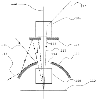
Figure 2 specifically details the ray path through both the panoramic and
forward components of the
omnidirectional optical system 100. For illustration simplicity, the panoramic
ray path is shown only on the left
side of Figure 2 and the forward ray path is shown on the right side. This
again is just for illustration, because both
CA 02555214 2006-08-03
WO 2005/078502 PCT/US2005/003215
forward and panoramic rays are processed from all directions. Referring also
to Figure 3, Figure 2 details the rays
at the rear boundary extremes of the panoramic field of view 320, inbound
along path 214. A ray 216, forward but
along the periphery, traces a path to the primary reflector 102" is then
reflected to secondary reflector 104, and is
again reflected through primary reflector hole 114 along the optical axis 112.
It then passes to the focusing lens
group x08 and the image plane 110, see Figure 1. Similarly, the rear boundary
ray 214 traces the path from the
periphery to the primary reflector 102, to the secondary reflector 104, and
through primary reflector hole 114 to
focusing lens group 108 and onto image plane 110, again refer also to Figure
1. On the right side of Figure 2, the
path of a forward ray 215 traces a path through the forward imaging lens group
106, in which it is refracted, then
passes through the secondary reflector hole 116., through primary reflector
hole 114, through focusing lens group
108 and onto image plane 110.
An integrated function of both the primary reflector 102 and secondary
reflector 104 is to ensure the
seamless boundary between the forward field of view 318 and the panoramic
field of view 320. The geometry and
size of the primary and secondary reflectors 102, 104 define the boundaries of
the panoramic field of view 320 and
is matched exactly to the boundary of the forward field of view 318 with no
overlap and no gap. Additionally, the
geometry of the primary and secondary reflectors 102, 104 defines the F/#1 of
the panoramic field of view 320. The
F/# can be interpreted as the brightness in the resultant image presented on
the image plane 110 and the speed of the
optical system. By matching the F/# of the panoramic-only optical system
(primary reflector 102 plus the
secondary reflector 104) with the F/# of the forward-only optical system
(forward imaging lens group 106), the
brightness appears consistent over the entire image on the image plane 110.
Forward imaging lens group 106 is designed to collect the forward field of
view 318 and transfer it through
the focusing lens group 108 to the image plane 110, so that the image striking
image plane 110 captures a smooth,
integrated representation of the fields of view 318, 320 and 322 with minimal
gaps or overlaps. The forward
imaging lens group 106 which is selected for a given application defines the
boundaries of forward field of view
318 boundaries and also defines the F/# of the forward field of view 318. In
the preferred embodiment, forward
field of view 318 spans approximately 80 degrees, +/- 40 degrees about optical
axis 112. The forward imaging lens
group 106 is placed directly behind the secondary reflector 104 with respect
to the image plane 110 (i.e., directly
forward of secondary reflector 104 with respect to the forward field of view)
and is substantially centered on optical
axis 112. In the preferred embodiment the lens elements in the forward imaging
lens group 106 are spherical
optical components fabricated of conventional optical materials such as BK7.
The use of spherical optics and
conventional materials lends to lower fabrication costs and cost effective
system implementation. Of course, other
suitable field collecting elements known or which may become known in the art
may also be suitable for lens group
106 fox a given application.
Focusing lens group 108 is centered along optical axis 112 and is placed in
between primary reflector 102
and the image plane 110. The focusing lens group 108 collects the panoramic
field of view 320 from the secondary
reflector 104 together with the forward field of view 318 from the forward
imaging lens group 106, as an integrated
image. It is the function of the focusing lens group 108 to focus the two
independent optical paths from the
panoramic field of view 320 and the forward field of view 318 onto a single
image plane 110 and to control the
image aberrations on this coplanar image. In other words, in general, the
geometry and diameter of primary
reflector 102, the geometry of secondary reflector 104, the diameter of
primary reflector hole 114, the diameter of
secondary reflector hole 116, particular optical properties of forward imaging
lens group 106, and the particular
1 The expression denoting the ratio of the equivalent focal length of a lens
to the diameter of its entrance pupil. See,
e.g.,
http://www.photonics.com/dictionary/lookup/XQ/ASP/url.lookup/entrynum.5806/lett
er.f/pu./QX/lookup.htm
CA 02555214 2006-08-03
WO 2005/078502 PCT/US2005/003215
optical properties of focusing lens group 108, as well as the separations of
these various elements one from another
along optical axis 112, combine as free parameters to determine exactly what
sort of image is delivered to image
plane 112, and are varied based on the particular application.
In the preferred embodiment, primary reflector 102 houses a portion of the
focusing lems group 108 in the
concave underside of its reflective surface. In the preferred embodiment the
lens elements in the focusing lens
group 108 are spherical optical components fabricated of conventional optical
materials such as BK7. The use of
spherical optics and conventional materials lends to lower fabrication costs
and cost effective system
implementation. Of course, other suitable focusing elements known or which may
become known in the art may
also be suitable for lens group 108 for a given application.
Iznage l Detection Plazze
The forward field of view 318 and panoramic field of view 320 are integrated
on a single image / detection
plane 110 to be presented as a single image. Figure 4 shows a schematic
representation of the integrated image on
the image plane 110 with the coplanar presentation of the forward field of
view 318 and the panoramic field of view
320. The coplanar single image presents many options for post processing not
available to imaging systems that
require panning and tilting to cover the same total field of view. Image
processing techniques can be employed to
remap the integrated image on image plane 110 and present it to the user in a
variety of formats. The image plane
110 is the focus of the coplanar integration of the forward field of view 318
and the panoramic field of view 320.
As shown in Figure 4 the forward field of view 318 is concentrically presented
with the panoramic field of view
320. Although a boundary between the forward field of view 318 and the
panoramic field of view 320 is illustrated
on the schematic in Figure 3, this is only to illustrate the difference
between the image collected by the forward
imaging lens group 106 and that collected by the primary reflector 102. In
actuality the omnidirectional optical
system 100 produces a continuous, ifztegz~ated image on image plane 110 in
which the boundary between the fields
of view is not evident. The image plane 110 preferably comprises a visible or
near-infrared optical / imaging
detector such as a CCD or CMOS camera or detector. The preferred embodiment is
optimized for integration with
a 640 x 480 output file size on a 1/3" format sensor, though this is
illustrative and not in any way limiting.
Alternative embodiments are optimized for visible and near-IR sensors of
various sizes and resolutions. The
sensors can either be analog or digital and can range from the lowest
resolution, approximately 160 x 120 pixels to
the highest resolution, which at this time is greater than a 6 megapixel array
and may increase in the future within
the scope of this disclosure and its associated claims.
Fields of View
The illustrated embodiment provides an omnidirectional optical system 100 with
a substantially hyper-
hemispherical field of view that extends to a maximum 270 degrees vertically
(forward) and 360 degrees
peripherally as shown in Figure 3. This field of view is achieved by
seamlessly integrating a forward field of view
318 with a panoramic field of view 320 on a single image plane 110. The
forward and panoramic fields of view
318, 320 are non-overlapping and there is no blind spot or gap between them.
The boundaries of the forward and
panoramic fields of view 318, 320 are relatively parallel; in particular, they
gently converge and eventually overlap.
The forward field of view 318 extends about 80 degrees total (+/- 40 degrees
from the optical axis). The panoramic
field of view 320 extends about 95 degrees (50 degrees above the horizon and
45 degrees below the horizon. The
magnification, and the F/#, are matched between the forward and panoramic
fields of view 318, 320. The image
formed on the image plane 110, therefore, seems continuous, with no
differences in brightness or size, and no
CA 02555214 2006-08-03
WO 2005/078502 PCT/US2005/003215
distortion at the seamless boundaries. The geometries of primary reflector 102
and secondary reflector 104 define
the extent of the panoramic field of view 320. Similarly the optical design of
the forward imaging lens group 106
defines the extent of the forward field of view 318. The extent of each the
forward field of view 318 and the
panoramic field of view 320 can be tailored to meet the exact specifications
of the application in which the
omnidirectional optical system 100 is being used.
Size and Matef~ials
The invention has been experimentally demonstrated at a diameter of
approximately 40 mm and a height
of 62.5 mm for a omnidirectional optical system 100 optimized for a visible
light images. The invention disclosed
can be scaled in diameter to accommodate different application requirements.
It has been scaled, experimentally, to
a diameter of 2.7 mm for endoscope / borescope applications. The exact
specification of materials is application
dependent. However, for example, and without limitation, the preferred
embodiment comprises a primary reflector
102 that is BIC7 glass with a protected aluminum coating, a secondary
reflector 104 made of polished aluminum,
and all optical elements in the forward imaging lens group 106 and the
focusing lens group 108 made of standard
glass with an antireflection coating deposited on them.
Altes~faative Embodinaents
Aside from the alternative embodiments listed above relating to individual
component specification and
application customization, additional embodiments are now discussed. One
alternative embodiment comprises the
omnidirectional optical system 100 optimized for integration with an infrared
imaging sensor for thermal or far-
infrared imaging, such as but not limited to an uncooled microbolometer or a
focal plane array. This detector /
sensor is inserted at the image plane 110 of the optical system 100. The
wavelength differences in the signal being
transmitted and processed require different optical materials, which have
different optical properties and a system
optimized to the microbolometer size and resolution. At this time the highest
resolution for infrared uncooled
microbolometer is 320x240 pixels. Specifically, distinct changes in the
optical materials are necessary to account
for the infrared band of the electromagnetic spectrum. In this embodiment, the
primary reflector 102 and the
secondary reflector 104 preferably are coated in gold. This is the standard
for IR reflective coatings and is widely
available from optical manufacturers. The choice of materials for the optical
elements in the forward imaging lens
group 106 and the focusing lens group 108 include, but are not limited to,
Zinc Selenide (ZnSe), Sodium Chloride
(NaCI) and Cesium Bromide (CsBr).
An additional alternative embodiment of the present invention is
implementation of the omnidirectional
optical system in a non-imaging application for omnidirectional free space
communication. This alternative
embodiment in which the omnidirectional optical system 100 is used as an
omnidirectional optical antenna is
depicted in Figure 5, though it is pointed out that the light ray paths shown
in Figure 5 as well as the overall
combination of elements is configured in the same manner as Figure 1.
The primary components of the omnidirectional optical system 100 remain the
same in this alternative
embodiment and comprise primary reflector 102, secondary reflector 104,
forward lens group 106 and focusing~lens
group 108. In this embodiment, the primary reflector 102 and the secondary
reflector 104 are large area light
collectors to feed light from the panoramic field of view 320 into the
focusing lens group 108. Second, the forward
lens group 106 is used as a wide-angle objective to bend the light from the
wide-angle forward field of view 318
into the focusing lens group 108. Third, the focusing lens group 108 comprises
a set of front positive lenses and a
set of rear negative lenses.
CA 02555214 2006-08-03
WO 2005/078502 PCT/US2005/003215
In this alternative embodiment, the optical system is modified to be employed
as an afocal system. This
modification include only the focusing lens group 108. In other words, this
system comprises at least one afocal
element 108, rearward of primary reflector 102 relative to the forward field,
substantially centered about the optical
axis 112, as illustrated. The image plane 110 is set at infinity, which is
represented by the parallel rays 502 (rather
than focused) emanating from the focusing lens group 108 in Figure 5. The
afocal magnification is maintained at
an optimized level, which depends on the detector/transmitter size and the
overall dimensions of the optical system.
In this alternative embodiment, for this long-range optical communication
antenna application, especially
for high data rate communication systems, a diffraction limited optical system
design is required. If the design is
not diffraction limited, wavefront errors may overlap the adjacent optical
signals and confuse the decision-making
circuits when the data rate reaches a certain level. The optical system forms
the transmit beam and any errors can
degrade the beam quality. Optimization depends upon the on lens configuration
for the forward lens group 106 and
the focusing lens group 108 and glass materials selection.
In this alternative optical antenna embodiment, the image plane / detector
plane 110 must be distortion
free. For an afocal optical system, the power distribution on image plane 110
is expected to be constant across the
total field of view, which comprises the forward field of view 318 plus the
panoramic field of view 320. Any
distortion will alter the transmitter power distribution, and will saturate
the detector or weaken the signal strength.
As mentioned above, the distortion free omnidirectional optical design is
achievable by using either a convex
hyperbolic or a convex parabolic mirror as the primary reflector 102.
A final alternative embodiment includes directional zooming. Due to the unique
configuration of the
disclosed omnidirectional optical system 100, directional zooming in the
panoramic field of view 320 can be
achieved by tilting the primary reflector 102 relative to optical axis 112,
which is typically spherical or alternatively
parabolic or parabolic. This alternative embodiment is illustrated in Figure
6. Tilting the primary reflector 102 in
the direction of interest changes the area on the primary reflector 102 that
the image rays strike and the total path
length, thereby changing the size of the image on the image plane 110. The
forward field of view 318 either moves
away from the center of image plane.110 or completely out of view, depending
on the degree of tilt of primary
reflector 102. However, this would not be a factor in the imaging since the
zoomed area is the area of interest. It is
expected that this configuration can achieve at least a Sx zoom on the area of
interest. Additionally, directional
zooming can be achieved in the forward field of view 318 by moving at least
one of the elements of the forward
viewing lens group 106 along the optical axis 110.
Directional zooming can be implemented by incorporating a 360 degree
rotational and two linear actuators
in the support structure that holds the elements of the optical system 100.
Depending on the specific size of the
optical system 100 implemented, miniature rotation and linear actuators can be
used. In one implementation, the
rotational actuator can hold the two linear actuators at 180 degrees from each
other beneath the base of the primary
reflector 102. Directional zooming can be achieved by positioning the linear
actuators at the desired position with
the rotational actuator, the moving them in opposing directions to effect the
desired tilt on the primary reflector 102.
Miniature linear actuators can be incorporated in the structural support of
the optical elements to properly align and
position the elements based on the desired performance specifications of the
optical system 100. Other options for
achieving this will be apparent to someone of ordinary skill in the mechanical
arts, and are regarded within the
scope of this disclosure and its associated claims.
In conclusion, the optical system 100, in the various embodiments disclosed
herein, provides the ability to
collect signals from a continuous field over 360 degrees panoramically and
approximately 270 degrees vertically.
This technology has widespread medical, surveillance, military, communications
and inspection applications.
CA 02555214 2006-08-03
WO 2005/078502 PCT/US2005/003215
Medically, it can be integrated with various current and future internal
imaging technologies including flexible and
rigid endoscopes. The continuous extremely wide field of view provides
unmatched capabilities for imaging across
virtually all medical disciplines. Surveillance applications of optical system
100 are numerous. Mounted systems
can provide extremely wide continuous fields of view and the system can be
mounted in the forward position,
ceiling mounted, or upright post mounted. The system can be used for either
interior or exterior surveillance
applications including but not limited to security, casino action monitoring,
retail store monitoring, home
monitoring and perimeter detection. Due to the extremely wide field of view
it,eliminates the need for pan and tilt
systems that scan areas and also allows for the integration of commercial
motion detection software. Wireless
communication technology can be utilized with the compact optical system 100
to achieve remote surveillance
capabilities. Military applications expand on the surveillance applications,
providing surveillance and navigation
technology for unmanned aerial and ground vehicles. Multiple systems can be
linked to a remote monitoring
station to provide widespread perimeter detection to a military post or
installation. Finally, optical system 100 can
be utilized for free space communication applications as an optical antenna.
The wide field provides an ideal
antenna for building to building, UAV to UAV, UAV to satellite, UAV to ground,
and satellite to satellite
communication. Optical inspection applications span many disciplines.
Integrated in an industrial borescope, or a
large scale pipe crawler, provides inspection ability to pipes or bores of all
sizes. An additional inspection
application is undercarriage vehicle inspection at checkpoints. Mounted on a
base that vehicles drive over, it can
provide single image inspection of the undercarriage of a vehicle and allow
for means of image processing
techniques for foreign object identification.
While these are examples of the many diverse applications to which optical
system 100 is suited, it is
important to recognize that this system is in fact suited to any application
where is it desirable to receive and
process signals over a full 360 degree panoramic view, as well as 270 degrees
in the forward / vertical direction, in
a seamless manner. Thus, the application of this technology to any application
which requires such panoramic and
forward / vertical viewing is regarded as being within the scope of this
disclosure and its associated claims.
While only certain preferred features of the invention have been illustrated
and described, many
modifications, changes and substitutions will occur to those skilled in the
art. It is, therefore, to be understood that
the appended claims are intended to cover all such modifications and changes
as fall within the true spirit of the
invention.