Note: Descriptions are shown in the official language in which they were submitted.
CA 02555464 2006-08-08
WO 2004/071568 PCT/DK2004/000100
A medical connector and a method of injection moulding such a connector
This invention relates to a medical connector for connecting a tube to a
medical device such as an insulin delivery device.
Such connectors are typically provided with means such as Luer-Lock type
means.for connecting the end of the connector which is opposite to the end
at which the tube is connected to the connector, to the medical device so as
to allow the connector to be disengaged from said device, this allowing the
medical device and/or the connector including the tube to be replaced.
EP 0 X53 323 A1 describes a coupling for joining the' ends of two tubes, said
coupling comprising a male part and a female parfi, both the male and female
part having means for attachment of the end of a tutae.
EP 0 151 519 describes a tube coupling comprising a male part and a female
part, both the male part and the female part comprising a tapered tube
connecting portion which is adapted to be inserted into the end of a tube.
EP 0 ~~5 501 13 describes a female coupling element of the Luer-Lock type
comprising an outer tubular body which is made of a relatively rigid moulded
thermoplastics mafierial and can be connected with a complimentary male
coupling element, and an inner sleeve which is made of a softer moulded
thermoplastics material which at one end is fitted within the outer body in
such a manner that the two parts are freely rotatable relative to each other
and at the opposite end comprises a cavity for connection to e.g. a tube.
Furthermore, medical connectors consisting of a single plastics material and
manufactured by injection moulding are known.
Such medical connectors comprise a through-going bore, one end of said
connector being adapted to be connected with the end of a tube by gluing so
as to form a permanent connection and the opposite end comprising a part of
CA 02555464 2006-08-08
WO 2004/071568 PCT/DK2004/000100
2
a Luer-Lock type connection for connecting the connector to a medical
device such as an insulin pump.
Due to the fact that an injection moulding process is a simple manufacturing
method, such medical connectors can be manufactured at low costs.
However, these medical connectors suffer from a drawback.
Thus, prior to the use of a medical connector it has to be disinfected which
ordinarily is effected by wiping it with a liquid disinfectant such as ethyl
alcohol.
Such a treatmenfi may cause stresses in some plastics material to be
released during physical strain and may result in the formation of cracks
which bring aboufi leaks.
The selection of a plastics material which is resisfianfi to fibs influence of
disinfecfianfis may cause another problem, vii. thafi fibs permanent
connection
of fibs fiube end to fibs connecfior has to be effiecfied by means of a~ hard
glue.
The use of a hard glue in confirasfi to a soft glue resulfis in an inflexible
connecfiion between fibs tube and fibs connecfior and may resulfi in a
leakage.
In the previously known connecfiors composed of two plastics materials, such
as those described in EP 0 775 501 B, the two parts have to be made
separafiely and be assembled afterwards. This increases the production costs
compared to connectors which can be injection moulded in one-piece.
The object of the present invention is to provide a medical connector which
can be manufactured in large quantities at low costs and which is more
resistant to leakage than the prior art medical connectors.
According to the invention there is provided a medical connector of the above
mentioned type having a through-going bore which at one end of the
connector comprises a cavity for permanently attaching the end of the tube to
CA 02555464 2006-08-08
WO 2004/071568 PCT/DK2004/000100
3
the connector and which at least at said end of the connector comprises an
inner part and an outer part; the inner and outer parts being integrally
connected, the outer part being made from a thermoplastics material which is
resistant to changes when subjected to the influence of a disinfectant and the
inner part being made from a thermoplastics material which is compatible
with a soft glue.
The term integrally connected is to be understood as the two parts are
connected in such way that they are unable to rotate independently around
the longitudinal axis.
This new type of connectors is easy and cheap to produce. They are
resistant to the mandatory disinfection prior to use and they have a flexible
but permanent attachment of the tube to the connector.
According to fihe invention there is further provided a method for injection
moulding of a connector of the above mentioned type comprising the steps of
- injecting a plastics material which is compatible with a soft glue into a
mould having a cavity of the desired shape and a core of the desired
shape for forming a cavity in the connector for permanently atfiaching an
end of a tube
- injecting a plastics material which is resistant to changes when subjected
to the influence of a disinfectant infix a mould having a cavity of the
desired
shape, a core for creating a through-going opening
- using a part of the surface of the firstly injected plastics material as
part of
the mould receiving the secondly injected plastics material.
In one embodiment of the invention the connector comprises means for
connecting the connector to a medical device such as an insulin pump, said
CA 02555464 2006-08-08
WO 2004/071568 PCT/DK2004/000100
4
means preferably being in form of a Luer-Lock type, and more preferably the
means are capable of receiving the male part of the Luer-Lock type.
In a preferred embodiment the term integrally connected further implies that
the two parts are unable to move independently along the length axis.
Preferably the connector comprises means for getting a better hold of the
connector, which can be advantageous when connecting or disconnecting
the connector to a medical device. Said means can be but are not limited to a
groove, a ribbon, a rim, preferably the means are in form of a groove.
Preferably said means are placed in the same end as fihe tube is supposed to
be attached.
In another embodiment of the invention the inner part and the outer part of
the connector are capable of rocking relative to each other thereby providing
a more flexible but still permanent connection to the tube. This reduces the
risk of leakage even further.
In a preferred embodiment the cavity of the inner part of the connector has
an increasing diameter towards the outer end of the inner part, preferably a
part of the cavity has a conical shape. Preferably, the conical part forms an
angle of at least 15 degrees relative to the central axis, preferably the
angle
is between 20 and 25 degrees.
In another embodiment the cavity of the outer part at the end receiving the
tube also has an increasing diameter towards the outer end. Preferably at
least a part of the cavity of the outer part has a conical shape.
By using a conical-shaped cavity of the inner part and/or a cavity of the
outer
part with an increasing diameter an even more flexible connection between
CA 02555464 2006-08-08
WO 2004/071568 PCT/DK2004/000100
the connector and the tube can be achieved. Further, the increasing diameter
leaves more room for the soft and elastic glue.
In a preferred embodiment the diameter of the cavity of the inner part is
5 adapted to the diameter of the tube supposed to be permanently connected
with the connector.
Preferably the connector is constructed in such way that the inner part at
least in the area of connection between the connector and the tube is unable
to come into contact with the disinfectants. Preferably the plastics material
of
the inner part is selected exclusively from its gluing properties i.e. it is
compatible with a soft glue.
In one embodiment of the invention the delimiting part of the edge is flush
with the delimiting edge of the outer part or even broaches there around and
encloses portions of the outer faces of the outer part. In this case what
matters is that a sealing is provided to prevent the liquid from penetrating
from the outside and into the connecting area between the tube and the inner
part.
In another embodiment the outer part is moulded in such way that it encloses
the outer faces of the inner part so that during wiping with a disinfectant
connection between the disinfectant and the inner part of the connector
cannot be provided.
The connector with its permanently attached tube is preferably intended for
use for infusion kits where the luer lock is mounted to an insulin pump, while
the tube as such is connected to a syringe and an infusion part.
In another preferred embodiment the inner part and/or the outer part
comprises fasteners for fastening the inner part to the outer part or visa
CA 02555464 2006-08-08
WO 2004/071568 PCT/DK2004/000100
6
versa, more preferably the inner part has retention devices and the outer part
has grooves adapted to receive said retention devices. In an even more
preferred embodiment the retention devices are mounted on the outside of
the inner part and thereby providing a good retention between the inner part
and the outer part ensuring that the inner part cannot be loosened.
In another embodiment the inner part and the outer part are connected
and/or held together by means of a glue.
In another preferred embodiment the inner parfi, the glue and an area of the
tube are capable of forming an integral chemical connection.
Preferably the soft glue used in the permanenfi connection betv~een the tube
and the connector as a minimum has contact to both the tube and the inner
~ 5 part. It is of no consequence whether the glue further has contact to the
outer
part or not, it is only importanfi that the connection has an inner area which
is
unable to come into contact with the disinfectant used to wipe the connector
prior to use.
In a preferred embodiment the through-going bore of the outer part has a
central axis which is axially parallel and coincident with the central axis of
the
inner part.
In a preferred embodiment both the inner part and the outer part are made of
a thermoplastic material. In a more preferred embodiment the inner part is
made of an amorphous plastics material, preferably with a molecular
structure in which the chains are positioned randomly.
In a preferred embodiment the inner part is made of ABS. ABS is made of the
monomer components acrylic nitrite, butadiene and styrene. Each of the
three structural units adds valuable properties to the material. Acrylic
nitrite is
CA 02555464 2006-08-08
WO 2004/071568 PCT/DK2004/000100
7
responsible for the resistance and dimensional stability in heat. Butadiene
equips the material with tenacity and makes it resistant to impacts, while
styrene serves to ensure the rigidity of the material and easy processability.
ABS tolerates a number of acids, bases and oils with the proviso, however,
that the level of internal stresses is very low. There are a number of
solvents
that can dissolve ABS. Other suitable amorphous plastics materials include
e.g. polycarbonate, polystyrene, acrylic plastics, poly-methyl-methacrylate
and PVG.
In another preferred embodiment the outer part is made of a plastics material
also being a thermoplastics material and composed of at least one partially
plastics material, preferably a polypropylene is used. Polypropylene is a
partially crystalline plastics material in which the molecule chains are
located
in parallel with each other and form rather closely packed areas, the so-
~ 5 called crystallites. Polypropylene is a thermoplastics material with an
attractive balance between fihermal and chemical resistance and good
mechanical and electrical properties. Furthermore, polypropylene is immune
to bacteria and fungi. Additionally polypropylene is a plastics material
having
a very wide-ranging resistance to chemicals. It is resistant to salts, acids,
~0 bases (inorganic) and alcohols and some oils. In principle, it is the
crystallite
that is decisive to the resistance to chemicals. Also other materials can be
used for the outer part e.g. polyamide, polyethylene, poly-ethylene-ether-
ketone (PEEK).
~5 A crystalline plastics material is characterised in that the molecules are
situated closely adjoining each other whereby the intermolecular forces act
more strongly and more energy is to be supplied in order to overcome it. In
practice this means that crystalline plastics/partially crystalline plastics
generally have a higher temperature of vitrification and a higher melting
point
30 than amorphous materials. The crystalline areas in the material have a
CA 02555464 2006-08-08
WO 2004/071568 PCT/DK2004/000100
distributing effect on light and therefore crystalline and partially
crystalline
plastics have a milky appearance.
A thermoplastics material has the characteristic feature that it exhibits
three
different, more or less sharply delimiting state areas as a function of the
temperature, viz. a solid state, a rubber elastic state and a viscous state.
Upon heating the material becomes soft and assumes a rather more solid
structure upon cooling and, in principle, it is possible to shape it several
times.
The following physical, mechanical properties apply to a soft glue versus a
hard glue.
~~ft glue Hard Tae
Extension at 120/~-240/~0/~-50/~
break
Hardness shore ~25-~60 ~65-~90
~
In a preferred embodiment the connector is adapted to receive means for
supporting the attachment of the tube. Said means are suitable for securing
the tube to the connector until the glue is hardened.
~uring attachment of the tube to the connector it is preferred to have a final
hardening after the glue is mounted between the connector and the tube.
Further it is preferred that the connector is adapted to firap and secure the
tube until the glue has set.
The invention also relates to an infusion unit manufactured from the
connector and wherein the end opposite to the tube is connected to an
CA 02555464 2006-08-08
WO 2004/071568 PCT/DK2004/000100
9
insulin pump by means of a luer-lock and wherein a soft glue is used to
connect the tube to the connector.
In a preferred method of producing said connectors a plastics material which
is compatible with a soft glue is injected into the mould under a suitable
pressure for providing the inner part, subsequently under a suitable second
pressure a plastics material being resistant to changes when subjected to the
influence of a disinfectant is injected into the mould. Following such
moulding
of the connector, said moulding taking place e.g. in accordance with
principles like the ones given in patent f'Jo. W~ 00/73040 and W~ 93/35303,
an opening of the mould takes place and the connectors are ejected from
their cores. ~ptionally a subsequent assembly process between the
connector and a tube takes place as described above by means of a soft
glue.
15'
In the following a preferred embodiment of the invention will be described
with reference to the figures.
Figures 1A-~ show an example of a connecting element according fio the
~0 invention seen from two different sides;
Figure 2 is a sectional view along II-II in Figure 1A;
Figure 3 is a sectional view of the outer part in detailed form;
Figure 4 is a sectional view of the inner part in detailed form;
Figure 5 shows the disclosures of Figure 2 with a plastics tube mounted in
the inner part.
CA 02555464 2006-08-08
WO 2004/071568 PCT/DK2004/000100
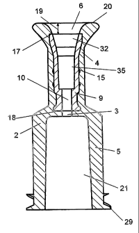
Figures 1A and 1 B show a connector 1, seen from the side in a first position
and turned by 90°. The connector, see also Figure 2, comprises an outer
part
2 which is preferably made of a thermoplastics material that is chemically
resistant to disinfectant such as ethyl alcohol. The outer part comprises an
5 end 4 for receiving a tube and an end 5 for connecting to a medical device
such as an insulin pump. The end 4 for receiving a tube comprises a cavity 6
as it is also seen in the sectional view in Figure 2.
The end 5 for connecting to a medical device comprises a luer lock 21 in
10 which a male luer-lock is preferably used. Finally the end 5 comprises an
external double-thread 29 for being mounted to preferably an insulin pump.
The outer shape of the connector 1 is such that it is essentially
cylindrically
shaped, beat wherein the end 4~ for receiving fihe tube has a narrowed portion
for providing an oval narrowing area 23. This serves to improve the gripping
around the connector° 1 during handling thereof. The outer part 2 has
an
outer essentially plane upper delimiting face 20. The distance from this and
down to the lower delimiting face 34 is within the range 17 mm.
Figure 2 is a sectional ~siew wherein the joining between the two elements
that constitute the connecfior 1 vii. the oufier part 2 and the inner part 9
will
appear. The outer part is manufactured such that there is liquid
communication throughout its entire passage and it comprises axially a
passage throughout its entire interior, wherein, in its end 5, it has such
shape
that it forms a leer lock 21. From said luer lock 21 an axial opening 3 fio
the
cavity 6 is provided. The central axis of the opening 3 is axially parallel
and
coinciding with a through-going opening 10 provided in the inner part 9. In
the
opposite end of the inner part 9 there is a section called the connector part
32 for the tube which is configured with side faces that diverge outwards
towards an upper delimiting face 17, where said delimiting face 17 is of plane
configuration.
CA 02555464 2006-08-08
WO 2004/071568 PCT/DK2004/000100
11
In the area between the tube connector part 32 and the otherwise
cylindrically shaped opening 10 the interior area 35 and a further essentially
conically shaped connecting area that may also constitute a part of the tube
connector part and serve as glue reservoir are situated. The interior area is
situated so that the glue ensuring connection between the tube and the inner
part cannot be in liquid communication with the exterior of the connector. The
inner part 9 is located so that its upper delimiting face17 is located at a
distance from the upper delimiting face 20 of the outer part 2 as such. It
should further be mentioned that the inner part 9 has on its outer
circumference retention devices 15 e.g. in form of studs or wings that serve
as undercuts whereby good gripping is ensured during moulding between the
inner part 9 and the outer part 2.
The outer part 2 will be described with reference to Figure 3. The outer part
2
comprises as mentioned an essentially oufier cylindrically shaped sleeve
having essentially three cavities; a cavity in the end 5 comprising a lust
lock
21 and preferably a male lust lock from which there is connection via a
central opening 3 to the cavity 6 in the end of the outer part 2 for attaching
the tube which interior faces are shaped to be essentially congruent with the
outer faces of the inner part. The outer part 2 is manufactured from a
chemically resistant material 13, whereby no stresses are released when it is
wiped with e.g. ethyl alcohol.
The inner part 9 will be described with reference to Figure ~.. It also
comprises a sleeve-like construction, its outer walls 14 being essentially
cylindrical with various pouches/retention devices mounted thereon for
providing good retention between the inner part and the outer part.
The cavity of the inner part comprises essentially four areas, viz. a through-
going opening 10 in communication with the inner area 35 being an
essentially cylindrical area having a length of essentially about 3 mm and
CA 02555464 2006-08-08
WO 2004/071568 PCT/DK2004/000100
12
with a somewhat larger diameter than the opening 10; a conical area of about
1 mm forming the connection between the inner area and the tube connector
part 32; and said tube connector part constituting the upper part of the inner
part 9. This tube connector part is configured such that the walls diverge
outwards towards the upper delimiting face 17 of the inner part 9 said face 17
being of essentially plane configuration. As mentioned the outer walls of the
inner part also comprise retention devices 15.
The connection between the tube and the inner part including the tube
connector part 32 that may also be an area where the glue bonds and seals
the remaining entrance, will be described in further defiail with reference to
Figure 5. It shows the joint between a connector 1 and a tube 24, wherein a
secfiion has been made fihrough the connecting elemenfi and the tubular
elemenfi. A luer-lock is shown and opposite fio fihafi the tubular elemenfi is
located in fibs inner park 9 of the connecting elemenfi corresponding to the
inner area 35. It is nofied in this content fihafi fibs tube connector part 32
is
situafied so thafi its upper delimiting face is located at a disfiance from
the
upper delimitafiing face 20 of fibs outer park. lNhen the fiube seines fibs
tube
connecfior park 32, and wherein - between the outer face of fibs fiube 2~ and
fibs inner face of the tube connecfior park 32 - attachmenfi means 3 are
located in the form of a soft glue, the risk of chemicals, if any, used for
wiping
the outer face of the outer part penetrating downwards to the inner area 35 of
the inner part as such will be small due, on the one hand to said distance
and, on the other hand, to the sealing properties of the glue. This is
essential
since the inner park is manufactured precisely from a plastics material fihat
provides good connection to the tube when a soft glue is selected. This
plastics material is not resistant to the material used for wiping.
Conversely, a
material that tolerates wiping with chemicals, including e.g. ethyl alcohol
can
be used for the outer part.
CA 02555464 2006-08-08
WO 2004/071568 PCT/DK2004/000100
13
It should be noted with regard to soft glue that it is inherently more
flexible
than hard glue. A soft glue is used precisely in order to enable the plastic
tube to retain its flexibility in the in-use situation.