Note: Descriptions are shown in the official language in which they were submitted.
CA 02555756 2006-08-10
- 1 -
TITLE:
[0001] Thermally Insulated Pipe For Use at Very High Temperatures
FIELD OF INVENTION
[0002] The present invention relates to insulated pipes comprising a
thermal insulation system particularly for use at very high operating
temperatures and having very low heat loss and insulation thickness in
comparison with conventional high temperature insulation systems used with
pipes.
BACKGROUND
[0003] Structures used to store or transport materials at temperatures
exceeding the temperature of the surroundings are often coated with materials
that retard the flow of heat to the surroundings. Pipelines and other
structures
employed in transporting oil, natural gas, petroleum products and other
products
are often insulated to maintain a temperature such that the contents remain
sufficiently warm to be flowable, or to prevent the precipitation of
components
such as wax (from crude oil) or hydrogen sulphide hydrates (from raw gas).
Pipelines are also used to transport heated water for use in district heating,
in
which case it is important to minimize the loss of stored energy contained
within
the heated water and to maximize the efficiency of heat exchangers needed to
extract said stored energy.
[0004] Traditionally such structures have operated at temperatures
sufficiently low that they could be insulated with closed cell, water-
resistant
organic foams, such as polyurethane or polyisocyanurate foams. However,
several important applications require the use of operating temperatures in
excess of those which traditional closed-cell polymeric foams can withstand.
These applications include the extraction of oil from very deep wells, the
transport over long distances of bitumen, the transport of steam for injection
into
heavy oil wells or to extend the useful production life of older wells, and
the use
of steam or hot water-based district heating systems. These new high
temperature applications may require insulation systems designed to operate
CA 02555756 2006-08-10
-2-
continuously at operating temperatures exceeding 150 C, for a minimum of 20-
30 years. Service temperature limitations of polymeric foams such as
polyurethane (PUF) and polyisocyanurate (PIF) materials for continuous long-
term use, however, are limited to approximately 150 C. There is thus a need
for
thermal insulation systems that can operate at temperatures exceeding 150 C
while retaining or exceeding the thermal insulation efficiency of existing
closed-
cell foam systems.
[0005] For these high temperature applications, it is known to use inorganic
insulations that can withstand much higher temperatures. Examples of such
inorganic insulation systems include foamed glass, fibre mats formed from
glass
or spun minerals, and preformed half shells based on calcium silicate, an
example of which is sold under the trade name Thermo-12. Other examples
include mineral fillers and mortars such as perlite (an expanded mineral), and
calcium silicate. However, such inorganic insulation materials suffer a number
of
very significant drawbacks. In all cases, the thermal conductivity is much
higher
than that of closed cell organic foams, thus requiring very great thickness in
order to achieve an acceptable level of heat retention. Furthermore, with the
exception of foamed glass, all are extremely permeable to water. If such
materials come into contact with water, such as from a leak in the outer
jacket
protecting the insulation from the elements, the inorganic insulation will
become
sodden and it will no longer act as a thermal insulation. Glass foam, which is
primarily closed cell and therefore less inclined to absorb water, is
extremely
abrasive, and will destroy any anti-corrosion coating applied to protect the
pipe
as a consequence of the large differential expansion that high temperature
pipelines undergo on startup and in service.
[0006] For these high temperature applications, it is also known to use
composite insulation designs comprising a heat resistant insulator as the
initial
layer adjacent to the surface overlaid by a conventional thermally efficient
closed-cell lower temperature rated organic insulation. The heat resistant
insulation layer provides a thermal barrier effect, lowering the transmitted
temperature to a level such that the exposure temperature of the overlaid
organic foam materials can be maintained within the allowable limits for the
organic material. This combination of materials produces an insulation system
CA 02555756 2006-08-10
-3-
that can operate at much higher temperature than the organic foam insulation
can by itself, but at a considerable sacrifice in insulation efficiency in
comparison
with a system using only the organic-based thermal insulation.
[0007] Composite insulation systems for high service temperatures have
previously incorporated as thermal barrier layers materials such as glass
wool,
mineral fibre (also known as "rock wool"), preformed half shells based on
calcium
silicate, asbestos, or foam glass, mineral fillers and mortars such as perlite
and
calcium silicate, or various combinations of these materials. These were then
typically overlaid with PUF, PIF or phenolic foam.
[0008] In the particular case of buried pipelines, currently used composite
insulation systems for high service temperature have numerous disadvantages.
Traditional thermal barriers have relatively poor insulation value,
necessitating
the application of a considerable thickness to lower the temperature
transmitted
to the foam layer. Furthermore, many of these mineral based materials such as
rock wool can be very labor intensive to apply, or in the case of mortar based
materials such as perlite may require complex processing such as molding and
autoclave baking in order to be cured properly. Some high temperature
insulation systems use insulation materials (eg. loose perlite or vermiculite
filler)
that need to be contained within another pipe in order to be held in place and
protected from the environment. Many insulation materials for high service
temperatures have comparatively poor insulation or physical strength
properties
(eg. mineral or glass wools) and will not directly support the weight of the
pipe
for buried pipe systems. Because of the low compressive strength of many of
the high temperature insulation materials (e.g. rock wool, or aerogel stand-
alone
insulation), they are primarily used for above ground pipelines. For direct
burial
they must be encased within a pipe-in-pipe (PIP) assembly. Both of these
solutions can be extremely expensive to apply and install compared to a
factory
applied single pipe insulated system for buried service.
[0009] For high temperature systems, it is advantageous for the barrier
layer to have a thermal insulating capability at least equal to, and
preferably
better than that of a PUF or PIF overlayer. In the particular case of tubular
structures, such as pipes, the ability to contain heat flow decreases as the
CA 02555756 2006-08-10
-4-
diameter increases. Therefore, it is highly advantageous to minimize the
additional increased diameter that results when additional layers of
insulation are
added. This is particularly true with smaller diameter pipes.
[00010] Figure 1 illustrates three different situations for the relative
insulating values of a multilayer insulated pipe. If the outer insulation is
much
more efficient than the inner insulation, even small increases in the
thickness of
the outer layer will require substantial increases in the thickness of the
inner
layer in order to maintain the interface between the two insulations at a
temperature that the outer layer can withstand. If, on the other hand, the
inner
insulation has a lower thermal conductivity than the outer layer, only small
increases in the thickness of the innermost layer of insulation will be
required to
reduce the interface temperature to the desired temperature. Thus, the
thickness
of the inner layer can be kept much lower, and the system design can be much
more efficient.
SUMMARY OF INVENTION
[00011] In one aspect, the present invention provides an insulated pipe
comprising a pipe and a composite insulation system, said composite insulation
system comprising: (a) a first insulation layer comprising a first insulation
material having a thermal conductivity k-factor value of less than 0.023 W/m-K
at 38 C; (b) at least one additional insulation layer comprising an insulation
material having a thermal conductivity k-factor greater than that of the first
insulation material and a maximum operating temperature limit less than that
of
the first insulation layer, said composite insulation system bonded to an
exterior
surface of said pipe with the first insulation layer facing towards said
exterior
surface of said pipe; wherein at least one of said first insulation layer or
said at
least one additional layer extends continuously about said exterior surface of
the
pipe.
[00012] In another aspect, the present invention provides an insulated pipe
for use in an undersea pipeline, comprising: a pipe; a composite insulation
system, said composite insulation system comprising: (a) a first insulation
layer
comprising a first insulation material having a thermal conductivity k-factor
value
of less than 0.023 W/m-K at 38 C; (b) at least one additional insulation layer
CA 02555756 2006-08-10
-5-
comprising an insulation material having a thermal conductivity k-factor
greater
than that of the first insulation material and a maximum operating temperature
limit less than that of the first insulation layer, said composite insulation
system
bonded to an exterior surface of said pipe with the first insulation layer
facing
towards said exterior surface of said pipe; wherein said composite insulation
system is formed by application of the first insulation layer to the exterior
surface of the pipe followed by application of an additional insulation layer
to
surround said first insulation layer, wherein at least one of said first
insulation
layer or said at least one additional layer extends continuously about said
exterior surface of the pipe; and an outer jacket covering the composite
insulation system, said outer jacket protecting the composite insulation
system
and pipe from water ingress and from ambient pressure.
[00013] In a further aspect, the present invention provides an insulated pipe
for use in a subterranean pipeline, comprising: a pipe; a composite insulation
system, said composite insulation system comprising: (a) a first insulation
layer
comprising a first insulation material having a thermal conductivity k-factor
value
of less than 0.023 W/m-K at 38 C; (b)at least one additional insulation layer
comprising an insulation material having a thermal conductivity k-factor
greater
than that of the first insulation material and a maximum operating temperature
limit less than that of the first insulation layer, said composite insulation
system
bonded to an exterior surface of said pipe with the first insulation layer
facing
towards said exterior surface of said pipe; wherein at least one of said first
insulation layer or said at least one additional layer extends continuously
about
said exterior surface of the pipe; at least one of a bonding layer and/or
reinforcement layer for securing said composite insulation system to said
pipe,
said at least one bonding layer and/or reinforcement layer protecting the
composite insulation system from soil stress forces; and an outer jacket
covering
the composite insulation system, said outer jacket protecting the composite
insulation system and pipe from water ingress.
[00014] In an embodiment of the invention, the insulated pipe for use in a
subsea or a subterranean pipeline comprises an outer jacket which is a
watertight polymeric covering.
CA 02555756 2006-08-10
-6-
[00015] In a further embodiment of the invention, the watertight polymeric
covering comprises an extruded polymeric material.
[00016] In a further embodiment of the invention, the watertight polymeric
covering comprises an extruded polyolefin.
[00017] In a further embodiment of the invention, the watertight polymeric
covering comprises an extruded polyamide.
[00018] In a further embodiment of the invention, the watertight polymeric
covering comprises an extruded elastomer.
[00019] In a further embodiment of the invention, the watertight polymeric
covering comprises a thermoset polymeric material.
[00020] In a further embodiment of the invention, the thermoset polymeric
material comprises polyurethane, polyurea or epoxy.
[00021] In an embodiment of the invention, the insulated pipe for use in a
subsea or a subterranean pipeline comprises an outer jacket which is a pipe.
[00022] In a further embodiment of the invention the pipe comprises a
metal.
[00023] In an embodiment of the invention, the composite insulation system
is formed by application of the first insulation layer to the exterior surface
of the
pipe followed by application of an additional insulation layer to surround
said first
insulation layer, and wherein application of one or more of the first
insulation
layer or additional insulation layers is performed in an continuous manner.
[00024] In an embodiment of the invention, the first insulation material has
a thermal conductivity k-factor value of less than 0.020 W/m-K at 38 C.
[00025] In a preferred embodiment of the invention, the first insulation
material has a thermal conductivity k-factor value of less than 0.017 W/m-K at
38 C.
CA 02555756 2006-08-10
-7-
[00026] In a further preferred embodiment of the invention, the innermost
insulation layer has a thermal conductivity (k-factor) equal to or less than
0.015
W/m-k at 38 C.
[00027] In an embodiment of the invention, the first insulation material
comprises a microporous insulation material which is substantially inorganic
based or a nanoporous insulation material which is substantially inorganic
based.
[00028] In an embodiment of the invention, the microporous insulation
material or the nanoporous insulation material is silica based.
[00029] In an embodiment of the invention, the first insulation material
comprises a substantially inorganic based aerogel. In a further embodiment of
the invention, the aerogel is based on silica.
[00030] In an embodiment of the invention, the first insulation material is
fumed silica
[00031] In an embodiment of the invention, the first insulation layer further
comprises one or more of: a binder, reinforcing fibers, a reinforcing woven
fabric,
and a reinforcing unwoven fabric.
[00032] In an embodiment of the invention, the composite insulation system
comprises a second insulation layer comprising a second insulation material.
[00033] In an embodiment of the invention, the second insulation material is
a polymeric foam.
[00034] In an embodiment of the invention, the polymeric foam is
polyurethane foam, polyisocyanate foam or phenolic foam.
[00035] In an embodiment of the invention, the second insulation material is
syntactic polymeric foam.
[00036] In an embodiment of the invention, the second insulation material is
a syntactic foam based on polyurethane, epoxy, polyisocyanurate, phenolic
resole, or a thermoplastic, such as polypropylene or polystyrene.
CA 02555756 2006-08-10
-8-
[00037] In an embodiment of the invention, the polymeric foam is
thermoplastic foam.
[00038] In an embodiment of the invention, the thermoplastic polymeric
foam comprises polyethylene, polypropylene, or polystyrene.
[00039] In an embodiment of the invention, the first insulation material is
selected from a group consisting of: fumed silica, microporous silica,
nanoporous
silica, and a silica based aerogel and the second insulation material is a
polymeric foam comprising polyurethane or polyisocyanurate.
[00040] In an embodiment of the invention, the insulated pipe further
comprises a first bonding layer for securing said composite insulation system
to
said pipe, wherein said bonding layer is disposed between first insulation
layer
and the pipe.
[00041] In an embodiment of the invention, the first bonding layer
comprises an adhesive, an anti-corrosion agent, a primer or combinations
thereof.
[00042] In an embodiment of the invention, the adhesive is selected from a
group consisting of: an epoxy based adhesive, a silicone based adhesive, a
polyurethane based adhesive, a modified rubber based adhesive, a hydraulic
cement based adhesive, and a ceramic based adhesive.
[00043] In an embodiment of the invention, the insulated pipe further
comprises a first reinforcement layer disposed between said first insulation
layer
and said second insulation layer.
[00044] In an embodiment of the invention, the first reinforcement layer
comprises a woven fabric, an unwoven fabric or a scrim.
[00045] In an embodiment of the invention, the woven fabric or the
unwoven fabric comprises a material selected from a group consisting of:
carbon
fiber, glass fiber, steel, ceramic, high temperature resistant polymers and
polyester.
CA 02555756 2006-08-10
-9-
[00046] In an embodiment of the invention, the insulated pipe further
comprises a second reinforcement layer disposed over the second insulation
layer.
[00047] In an embodiment of the invention, the second reinforcement layer
comprises a polymeric based tape.
[00048] In an embodiment of the invention, the insulated pipe further
comprises an outer jacket disposed over the second insulation layer or the
second reinforcement layer.
[00049] In an embodiment of the invention, the outer jacket is resistant to
water ingress.
[00050] In an embodiment of the invention, the outer jacket is resistant to
soil stress forces.
[00051] In an embodiment of the invention, the outer jacket comprises a
material selected from a group consisting of: a thermoplastic polymeric
jacket,
an elastomeric coating, a metallic jacket or a reinforced thermoset polymeric
jacket.
[00052] In a further embodiment of the invention, the outer jacket may
comprise a steel or aluminum jacket. In a further embodiment of the invention,
the outer jacket may comprise an extruded polyethylene jacket or an extruded
polypropylene jacket.
[00053] In an embodiment of the invention, the insulated pipe further
comprises a second bonding layer disposed between said second insulation layer
and said outer jacket.
[00054] In an embodiment of the invention, the insulated pipe further
comprises a second bonding layer disposed between said second reinforcement
layer and said outer jacket
[00055] In an embodiment of the invention, the second bonding layer
comprises an adhesive.
CA 02555756 2006-08-10
-10-
[00056] In an embodiment of the invention, the adhesive is selected from a
group consisting of: an epoxy based adhesive, a silicone based adhesive, a
polyurethane based adhesive, a modified rubber based adhesive, a hydraulic
cement based adhesive, and a ceramic based adhesive.
BRIEF DESCRIPTION OF THE DRAWINGS
[00057] Preferred embodiments of the invention will now be described, by
way of example, with reference to the accompanying drawings, in which:
[00058] Figure 1 shows how the thermal barrier properties of the first
(innermost) layer of insulation will influence the total insulation thickness
when
the interface temperature between the first and second insulation layers is
limited by the temperature resistance of the second layer.
[00059] Figure 2 is a partial, cross-sectional view of an insulated pipe
comprising a pipe, a bonding layer, a first insulation layer, a second
insulation
layer and an outer jacket; and
[00060] Figure 3 is a partial, cut-away view of an insulated pipe comprising
a pipe, a first bonding layer, a first insulation layer, a first reinforcement
layer, a
second insulation layer, a second reinforcement layer, a second bonding layer
and an outer jacket; and
[00061] Similar references are used in different figures to denote similar
components.
DETAILED DESCRIPTION
[00062] The present invention provides a thermally insulated pipe
comprising a pipe and a composite insulation system, particularly suited for
use
at very high operating temperatures (i.e. greater 150 C). The composite
insulation system is formed in situ by application of the first insulation
layer to
the exterior surface of the pipe followed by application of an additional
insulation
layer to surround said first insulation layer. Application of at least one of
the
insulation layers is performed in a continuous manner.
CA 02555756 2006-08-10
- 11 -
[00063] As used herein the term "continuous manner" in the context of the
application of insulation materials or layers thereof, refers to any suitable
method of application capable of applying the insulation materials or layers
thereof onto a length of pipe which moves in relation to a station applying or
delivering said insulation layer. The particular method of continuous
application
will depend on the choice of insulation materials. For example, wherein the
insulation material comprises a foam or a liquid coating, the insulation layer
can
be formed in situ by continuous spray onto the pipe to be insulated. Where the
insulation material is in the form of a sheet or tape, the insulation layer is
formed
in situ by continuous wrapping of the sheet or tape to the pipe to be
insulated.
[00064] The insulated pipe according to the invention may be used in a
variety of applications including subsea and subterranean pipelines. The
choice
of insulation materials and the inclusion of additional elements such bonding
layers, reinforcement layers and outer jackets for the manufacture of
insulated
pipes according to the invention will depend on the intended application.
[00065] In preferred embodiments, the present invention may comprise a
pre-manufactured high efficiency insulation material as a thermal barrier
layer
underneath either spray applied or molded PUF/PIR foam insulation. By using a
pre-manufactured thermal barrier layer, it is possible to eliminate or reduce
the
requirements for baking or curing processes associated with traditional cast-
in-
place mineral based insulations. Furthermore, the high insulation value of the
materials of the present greatly minimizes the temperature transmitted to the
polymeric foam layer and also reduces the total volume amount of PUF/PIR
insulation that is required to be applied over top.
[00066] Additionally, in circumstances where it is desirable to use the high
efficiency insulation materials as a wrap applied product, it may be possible
to
manufacture a high temperature composite insulation in an existing coating
plant
with reduced additional capital expenditures, and increased production
efficiency
compared to traditional mineral-based heat resistant materials.
[00067] The composite insulation system comprises multiple layers of
insulation and is useful for thermally insulating pipes and other tubulars
which
are used to transport petroleum products, natural gas, steam, hot water and
CA 02555756 2006-08-10
-12-
other chemical substances. The composite insulation system for pipes and other
tubulars may comprise an inner more thermally stable material produced from
inorganic or inorganic/organic combinations and which is over coated with an
outer less thermally stable insulation layer generally produced from organic
or
organic/inorganic materials.
[00068] The composite insulation system utilizes a first, innermost layer of a
more thermally stable insulation material applied to the outer surface of the
pipe
or other structure to be insulated. The first more thermally stable insulation
layer
minimizes the temperature transferred to the second layer of less thermally
stable insulation, thus allowing materials unsuitable for direct exposure to
the
process temperature to be selected for the second layer.
[00069] As used herein, the term "insulate" means to isolate an object from
its surroundings with a material of low thermal conductivity in order to
reduce
the transfer of heat energy between the object and its surroundings.
[00070] As used herein, the term "insulation" refers to those materials or
combination of materials that retard the flow of heat in comparison with an
absence of said material(s) interposed between an object and its surroundings.
[00071] As used herein, the term "foam" refers to materials that contain
discrete bubbles of gas.
[00072] As used herein, the term "blown foam" refers to foam in which the
bubbles are surrounded by the polymer from which the foam is composed. Such
foams may be created by the generation of gas bubbles through chemical
reaction or by introducing gas into a liquid polymer and solidifying it before
the
bubbles can coalesce.
[00073] As used herein, the term "syntactic foam" refers to foam in which
the bubbles are incorporated in the form of hollow microspheres in which the
shell is a ceramic such as glass, or alternately polymeric.
[00074] As used herein, the term "fibrous insulation" describes an insulation
composed primarily of small diameter fibers that finely divide the air space.
Typical fibrous insulations include silica, rock wool, slag wool or alumina
silica.
CA 02555756 2006-08-10
- 13-
[00075] As used herein, the term "granular insulation" describes an
insulation composed of small nodules that contain voids or hollow spaces
and/or
which fit together very poorly, thereby creating very small voids between the
particles even when compressed. Common granular insulations include calcium
silicate, diatomaceous earth, expanded vermiculite, perlite, cellulose or
microporous insulations.
[00076] As used herein, the term "loose-fill insulation" includes insulation
in
granular, nodular, fibrous, powdery or similar form designed to be installed
by
pouring, blowing or hand placement in such a way as to minimize compaction.
[00077] As used herein, the terms "loose insulation" or "fill insulation"
includes insulation consisting of loose granules, fibers, beads, flakes, etc.,
which
must be contained and are usually placed in cavities with minimal compaction.
[00078] As used herein, the terms "microporous insulation" and "nanoporous
insulation" includes insulation materials comprising compacted powder or
fibers
with an average interconnecting pore size comparable to or below the mean free
path of air molecules at standard atmospheric pressure. Microporous and
nanoporous insulation may contain opacifiers to reduce the amount of radiant
heat transmitted. Nanoporous insulation describes insulation materials having
pores which are generally less than 100 nm in size.
[00079] As used herein, the term "sprayed-on insulation" includes insulation
of the fibrous or foam type that is applied to a surface by means of power
spray
devices.
[00080] As used herein, the term "mineral fiber" includes insulation
materials composed principally of fibers manufactured from rock, slag, or
glass,
with or without binders.
[00081] As used herein, the terms "mineral wool" and "rock wool" include
synthetic vitreous fiber insulation materials made by melting predominantly
igneous rock, and or furnace slag, and other inorganic materials, and then
physically forming the melt into fibers. Other materials may be applied to the
mineral wool such as binders, oils, etc.
CA 02555756 2006-08-10
-14-
[00082] As used herein, the term "aerogel" includes insulations that
comprise materials prepared by the sol-gel method and in which the original
dimensions of the gel are retained after all liquid has been replaced by gas.
An
aerogel typically contains greater than 98% by volume of gas, and has a three-
dimensional structure whose dimensions are in the 10 to 1000 nm range.
[00083] As used herein, the term "perlite" includes insulation materials
comprising natural perlite ore expanded to form a cellular structure.
[00084] As used herein, the term "calcium silicate" insulation includes
materials comprising hydrous calcium silicate, and which usually contains
reinforcing fibers.
[00085] As used herein, the term "fumed silica" includes insulation materials
comprising silica produced by controlled vapour hydrolysis of silicon
tetrachloride
in a hydrogen oxygen flame.
[00086] As used herein, the term "thermal conductivity" refers to the ability
of a material to conduct heat.
[00087] As used herein, the term "K-factor" is a measure of thermal
conductivity expressed as the amount of heat that will flow per unit time
through
a given exposed surface area of the material for a given thickness and
temperature difference. Thus, the units of k are watts per mz of exposed area
per degree K temperature difference per m thickness (W/m2/degree K/m), which
is commonly reduced to W/m-K. When expressed in w/m-K, the term "lambda" is
often used in place of, or interchangeably with, the term "K-factor". In
English
units the most commonly used unit is BTU-inch/hour-ft2- F. Thermal
conductivity is temperature-dependent, typically increasing with increasing
temperature. There are a number of methods for measuring k-factor, including
ASTM C 177, ASTM C 335, ASTM C 518, ASTM C 1041 or ASTM C 1045. The
differences are largely dependent on sample configuration,
temperature,gradient
and the method for measuring heat flow.
[00088] As used herein, the term "thermal conductivity k-factor" means the
thermal conductivity expressed as k-factor. Where multiple layers are
involved,
CA 02555756 2006-08-10
- 15-
the term refers to the net thermal conductivity of the layers calculated as if
they
were one layer.
[00089] As used herein with respect to insulation materials, the term
'Amaximum operating temperature limit" means the highest operating
temperature which the insulation material can withstand without significant
decomposition and/or loss of insulating capabilities over the expected service
life
of the pipe on which the insulation material is applied
[00090] As used herein, the term "jacket" refers to a covering placed over
the outermost surface of the insulation for various functions. A jacket may be
employed, among other reasons, to secure an insulation and/or to protect the
insulation for moisture ingress and/or to protect the insulation from physical
damage.
[00091] In an aspect of the invention, provided is an insulated pipe
comprising a pipe and a composite insulation system, said composite insulation
system comprising: (a) a first insulation layer comprising a first insulation
material having a thermal conductivity k-factor value of less than 0.023 W/m-K
at 38 C; and (b) at least one additional insulation layer comprising an
insulation
material having a thermal conductivity k-factor greater than that of the first
insulation material and a maximum operating temperature limit less than that
of
the first insulation layer. The composite insulation system is bonded to an
exterior surface of the pipe with the first insulation layer facing towards
the
exterior surface of the pipe. At least one of said first insulation layer or
said at
least one additional layer extends continuously about said exterior surface of
the
pipe.
[00092] In an embodiment of the invention, the composite insulation system
is formed by application of the first insulation layer to the exterior surface
of the
pipe followed by application of an additional insulation layer to surround the
first
insulation layer, and wherein application of one or more of the first
insulation
layer or additional insulation layers is performed in an continuous manner.
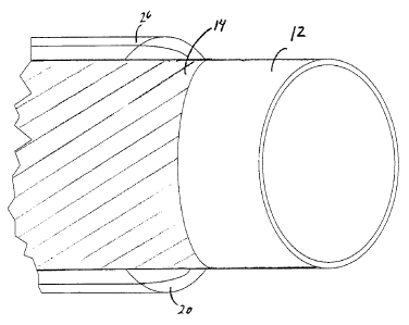
[00093] As shown in Figures 2 and 3, in an embodiment of the invention, the
insulated pipe may further comprise a first bonding layer 14 applied to an
CA 02555756 2006-08-10
- 16-
exterior surface of the pipe 12 to be insulated for securing the composite
insulation system to the pipe.
[00094] In another embodiment of the invention, the composite thermal
insulation system may further comprise a first reinforcement layer 18 disposed
over the first insulation layer 16.
[00095] In a further embodiment of the invention, the composite thermal
insulation system may further comprise a second reinforcement layer 22
disposed over the second insulation layer 20.
[00096] In a further embodiment of the invention, the composite thermal
insulation system may further comprise a second bonding layer 24 disposed over
either over the second insulation layer 20 or the second reinforcement layer
22 if
present.
[00097] In a further embodiment of the invention, the composite thermal
insulation system may further comprise an outer jacket 26 disposed over the
second insulation layer 20 or the second bonding layer 24 if present.
[00098] The insulated pipe according to the invention may be adapted for
subsea applications. It is necessary that subsea pipelines have not only a
good
heat insulation but also protection against mechanical damage due to exposure
to hydrostatic pressures and water penetration in order to prevent corrosion.
Inclusion of an outer jacket which is resistant to water ingress and ambient
pressures can be used to provide protection to the insulated pipe.
[00099] In another aspect, the present invention provides an insulated pipe
for use in an undersea pipeline, comprising: a pipe; a composite insulation
system and an outer jacket. The composite insulation system comprises: (a) a
first insulation layer comprising a first insulation material having a thermal
conductivity k-factor value of less than 0.023 W/m-K at 38 C and (b) at least
one additional insulation layer comprising an insulation material having a
thermal
conductivity k-factor greater than that of the first insulation material and a
maximum operating temperature limit less than that of the first insulation
layer.
The composite insulation system is applied to an exterior surface of said pipe
CA 02555756 2006-08-10
- 17-
with the first insulation layer facing towards said exterior surface of said
pipe. At
least one of said first insulation layer or said at least one additional layer
extends
continuously about said exterior surface of the pipe. The outer jacket covers
the
composite insulation system, protecting the composite insulation system and
pipe from water ingress and from ambient pressure.
[000100] In an embodiment of the invention, the composite insulation system
is formed by application of the first insulation layer to the exterior surface
of the
pipe followed by application of an additional insulation layer to surround
said first
insulation layer wherein application of one or more of the first insulation
layer or
additional insulation layers is performed in a continuous manner.
[000101] The insulated pipe according to the invention may be adapted for
subterranean applications. Buried pipelines are subject to deterioration due
to
mechanical and chemical damage. Long term exposure to soil stress forces may
causes applied coatings and insulation layers to creep or detach from the pipe
on
which they are applied. The inclusion of at least one or more of a bonding
layer
(such as an adhesive layer) or a reinforcement layer (such as a tape layer)
secures the composite insulation system to the pipe to be insulated and
protects
the resulting insulated pipe from soil stress forces (such as shear). The
inclusion
of an outer jacket which is resistant to water ingress protects both the
insulation
system and the pipe from deterioration and corrosion. The outer jacket may
also
be resistant to soil stress forces to provide further protection of the
insulated
pipe.
[000102] In a further aspect, the present invention provides an insulated pipe
for use in a subterranean pipeline, comprising: a pipe; a composite insulation
system, at least one of a bonding layer or reinforcement layer, and an outer
jacket. The composite insulation system comprises: (a) a first insulation
layer
comprising a first insulation material having a thermal conductivity k-factor
value
of less than 0.023 W/m-K at 38 C; and (b) at least one additional insulation
layer comprising an insulation material having a thermal conductivity k-factor
greater than that of the first insulation material and a maximum operating
temperature limit less than that of the first insulation layer. The composite
insulation system is applied to an exterior surface of the pipe with the first
CA 02555756 2006-08-10
- 18-
insulation layer facing towards said exterior surface of the pipe. At least
one of
said first insulation layer or said at least one additional layer extends
continuously about said exterior surface of the pipe. At least one of a
bonding
layer and/or reinforcement layer is provided for securing the composite
insulation
system to the pipe. The at least one bonding layer and/or reinforcement layer
protects the composite insulation system from soil stress forces. The outer
jacket covers the composite insulation system and protects the composite
insulation system and pipe from water ingress.
[000103] In an embodiment of the invention, the composite insulation system
is formed by application of the first insulation layer to the exterior surface
of the
pipe followed by application of an additional insulation layer to surround
said first
insulation layer wherein application of one or more of the first insulation
layer or
additional insulation layers is performed in a continuous manner.
[000104] Innermost First Insulation Layer
[000105] The composite insulation system comprises multiple layers of
insulation. Each insulation layer will differ from one another in terms of the
insulation material used to form the individual insulation layers. Each
insulation
layer itself may be comprised of multiple layers of the particular insulation
material. For example, an insulation layer may consist of a laminate of
insulation
materials.
[000106] The composite insulation system comprises at least a first insulation
layer comprising a first insulation material and a second insulation layer
comprising a second insulation material. The composite insulation system is
applied to the pipe to be insulated with the first insulation layer facing
towards
the exterior surface of the pipe to be insulated such that the first
insulation layer
constitute the innermost insulation layer of the composite insulation system.
[000107] As used herein, reference to "innermost insulation layer" and "first
insulation layer" refers to the insulation layer of the composite insulation
system
which faces the closest to the exterior surface of the pipe to be insulated.
CA 02555756 2006-08-10
- 19-
[000108] The innermost insulation layer may be situated in direct contact
with the pipe to be insulated. In some embodiments, it may be desirable to
coat
the exterior surface of the pipe to be insulated with anti-corrosion coatings
and
or other protective coatings known in the art. In other embodiments, it may be
desirable to coat the exterior surface with an adhesive layer to form a
bonding
layer for securing the composite insulation system to the pipe to be
insulated. In
these embodiments, the innermost insulation layer may be applied over the
protective coating or bonding layer (see further discussion below).
[000109] The primary function of the innermost insulation layer is to restrict
heat flow to the second insulation layer, thereby reducing the temperature to
a
level which the second insulation layer can withstand for the required service
life.
The innermost insulation layer therefore comprises materials selected from
materials which are more heat-resistant than those used in the second
insulation
layer, and which have thermal conductivity equal to or lower than that of the
second insulation layer.
[000110] The second insulation layer normally provides much of the overall
resistance to heat flow for the insulated pipe because it is substantially
thicker
than the innermost layer and is itself an excellent insulator. Ideally it is
also
relatively inexpensive in relation to the material used to form the innermost
layer, and is convenient to apply in significant thickness.
[000111] The high efficiency insulation materials used to prepare the
innermost insulation layer will have a k-factor value of equal to or less than
0.023 W/m-K at 38 C as determined in accordance with standard thermal
conductivity test methodologies known in the art, such as ASTM C177, ASTM C
335, ASTM C 518, ASTM C1041 or ASTM C1045. Preferably, the high efficiency
insulation materials have a k-factor of less than 0.02 /m-K at 38 C, more
preferably a k-factor of less than 0.017 W/m-K at 38 C, and even more
preferably a k-factor of less than 0.015 W/m-K at 38 C. In any event, the
first
insulation material will have a k-factor substantially equal to or lower than
the
effective k-factor of the second insulation layer.
[000112] The innermost insulation layer may comprise substantially inorganic
materials or inorganic/organic based materials and in particular,
substantially
CA 02555756 2006-08-10
- 20 -
inorganic based microporous insulation materials and substantially inorganic
based nanoporous insulation materials. Preferably, the substantially inorganic
microporous and nanoporous insulation materials are silica based. Examples of
suitable inorganic insulation materials include, but are not limited to: fumed
silica, microporous silica, inorganic aerogel, and nanoporous silica. These
thermal insulation materials provide very good temperature reductions per unit
of applied thickness compared to traditional materials, such as perlite and
calcium silicate (see Table 1). The first insulation layer, depending on the
choice
of insulation material, may further comprise one or more of: a binder,
reinforcing
fibers, a reinforcing woven fabric or a reinforcing unwoven fabric to provide
structural integrity.
[000113] In a preferred embodiment of the invention, the innermost
insulation layer comprises a silica based aerogel having a k-factor of less
than
0.017 W/m-K at 38 C, and more preferably a silica based aerogel having a k-
factor of less than 0.015 W/m-K at 38 C. Two examples of commercially
available aerogel blankets are listed in Table 1, below.
[000114] The first insulation material may be in the form of a flexible
blanket
or in tape, and may comprise multiple layers thereof.
Table One - Comparison of Thermal Conductivity for Various
Materials
Item Aerogel Aerogel Aerogel Micro- Rock Perlit Calciu PIF
-1 -2 -3 porous wool e m
silica Silicate
Product Spacelof Pyrogel Nanogel Microther Roxul Sproul Thermo ShawCo
Name t 2200 6650 Thermal m Super- 1200 e WR- -12 r HT
Blanket Wrap G Tape 1200 Gold Foam
Bulk 130 120 75 320 140 192 232 60
Density
(kg/m3)
Thermal 0.0135 0.0145 0.021 0.022 0.038 0.069 0.052 0.0253
Conductivit
y at 38 C
(W/m-K)
K-Factor Aspen Aspen Bredero Bredero Roxul Calsilit Calsilite Bredero
Data Aerogels Aerogels Shaw Shaw Inc. e Group Shaw
Source Spacelof Pyrogel Revise Group IIG-300
t 2200 6650 d Dec IIG-
CA 02555756 2006-08-10
- 21 -
Item Aerogel Aerogel Aerogel Micro- Rock Perlit Calciu PIF
-1 -2 -3 porous wool e m
silica Silicate
Rev 1.0 Rev 1.0 21/04 200 2- 2-05
05
[000115] Substantially organic based materials including, but not limited to:
binders, fibers or reinforcing fabrics may also be present or incorporated
into the
material comprising the first insulation layer.
[000116] In preferred embodiments of the invention, the first insulation layer
may comprise a mineral based insulation material such as but not limited to
fumed silica, microporous silica, nanoporous silica, a silica based aerogel
and the
second insulation layer (see further discussion below) may comprise a
polymeric
foam insulation material comprising polyurethane or polyisocyanurate. In a
further preferred embodiment of the invention, the first insulation layer
comprises a silica based aerogel and the second insulation layer comprises a
polymeric foam insulation material comprising polyurethane or
polyisocyanurate.
In such embodiments, the thermal conductivity of the first insulation layer
will be
equal to or lower than that of the second insulation layer, and as such, the
total
insulation thickness will be smaller than what would be obtained using the
second insulation layer by itself, in order to achieve comparable or superior
overall insulation performance. Depending on the particular choice of
insulation
materials, at least one of the first or second insulation layers is formed in
situ in
a continuous manner and in some embodiments, both the first and second
insulation layers are formed in a continuous manner. For example, some
embodiments may be formed by continuous wrapping of the first insulation layer
(for example, an aerogel blanket) onto the pipe followed by continuous
spraying
of polymeric foam insulation over the first insulation layer.
[000117] Second Insulation Layer
[000118] The second insulation layer will be of a composition that it cannot
by
itself, withstand the operating temperature of the pipe to be insulated for
the
expected service life of the pipe. In addition, the thermal conductivity of
the
second layer, or the effective k-factor in the case of the second insulation
layer
CA 02555756 2006-08-10
- 22 -
comprising multiple layers, will be equal to or higher than that of the first
insulation layer.
[000119] The second insulation layer may be bonded directly to the first
insulation layer. In some embodiments, the first and second insulation layers
may be separated by a first reinforcement layer.
[000120] The second insulation layer may comprise substantially organic
based insulation materials or substantially inorganic based insulation
materials.
Suitable organic insulating materials may include, but are not limited to:
polyurethane foams, polyisocyanurate foams, thermoplastic foams (for example,
expanded polyethylene, or polypropylene, polystyrene, etc). The organic foam
may be blown foam or syntactic foam.
[000121] In a preferred embodiment, the second insulation layer may
comprise a polymeric foam and more preferably polyurethane foam,
polyisocyanurate foam or phenolic foam.
[000122] In another preferred embodiment, the second insulation layer may
comprise a thermoplastic foam, and more preferably, a thermoplastic foam
comprising polyethylene, polypropylene, or polystyrene binder.
[000123] In a further preferred embodiment, the second insulation layer may
comprise a syntactic polymeric foam comprising polyurethane, polyisocyanurate,
epoxy or phenolic binder. The syntactic polymeric foam may also comprise
polypropylene or polystyrene binder.
[000124] In particularly preferred embodiments, materials for the second
insulation layer are rigid closed cell polyurethane, polyisocyanurate,
poly(urethane-isocyanurate), or phenolic foams. The higher the operating
temperature capability of the second insulation layer, the thinner the
innermost
layer can be.
[000125] The second insulation layer may be applied onto first inner
insulation layer or the reinforcement layer if employed, by a variety of
processes
known in the art such as: molding, pouring, injection, spraying, casting, etc,
or
CA 02555756 2006-08-10
-23-
as pre-formed pieces (i.e., "shells). The preferred method of application will
depend on the particular choice of insulation material.
[000126] Securing or Bonding Layers
[000127] In some embodiments of the invention, means for securing the
composite insulation system to the pipe may be provided. A first bonding layer
may be provided for securing the composite insulation system to the pipe
wherein the first bonding layer is disposed between the first insulation
system
and the exterior surface of the pipe. In such embodiments, the securing may
take the form of adhesive bonding. In addition to containing an adhesive, the
first bonding layer may comprise an anti-corrosion agent, a primer or
combinations thereof depending on the intended application of the insulated
pipe
as discussed in further detail below.
[000128] In another embodiment, the composite insulation system may be
secured to the pipe by applying a reinforcing layer, such as a fibrous
material or
adhesive tape which is wrapped around the outer circumference of the layer to
be secured.
[000129] The purpose of securing the composite insulation system to the pipe
is to prevent the innermost insulation layer from moving in relation to the
pipe,
and to prevent the various insulation layers from moving in relation to one
another. Typical driving forces for such relative movement are differential
thermal expansion of the components or expansion and contraction of the soil
if
the pipe is buried.
[000130] For certain applications, a bonding or adhesive layer may also serve
as a corrosion resistant barrier to protect the pipe from the potentially
corrosive
effects of moisture vapor or water ingress or other agents into the coating
system. This would be applied to the outer surface of the pipe prior to the
installation of the innermost insulation layer, which would be applied while
the
bonding layer is still able to form a bond to it. Alternatively, the pipe
might be
provided with a fully functional anti-corrosion coating already applied, in
which
case the bonding or adhesive layer may be applied either to the coated pipe or
CA 02555756 2006-08-10
- 24-
the interior surface of the innermost insulation layer just prior to bringing
the
two into contact.
[000131] Materials suitable for use as the bonding layers include, but are not
restricted to, epoxy based adhesives and coatings, silicone based adhesives
and
coatings, polyurethane based adhesives, cementitious or ceramic based mortars
and adhesives, hydraulic cement based adhesives, heat-activated thermoplastic
or thermoset adhesives or other common adhesive materials.
[000132] In further embodiments of the invention a second bonding or
adhesive layer may be required to bond the second insulation layer to the
outer
jacket. The second bonding layer may comprise any of the adhesives referred to
above
[000133] In embodiments of the invention, wherein the second insulation
layer comprises expanded polymeric foam and an extruded polymeric outer
jacket, the second bonding or adhesive layer is preferably an adhesive
material
based on asphalt modifed rubber chemistry.
[000134] Reinforcement Layers
[000135] In some embodiments of the invention, a first reinforcement layer
may be provided and disposed between the first insulation layer and the second
insulation layer. In cases where it is desirable to reinforce or secure the
first
insulation layer to the pipe by physical means rather than adhesively, the
first
reinforcement layer must be capable of withstanding the temperature it will
encounter in service. Materials suitable for such application comprise, but
are not
restricted to, organic or inorganic based materials, such as woven and unwoven
fabrics of heat-resistant materials such as glass fiber, steel, ceramic,
carbon
fibers, polyester, and high temperature resistant polymers.
[000136] In embodiments wherein the first insulation layer comprises for
example an aerogel blanket material, it may be desirable to apply a
reinforcing
mesh of non-woven materials, such as a scrim, to compress the aerogel blanket
material, thereby improving the thermal insulation value of the aerogel
blanket
material by removing trapped air and reducing its physical thickness. The use
of
CA 02555756 2006-08-10
- 25 -
such a scrim also produces a smoother surface onto which the second insulation
layer can be either spray applied or molded especially in the embodiments
wherein the second insulation layer comprises PUF/PIR foam insulation. The
scrim may be constructed of organic or inorganic (e.g. glass fiber) materials
depending on the service temperature required, and is of an open mesh
construction allowing the foam insulation to penetrate it and bond directly
onto
the underlying insulation material. This also allows the foam to encapsulate
the
scrim securing it in place. In some cases, the scrim material may not be
required to be used if the insulation material of the first insulation layer
is
provided preformed, such as Microtherm Super G tape, or other equivalents
known in the art.
[000137] The first reinforcement layer may be either pre-applied to the first
insulation material prior to product assembly or may be separately applied
once
the first insulation layer is applied onto the pipe. The reinforcement layer
may
serve various purposes such as: (1) preventing damage to the inner layer
during
processing and product handling; (2) compressing or reinforcing the inner
layer
for retention or improvement of insulating value as well as to assist in
maintaining the structural integrity of the system during manufacturing or in-
service conditions; and (3) provides an additional anchor surface for the
subsequently applied organic insulation, reducing the likelihood of loss of
adhesion or delamination at the interface of the two materials during
manufacturing or in-service conditions.
[000138] In some embodiments of the invention, it may be desirable to
include a second reinforcement layer disposed over the second insulation layer
to
secure or reinforce the second insulation layer. The second reinforcement
layer
may comprise a tape layer or an equivalent wrap applied product. Polymeric
based tapes are well known in the art. The use of a tape layer is particularly
preferred in embodiments of the invention, wherein the second insulation layer
comprises a polymeric insulating foam such as polyurethane or polyisocyanurate
foam. The tape layer may be employed to reinforce the polymeric foam by
providing additional mechanical protection or for securing an optional outer
jacket to the second insulation layer. The use of a tape layer is particularly
preferred in circumstances wherein the pipe to be thermally insulated is of
large
CA 02555756 2006-08-10
-26-
diameter or has heavy walls or in other circumstances where additional
protection is required.
[000139] Outer Jacket
[000140] In some embodiments of the invention, it may be desirable to
include an outer jacket. The outer jacket may serve to protect the insulation
system from potential ingress of moisture, physical damage (i.e. resulting
from
exposure to soil stress) and also in some cases, the loss of the insulating
blowing
agents from certain polymeric foams used for the secondary insulation layer.
[000141] In a preferred embodiment, the outer jacket is resistant to water
ingress and is particularly suited for use with pipes intended for subsea or
subterranean application. In another embodiment, the outer jacket is may also
be resistant to soil stress forces such as shear forces, and is particularly
suited
for subterranean application. Watertight polymeric coverings and watertight
pipes (i.e. casings) are particularly suitable for use in subsea or
subterranean
environments.
[000142] The outer jacket may be comprised of polymeric materials
including: polyethylene, polypropylene, nylon (such as nylon 11, nylon 12),
polyurethane, polyurea or other suitable materials, of metallic materials such
as
steel, aluminum which may be optionally coated with an anticorrosion coating
or,
of composite materials such as fiber-reinforced resins or reinforced thermoset
polymeric materials containing reinforcing materials such as glass fibers,
mica, or
other reinforcing materials. The jacket may also comprise unreinforced
elastomeric coatings applied initially in liquid form and subsequently
converted to
solids by chemical reaction. Examples of such coatings include urethane
elastomers, polyureas and epoxy coatings.
[000143] In a preferred embodiment, the outer jacket is an extruded
polymeric jacket or covering comprising an extruded polyolefin, extruded
polyamide, or an extruded elastomer. More preferably the outer jacket is an
extruded high density polyethylene or an extruded polypropylene jacket. For
polyethylene or polypropylene jackets, the materials can be applied onto the
insulated pipe by either crosshead or side-wrap extrusion processes. In
another
CA 02555756 2006-08-10
- 27-
preferred embodiment, the polymeric jacket or covering comprising a thermoset
polymeric material such as but not limited to polyurethane or an epoxy. The
polymeric jacket and covering is preferably watertight when used with
insulated
pipes intended for subseas or subterranean applications.
[000144] For certain molded foam based systems, the jacket may be in the
form of a pre-manufactured plastic or metallic pipe (i.e. casing). In such
embodiments, the innermost insulation layer is first attached to the pipe, and
this assembly is inserted and centered in the casing. The second insulation
layer
is then applied by introducing the mixed components into the annular space and
allowing the foam to rise and cure.
[000145] Although the invention has been described with reference to
illustrative embodiments, it is to be understood that the invention is not
limited
to these precise embodiments, and that various changes and modification are to
be intended to be encompassed in the appended claims.