Note: Descriptions are shown in the official language in which they were submitted.
CA 02555952 2006-08-11
WO 2005/082216 PCT/US2005/000610
IN T.HE UNITED STATES PATENT AND TRADEMARK OFFICE
Patent Application
for
SPRAYLESS SURFACE CLEANER
Inventor(s): Roy Studebaker, a United States citizen
residing in: Centralia, Lewis County, Washington State, USA
FIELD OF THE INVENTION
The present invention to a tool for cleaning surfaces, and in particular to an
apparatus and method of delivering cleaning fluid for cleaning flooring
surfaces, wall
surfaces and upholstery.
BACKGROUND OF THE INVENTION
Many apparatuses and methods are known for cleaning carpeting and other
flooring, wall and upholstery surfaces. The cleaning apparatuses and methods
most
commonly used today apply cleaning fluid as a spray under pressure to the
surface
whereupon the cleaning fluid dissolves the dirt and stains and the apparatus
scrubs the fibers
while simultaneously applying a vacuum or negative pressure to extract the
cleaning fluid
and the dissolved soil. Although such relatively high pressure methods are the
most
commonly used, they have disadvantages. First, the majority of the soil is at
or near the
surface of the fibers so that high pressure cleaning tends to drive same of
the surface soil and
cleaning fluid deeper, whereby a very powerful vacuum system is required to
extract
particles that have been driven beneath the outermost surface. Furthermore,
the use of
cleaning fluid under pressure, applied as a spray through conventional jets,
drives the fluid
itself deeper, and the fluid that is not immediately removed by the vacuum
source requires a
significantly longer drying period. While longer drying time is an
inconvenience, if the
carpeting is used prior to its being completely dry, it is more likely to
become soiled.
Additionally, conventional jets atomize the sprayed fluid which then comes
into contact with
the air, causing significant heat loss and diminishing the cleaning power of
the fluid.
CA 02555952 2006-08-11
WO 2005/082216 PCT/US2005/000610
Many different apparatuses and methods for spraying cleaning fluid under
pressure and then removing it with a vacuum are illustrated in the prior art
supplied herewith
but will not be discussed in detail.
Another category of carpeting and upholstery cleaning apparatuses and
methods use a rotating device wherein the entire machine is transported over
the carpeting
while a cleaning head is rotated about a vertical axis. Typically, these
machines include a
plurality of arms, each of having one or more spray nozzles or a vacuum source
providing a
more intense scrubbing action since, in general, more scrubbing surfaces
contact the carpet.
These apparatuses and methods are primarily illustrated in U. S. Pat. No.
4,441,229 granted
to Monson on April 10, 1984, and are listed in the prior art known to the
inventor but not
discussed in detail herein.
A third category of carpeting and upholstery cleaning apparatuses and
methods that attempt to deflect or otherwise control the cleaning fluid are
illustrated by U.S.
Pat. No. 4,137,600 granted to Albishausen on February 6, 1970, which discloses
a cleaning
apparatus wherein the cleaning fluid is changed into a liquid curtain by a
baffle within the
cleaning head; U.S. Pat. No. 4,335,486 granted to Kochte on January 22, 1982,
which
discloses a surface cleaning machine wherein the cleaning fluid is deposited
upon the surface
of the carpet pile from a wick like device wetted with the cleaning fluid; U.
S. Pat. No.
4,649,594 granted to Grave on Mar. 17, 1987, which discloses a cleaning head
wherein the
cleaning solution is sprayed through a narrow passage and some is wicked along
the surface
of the passage; U. S. Pat. No. 5,157,805 granted to Pinter on Oct. 27, 1992,
which discloses a
method and apparatus for cleaning a carpet wherein the cleaning fluid is
sprayed by nozzle
against the back of a striker plate and then flows downwardly and through the
carpet to a
pickup vacuum; and U.S. Pat. No. 5,561,884 granted to Nijland et al on Oct. 8,
1996, which
discloses a suction attachment spray member wherein the fluid is sprayed
against a
distributor plate that creates a planar diverging liquid jet substantially
filling the vacuum
chamber.
U.S. Pat. No. 6,243,914, which was granted June 12, 2001, to the inventor of
the present patent application and which is incorporated herein by reference,
discloses a
cleaning head for carpets, walls or upholstery, having a rigid open-bottomed
main body that
defines a surface subjected to the cleaning process. Mounted within or
adjacent to the main
body and coplanar with the bottom thereof is a fluid-applying device which
includes a slot at
2
CA 02555952 2006-08-11
WO 2005/082216 PCT/US2005/000610
an acute angle to the plane of the bottom of the body located adjacent the
plane of the bottom
of the body, the slot configured such that the fluid is applied in a thin
sheet that flows out of
the slot and into the upper portion of the surface to be cleaned and
subsequently into the
vacuum source for recovery. The cleaning head is alternatively multiply
embodied in a
plurality of arms which are rotated about a hub.
Figure 1 is a cross-sectional view that illustrates one of four separate
embodiments of the cleaning head disclosed in U. S. Pat. No. 6,243,914 wherein
the cleaning
head 1 for applying cleaning fluid without the inherent problems of spray
either escaping or
unduly penetrating the carpeting. Front and back surfaces 3, 5 of the cleaning
head 1
combine with opposing end panels (not shown) to define a rectangular lip 7
which defines a
surface contact area of the surface to be cleaned, which is momentarily
subjected to the
cleaning environment generated by the cleaning head 1. Securely mounted to an
interior
portion of the cleaning head 1 is a downwardly open fluid supply chamber 9
formed between
a first wall 11 terminating in a head surface 13 and a second wall 15
terminating in an
inwardly turned foot 17. The fluid supply chamber 9 terminates in an angled
slot or groove
19 adjacent to the head surface 13 and oriented at an obtuse angle thereto,
i.e., an acute angle
to the surface to be cleaned. Walls 21 and 23 combine with opposing end panels
(not shown)
to form a vacuum chamber 25 that is spaced away from the fluid supply chamber
9 by the
width of the head surface 13.
As disclosed in U.S. Pat. No. 6,243,914, cleaning fluid is supplied in a
steady
stream downwardly through the fluid supply chamber 9 between the walls l 1 and
15 and
flows outwardly through the angled slot 19 past the foot 17 and is drawn in a
sheet across the
head surface 13 by a vacuum formed in the vacuum chamber 25, whereby it is
applied
uniformly to the carpeting or other surface to be cleaned. The fluid is
removed from the
cleaned surface by vacuum in the vacuum chamber 25. The utilization of a sheet
of fluid
which flows down the fluid supply chamber 9 and across the head surface 13
eliminates the
cooling of the fluid that results from atomizing caused by prior art spray
nozzles. The
utilization of a sheet of fluid also reduces the amount of fluid being used
for a given cleaning
job, and eliminates over spray of the cleaning fluid should the cleaning head
1 be
inadvertently moved from the surface to be cleaned or tilted so one edge is
raised.
The present invention provides improvements to the cleaning head disclosed
in U.S. Pat. No. 6,243,914.
CA 02555952 2006-08-11
WO 2005/082216 PCT/US2005/000610
SUMMARY OF THE INVENTION
The present invention provides novel improvements on the cleaning head
disclosed in U.S. Pat. No. 6,243,914. Accordingly, the present invention
provides an
improved apparatus and method for spraylessly delivering cleaning fluid for
cleaning
flooring surfaces, wall surfaces and upholstery.
According to one aspect of the invention, the apparatus and method of the
invention is embodied in a novel three-part bar jet assembly formed of a
substantially flat
base plate having spaced apart and substantially parallel planar cleaning
fluid input and
output surfaces and an elongated cleaning fluid discharge chamber formed
therein in
communication with both the input and output surfaces, the discharge chamber
having a
relatively long and wide mouth or opening in communication with the fluid
input surface
and terminating adjacent to one side of the chamber in a relatively shorter
and narrower
discharge slot that is in communication with the fluid output surface; a
forward or leading
cover plate having spaced apart and substantially parallel planar mounting and
cleaning fluid
output surfaces that are interconnected along one edge by a substantially
planar cleaning
fluid retrieval slot surface that is oriented to form a right angle with both
the mounting and
output surfaces and along an opposite edge by a substantially planar discharge
slot leading
surface that is optionally oriented to form an obtuse angle to the leading
cover plate output
surface, the mounting surface of the leading cover plate is securely fixed to
the output
surface of the base plate with the discharge slot leading surface adjacent to
and substantially
contiguous with an edge of the base plate discharge slot opposite from the
discharge
chamber of the base plate and the retrieval slot surface adjacent to and
substantially
contiguous with a substantially planar right-angled peripheral edge surface of
the base plate;
and an aft or following cover plate having spaced apart and substantially
parallel planar
mounting and cleaning fluid output surfaces that are interconnected along one
edge by a
substantially planar discharge slot following surface that is optionally
oriented to form an
acute angle to the following cover plate output surface, the mounting surface
of the
following cover plate is securely fixed to the output surface of the base
plate with the
discharge slot following surface adjacent to and substantially contiguous with
an edge of the
base plate discharge slot opposite from the leading cover plate and spaced
away from the
discharge slot leading surface, whereby the spaced apart discharge slot
leading and following
4
CA 02555952 2006-08-11
WO 2005/082216 PCT/US2005/000610
surfaces form therebetween a narrow cleaning fluid discharge slot oriented at
an acute angle
to the cleaning fluid output surfaces of the leading and following cover
plates.
According to another aspect of the invention, the invention is embodied in a
cleaning head having the bar jet assembly of the invention being coupled to a
nozzle, the
nozzle being structured for coupling a source of pressurized cleaning fluid to
the bar jet
assembly cleaning fluid discharge chamber, and being further structured for
coupling a
vacuum source in communication with the bar jet assembly cleaning fluid
retrieval slot
surface.
According to another aspect of the invention, the cleaning head is a rotary
cleaning head that is structured to be rotated by a motor, by example and
without limitation,
either directly or via a gear or belt drive.
According to another aspect of the invention, the present invention provides a
method for cleaning a surface.
BRIEF DESCRIPTION OF THE DRAWINGS
I 5 The foregoing aspects and many of the attendant advantages of this
invention
will become more readily appreciated as the same becomes better understood by
reference to
the following detailed description, when taken in conjunction with the
accompanying
drawings, wherein:
Figure 1 is a cross-sectional view that illustrates one of four separate
embodiments of the cleaning head disclosed in U. S. Pat. No. 6,243,914;
Figure 2 is an exemplary illustration of a cleaning system useful for
operating
the improved cleaning head of the present invention;
Figure 3 is a cross-sectional view of the cleaning head of the invention taken
through the plan view of Figure 4.
Figure 4 is a top down or plan view of the cleaning head of the invention that
illustrates the distributed flow channels of the cleaning fluid;
Figure 5 is a bottom plan view of the cleaning surface of a rotary cleaning
plate of the invention having a plurality of bar jet assemblies of the
invention and stabilizers
fixed thereto in a uniformly distributed manner;
Figures 6, 7, 8 and 9 illustrate one embodiment of the bar jet assembly of the
invention, wherein Figure 6 is a top plan view looking at a cleaning fluid
input face of the
5
CA 02555952 2006-08-11
WO 2005/082216 PCT/US2005/000610
bar jet assembly, Figure 7 is an end view taken from Figure 6, Figure 8 is a
cross-sectional
view taken through the top plan view of Figure 6, and Figure 9 is a bottom
plan view looking
at the operational cleaning face of the bar jet assembly of the invention;
Figure 10 is a plan view of a shoe member in which the bar jet assembly of
the invention is optionally embedded or otherwise supported;
Figures l l and 12 are top and bottom plan views, respectively, of a base
plate
portion of the bar jet assembly of the invention;
Figures 13 and 14 are plan and end views, respectively, of a forward or
leading cover plate embodiment of the cleaning head surface of the invention;
Figures 15 and 16 are plan and end views, respectively, of an aft or following
cover plate embodiment of the cleaning head surface of the invention;
Figure 17 illustrates one alternative embodiment of the invention wherein the
cleaning head of the invention incorporates a single bar jet assembly of the
invention in a
hand-held nozzle;
Figures 18, 19 and 20 illustrate one alternative embodiment of the bar jet
assembly of the invention, wherein Figure 18 is a top plan view looking at the
cleaning fluid
input face of the alternative bar jet assembly, Figure 19 is a bottom plan
view looking at the
operational cleaning face of the alternative bar jet assembly, and Figure 19
is a
cross-sectional view of the alternative bar jet assembly taken through the top
plan view of
Figure 18;
Figures 21 and 22 are end views, respectively, of the forward or leading cover
plate and the aft or following cover plate according to the alternative
embodiment of the
invention illustrated in Figures 18, 19, 20;
Figures 23, 24, 25 and 26 illustrate another alternative embodiment of the bar
jet assembly of the invention, wherein Figure 23 is a top plan view looking at
the cleaning
fluid input face of the alternative bar jet assembly, Figure 24 is a bottom
plan view looking
at the operational cleaning face of the alternative bar jet assembly, and
Figures 25 and 26 are
alternative cross-sectional views of the alternative bar jet assembly taken
through the top
plan view of Figure 23; and
Figures 27, 28, 29 and 30 illustrate another alternative embodiment of the bar
jet assembly of the invention, wherein Figure 27 is a top plan view looking at
the cleaning
fluid input face of the alternative bar jet assembly, Figure 28 is a bottom
plan view looking
6
CA 02555952 2006-08-11
WO 2005/082216 PCT/US2005/000610
at the operational cleaning face of the alternative bar jet assembly, and
Figures 29 and 30 are
alternative cross-sectional views of the alternative bar jet assembly taken
through the top
plan view of Figure 27.
DETAILED DESCRIPTION OF PREFERRED EMBODIMENT
In the Figures, like numerals indicate like elements.
The present invention is an apparatus and method for spraylessly delivering
cleaning fluid for cleaning flooring surfaces, wall surfaces and upholstery.
The apparatus and
method of the invention being embodied, by example and without limitation, in
a novel
three-part bar jet assembly formed of a substantially flat base plate having
spaced apart and
substantially parallel planar cleaning fluid input and output surfaces and
having an elongated
cleaning fluid discharge chamber formed therein in communication with both the
input and
output surfaces, the discharge chamber having a relatively long and wide mouth
or opening
in communication with the fluid input surface and terminating adjacent to one
side of the
chamber in a relatively shorter and narrower discharge slot that is in
communication with the
fluid output surface; a forward or leading cover plate having spaced apart and
substantially
parallel planar mounting and cleaning fluid output surfaces that are
interconnected along one
edge by a substantially planar cleaning fluid retrieval slot surface that is
oriented to form a
right angle with both the mounting and output surfaces and along an opposite
edge by a
substantially planar discharge orifice leading surface that is optionally
oriented to form an
obtuse angle to the leading cover plate output surface, the mounting surface
of the leading
cover plate is securely fixed to the output surface of the base plate with the
discharge orifice
leading surface adjacent to and substantially contiguous with an edge of the
base plate
discharge orifice opposite from the discharge chamber of the base plate and
the retrieval slot
surface adjacent to and substantially contiguous with a substantially planar
right-angled
peripheral edge surface of the base plate; and an aft or following cover plate
having spaced
apart and substantially parallel planar mounting and cleaning fluid output
surfaces that are
interconnected along one edge by a substantially planar discharge orifice
following surface
that is optionally oriented to form the same acute angle to the following
cover plate output
surface, the mounting surface of the following cover plate is securely fixed
to the output
surface of the base plate with the discharge orifice following surface
adjacent to and
substantially contiguous with an edge of the base plate discharge slot
opposite from the
7
CA 02555952 2006-08-11
WO 2005/082216 PCT/US2005/000610
leading cover plate and spaced away from the discharge orifice leading
surface, whereby the
spaced apart discharge orifice leading and following surfaces form
therebetween a narrow
and elongated cleaning fluid discharge slot oriented at an acute angle to the
cleaning fluid
output surfaces of the leading and following cover plates.
According to one embodiment of the invention, the acute angle formed by the
narrow cleaning fluid discharge slot relative to the cleaning fluid output
surfaces of the
leading and following cover plates is on the order of 45 degrees or less.
Furthermore, the
discharge orifice leading and following surfaces are spaced apart by 0.020
inches or less to
form the narrow and elongated cleaning fluid discharge slot.
According to one embodiment ofthe invention, the cleaning fluid discharge
chamber is formed in the base plate having a striker plate adjacent to the
discharge slot. By
example and without limitation, the striker plate is embodied as a
substantially planar
surface having one elongated edge that intersects the cleaning fluid input
surface of the base
plate and a second elongated edge that intersects one side of the discharge
slot adjacent to
the fluid output surface. An elongated upright wall portion of the fluid
discharge chamber is
formed between the cleaning fluid input surface of the base plate and the
other side of the
discharge slot opposite from the striker plate. According to one embodiment of
the
invention, the upright wall is oriented substantially at a right angle to the
cleaning fluid input
surface of the base plate, whereby the fluid discharge chamber is embodied in
an elongated
right triangular chamber having the upright right-angle wall between the base
plate input and
output surfaces on one side of the discharge slot, and the angled striker
plate inclined
between the base plate input and output surfaces on the other side of the
discharge slot
opposite from the upright right-angle wall.
According to one embodiment of the invention, the discharge slot in the base
plate is embodied in an elongated throat situated between the upright right-
angle wall and
the inclined striker plate surface, and communicating between the discharge
chamber and the
output surface of the base plate.
According to one embodiment of the invention, the novel bar jet assembly of
the invention is coupled to a cleaning surface of a rotary cleaning plate
having a cleaning
fluid and soil retrieval slot machined therethrough and being coupled to a
vacuum source,
the right-angled peripheral edge surface of the base plate and the retrieval
slot surface of the
leading cover plate both being positioned adjacent to and substantially
contiguous with the
CA 02555952 2006-08-11
WO 2005/082216 PCT/US2005/000610
retrieval slot machined in the rotary cleaning plate. Additionally, the
relatively long and
wide input opening of the discharge chamber is coupled through the rotary
cleaning plate to
a source of pressurized cleaning fluid. According to one embodiment of the
invention, the
discharge chamber is coupled to a cleaning fluid distribution manifold that is
further
structured to operate as an expansion chamber for reducing the pressure of the
cleaning fluid
to below a delivery pressure provided by the source of pressurized cleaning
fluid.
According to one embodiment of the invention, the rotary cleaning plate
includes a plurality of the cleaning fluid and soil retrieval slots machined
therethrough and
being coupled to the same or another vacuum source, and including a plurality
of the novel
bar jet assemblies with one of the bar jet assemblies being coupled to the
rotary cleaning
plate adjacent to each of the cleaning fluid and soil retrieval slots. By
example and without
limitation, three of the cleaning fluid and soil retrieval slots and bar jet
assemblies
combinations are provided. According to one embodiment of the invention, a
plurality of
stabilizing members is distributed across the cleaning surface of the rotary
cleaning plate
with at least one of the stabilizer members positioned midway between each
pair of the bar
jet assemblies, whereby the cleaning surface of the rotary cleaning plate is
maintained at a
substantially constant and uniform height above or away from the carpeting or
other surface
to be cleaned.
According to one embodiment of the invention, cleaning fluid distribution
manifold includes a centrally located input spree hole and expansion chamber
coupled to a
network of cleaning fluid distribution channels of combined area suff=iciently
enlarged
relative to a cleaning fluid delivery tube as to significantly reduce the
delivery pressure of
the cleaning fluid at the input spree hole to the expansion chamber.
Accordingly, Figure 2 is an exemplary illustration of a cleaning system 100
useful for operating the improved cleaning head of the present invention. The
cleaning
system 100 is, for example, embodied in a main waste receptacle 102 into which
soiled fluid
is returned via a vacuum hose 104 interconnected with the cleaning head 106 of
the
invention. Mounted above the waste receptacle 102 is a vacuum source and
supply of a
pressurized liquid cleaning fluid depicted generally at 108. The liquid
cleaning fluid is
supplied to the cleaning head 106 via a liquid cleaning fluid delivery tube
110 coupled to the
source of pressurized liquid cleaning fluid. It is to be understood that this
cleaning system
could be track-mounted.
9
CA 02555952 2006-08-11
WO 2005/082216 PCT/US2005/000610
Figure 3 is a cross-sectional view of the cleaning head 106 taken through the
plan view of Figure 4. The cleaning head includes a half funnel shaped liquid
cleaning fluid
discharge chamber 112 that is structured to be coupled to the cleaning system
supply of
cleaning fluid via a liquid cleaning fluid delivery slot 113, as discussed
herein. The cleaning
fluid discharge chamber 112 terminates in a parallel or an angled (shown)
striker plate 114
that is adjacent to a perpendicular or an angled (shown) liquid cleaning fluid
discharge slot
or groove 116 opening onto one side of a cleaning head operating surface 118.
Spaced away
from the angled discharge orifice 116 across the expanse of the head operating
surface 118 is
a liquid cleaning fluid and soil retrieval slot retrieval slot or groove 120
coupled to a vacuum
chamber 121 that is structured to be coupled to the cleaning system vacuum
source. The
cleaning fluid and soil retrieval slot 120 is formed in part by a liquid
cleaning fluid retrieval
slot surface 123 that is oriented crosswise to the cleaning head operating
surface 118.
In operation, by means discussed in detail below, the cleaning fluid enters
the
discharge chamber 112 in the cleaning head 106 in a steady stream and impacts
against the
angled striker plate 114 adjacent to the discharge orifice 116. Impact against
the angled
striker plate 114 forms the cleaning fluid into a substantially uniform thin
sheet that flows
out of the discharge chamber 112 onto the cleaning head operating surface 118
through the
angled discharge orifice 116. As indicated by the arrow, the substantially
uniform thin sheet
of cleaning fluid is drawn across the operating surface 118 and into the
retrieval slot 120 and
vacuum chamber 121 by a vacuum formed therein for delivery to the waste
receptacle 102
via the vacuum hose 104.
As described in detail herein, according to the present invention, the
cleaning
fluid discharge chamber 112, the angled striker plate 114 and discharge slot
or groove 116,
and the operating surface 118 are embodied in a bar jet assembly 122 that is
structured for
substantially permanent attachment to a bottom cleaning surface of a
substantially circular
rotary cleaning plate 124 that is coupled for high speed rotary motion
relative to the cleaning
head 106. The bar jet assembly 122 is optionally embedded or otherwise
supported by a shoe
126, shown more clearly in a subsequent Figure, that has about the same
thickness as the bar
jet assembly 122 and is fixed to the surface of the cleaning plate in a manner
that provides a
lead-in for protecting the carpeting or other surface to be cleaned from
damage by impact
with the leading edge of the bar jet assembly 122. Alternatively, one or more
of the parts
making up the bar jet assembly 122 is modified to include the lead-in feature.
The rotary
CA 02555952 2006-08-11
WO 2005/082216 PCT/US2005/000610
cleaning plate 124 includes the retrieval slot 120 which is machined
therethrough and is
positioned adjacent a forward edge of the cleaning head operating surface 118
opposite from
the discharge orifice 116, where the forward edge is leading when the rotary
cleaning plate
124 rotates about its center in the direction that the thin sheet of cleaning
fluid is drawn
across the operating surface 118, as indicated by the arrow and by the
rotational arrow
shown in Figure 5.
According to one embodiment of the invention and illustrated in greater detail
in a subsequent Figure, the bar jet assembly 122 is repeated in a plurality of
bar jet
assemblies 122 distributed evenly across the bottom cleaning surface of the
cleaning plate
124. Optionally, the plurality of distributed bar jet assemblies 122 are
optionally interspersed
with one or more stabilizers 128 also having the lead-in feature described
herein. The
stabilizers 128 are, by example and without limitation, formed of a slick
nylon or Teflon
material to better slide without sticking across the surface to be cleaned.
Figure 4 is a top down or plan view of the cleaning head 106 of the invention
that illustrates the distributed flow channels of the liquid cleaning fluid
into a central sprue
hole 130 and expansion chamber 131 in a liquid cleaning fluid distribution
manifold 132 and
thence outward along closed liquid cleaning fluid distribution channels 134,
the expansion
chamber 131 and cleaning fluid distribution channels 134 being of
substantially greater area
than an inlet which causes the distribution manifold 132 to further operate as
an expansion
chamber for reducing the pressure of the cleaning fluid to below the delivery
pressure
provided by the pressurized source 108. Optionally, another portion of the
cleaning head 106
operates as the expansion chamber without limiting the scope of the invention
as such
devices are well-known in the art. The cleaning fluid is delivered under
reduced pressure to
each of the plurality of bar jet assembly 122 positioned at the outermost
radial extent of the
different cleaning fluid flow distribution channels 134 adjacent to the
periphery of the rotary
cleaning plate 124. The cleaning fluid flow distribution channels 134 are
formed in
communication with the cleaning fluid delivery slot 113 opening in the rotary
cleaning plate
124 positioned at least adjacent to and preferably contiguous with or
overlapping the
cleaning fluid discharge chamber 112 of the corresponding bar jet assembly 122
such that
the cleaning fluid naturally enters the discharge chamber 112 through the
delivery slot 113.
Figure 5 is a bottom plan view of the cleaning surface of the rotary cleaning
plate 124 having a plurality of the bar jet assemblies 122 and the stabilizers
128 fixed thereto
11
CA 02555952 2006-08-11
WO 2005/082216 PCT/US2005/000610
in a uniformly distributed manner with each of the bar jet assemblies 122
being embedded in
one of the shoes 126. By example and without limitation, the bar jet
assemblies 122 and
stabilizers 128 are each fixed to the cleaning surface of the rotary cleaning
plate 124 by one
or more threaded fasteners 136 screwed into threaded holes in the rotary
cleaning plate 124.
Optionally, at least the bar jet assemblies 122 are accurately positioned
relative to the
corresponding cleaning fluid flow distribution channels 134 by means of the
threaded
fasteners 136 being embodied as flathead fasteners fitted into counter-sunk
holes machined
in the bar jet assemblies 122. Use of flathead fasteners in counter-sunk holes
also causes the
bar jet assemblies 122 to present a flush surface to the carpeting or other
surface to be
cleaned. The bar jet assemblies 122 present the corresponding cleaning fluid
discharge and
retrieval slots 116, 120 and the cleaning head operating surfaces 118
positioned
therebetween.
One of the shoes 126 is fitted around each of the bar jet assemblies 122 and
secured to the cleaning surface of the rotary cleaning plate 124 by one or
more of the
threaded fasteners 136. Optionally, the shoes 126 are additionally more
accurately positioned
by means of one or more locating pins 138 communicating between each of the
shoes 126
and the rotary cleaning plate 124.
Figures 6, 7, 8 and 9 illustrate one embodiment of the bar jet assembly 122 of
the invention, wherein Figure 6 is a top plan view looking at a cleaning fluid
input face 140
of the bar jet assembly 122, Figure 7 is an end view taken from Figure 6,
Figure 8 is a
cross-sectional view taken through the top plan view of Figure 6, and Figure 9
is a bottom
plan view looking at the operational cleaning face of the bar jet assembly
122. The cleaning
fluid input face 140 of the bar jet assembly 122 is a planar surface embodied
as a flat
aluminum or aluminum alloy base plate 142, by example and without limitation
of about 1/8
inch thickness, which is structured for mounting and sealing to the cleaning
surface of the
rotary cleaning plate 124 by one or more of the threaded fasteners 136 shown
in Figure 5.
The cleaning fluid discharge chamber 112 is open and exposed for connection to
the
cleaning fluid distribution channel 134 of the distribution manifold 132 shown
in Figure 4.
As embodied in Figure 6, the cleaning fluid discharge chamber 112 is closed on
opposite
ends and includes the angled striker plate 114 leading from the fluid input
face 140 to the
angled discharge orifice 116 opening onto the cleaning head operating surface
118 (shown in
Figures 7, 8, 9). An upright wall 144 of the fluid discharge chamber 112
across the angled
12
CA 02555952 2006-08-11
WO 2005/082216 PCT/US2005/000610
discharge orifice 116 from the angled striker plate 114 is provided
substantially
perpendicular to the fluid input face 140 of the bar jet assembly 122. On
either side of the
cleaning fluid discharge chamber 112 one or more ofthe more locating pins 138
are
provided for locating a pair of corrosion resistant or stainless steel cover
plates 146, 148
S (shown in Figures ?, 8, 9) of the bar jet assembly 122 relative to a
cleaning fluid output
surface 150 of the base plate 142 which has the cleaning fluid discharge
chamber 112
formed therein. Corrosion resistant or stainless steel is used because it is
tough and durable
under extreme conditions and holds both an edge and a surface finish, all of
which are
characteristics desirable in surface cleaning equipment of the type recited
here. The pins 138
are optionally press-fit in the base plate 142 and each of the cover plates
146, 148 for
securing the bar jet assembly 122. Alternatively, the pins 138 are embodied as
rivets for both
locating the cover plates 146, 148 and for securing the bar jet assembly 122.
One or more
fastener through holes 152 are machined in the base plate 142 of the bar jet
assembly 122 on
either side of the cleaning fluid discharge chamber 112 for securing the bar
jet assembly 122
to the cleaning surface of the rotary cleaning plate 124 by one or more of the
threaded
fasteners 136.
Figure 7 is the end view of the bar jet assembly 122 illustrating each of the
two cover plates 146, 148 secured to the base plate 142. The two cover plates
146, 148 are
each machined with one of two surface 154, 156 of the angled discharge slot or
groove 116
that opens onto one side of the operating surface 118. The two surfaces 154,
156 of the
discharge orifice 116 each form an obtuse angle of 45 degrees or more as
measured from the
upright wall 144 ofthe fluid discharge chamber 112, i.e., an obtuse angle
relative to the
cleaning surface of the rotary cleaning plate 124 (shown in phantom). The
angularity of the
discharge orifice 116 is effective for reducing the tendency of the
pressurized cleaning fluid
to penetrate deep into the carpeting to be cleaned. The angle of the discharge
orifice 116
causes the cleaning fluid to remain near the surface of the carpet so that the
vacuum source
more efficiently withdraws the cleaning fluid from the carpet nap and pulls it
across the
cleaning head operating surface 118. Because the cleaning fluid remains near
the surface of
the nap, the carpet dries very rapidly, being almost dry to the touch
immediately following
passage of the cleaning head 106. In contrast, a more upright or vertical
discharge slot causes
the cleaning fluid to be driven comparatively more deeply into the nap, and
the carpet
requires comparatively longer to dry. Effectiveness in reducing cleaning fluid
penetration is
13
CA 02555952 2006-08-11
WO 2005/082216 PCT/US2005/000610
enhanced when the discharge orifice 116 is closer to being parallel with the
cleaning surface
of the rotary cleaning plate 124, rather than perpendicular thereto.
Therefore, according to
one embodiment of the invention, the discharge orifice 116 is oriented at
about 45 degrees
which minimizes any tendency for the trailing edge of the slot 116 to snag on
the carpeting
or other surface to be cleaned.
Additionally, according to one embodiment of the invention, the two
discharge slot surfaces 154, 156 are oriented at substantially the same angle
relative to the
upright wall 144 or the cleaning surface of the rotary cleaning plate 124,
i.e., the two
discharge slot surfaces 154, 156 are substantially mutually parallel.
Parallelism of the
, discharge slot surfaces 154, 156 enhances the formation of the uniform sheet
of liquid
cleaning fluid. Furthermore, the two discharge slot surfaces 154, 156 are
spaced only a short
distance apart so that the discharge orifice 116 is very narrow which also
enhances the
formation of the uniform sheet of liquid cleaning fluid. According to one
embodiment of the
invention, the two discharge slot surfaces 154, 156 are spaced apart on the
order of about 8
to 10 thousands of an inch or less such that the discharge orifice 116 is on
the order of about
0.008 inch to 0.010 inch or less in width. However, the inventor has
determined that widths
of 0.010 inch to about 0.017 inch or even as much as 0.020 inch for the
discharge orifice 116
are also effective for forming the uniform sheet of liquid cleaning fluid. The
width of the
discharge orifice 116 is limited to the degree that sufficient back pressure
is developed in the
discharge chamber 112 so that the cleaning fluid is discharge from the slot
116 under
pressure, rather than flowing freely from the discharge orifice 116.
The cleaning fluid retrieval slot surface 123 is a substantially planar
surface
that is oriented to form a right angle with cleaning head operating surface
118.
Figure 8 is the cross-sectional view taken through the top plan view of Figure
6 and illustrates the fluid discharge chamber 112 being formed as a reservoir
for a quantity
of liquid cleaning fluid. The fluid discharge chamber 112 is of sufficient
volume to equalize
the fluid pressure across the entire length of the discharge orifice 116 such
that a the cleaning
fluid is fed to the slot 116 at a substantially uniform rate, whereby the
cleaning fluid is
discharged from the slot 116 in a substantially uniform sheet of liquid. The
fluid discharge
chamber 112 is formed of the angled striker plate 114 and the upright wall 144
and
terminating in the angled discharge orifice 116. As illustrated, the striker
plate 114 forms an
obtuse angle of 45 degrees to 60 degrees or more as measured from the upright
wall 144 of
14
CA 02555952 2006-08-11
WO 2005/082216 PCT/US2005/000610
the fluid discharge chamber 112, i.e., an obtuse angle relative to the
cleaning surface of the
rotary cleaning plate 124 which is represented by the fluid input face 140 of
the bar jet
assembly 122. Effectiveness of the cleaning head 106 is enhanced when the
striker plate 114
is closer to being parallel with the cleaning surface of the rotary cleaning
plate 124, rather
than perpendicular thereto. Thus, according to one embodiment of the
invention, the striker
plate 114 forms an obtuse angle of 60 to 75 degrees or more with the upright
wall 144 of the
fluid discharge chamber 112.
Additionally, limitations in current manufacturing processes cause a narrow
throat 158 to occur at the intersection of the fluid discharge chamber 112
with the output
surface 150 of the base plate 142 between the angled striker plate 114 and the
upright wall
144. The throat 158 measures about the same as the width of the discharge
orifice 116, but
may be wider, e.g., up to about 0.008 to about 0.017 inch or even as much as
0.020 inch or
more in width, and extends most of the length of the fluid discharge chamber
112. The throat
158 communicates between the fluid discharge chamber 112 of the base plate 142
and the
angled discharge orifice 116. As illustrated in Figures 7 and 8, the leading
discharge slot
surface 156, which is formed in the leading cover plate 148, is aligned with
the wall of throat
158 that is formed by the upright wall 144 portion of the fluid discharge
chamber 112, and
the trailing discharge slot surface 154, which is formed in the trailing cover
plate 146, is
aligned with the wall of the throat 158 adjacent to the angled striker plate
114. Thus,
cleaning fluid entering the fluid discharge chamber 112 must impact with the
angled striker
plate 114 whereby it is formed into a substantially uniform sheet of cleaning
fluid before
exiting the discharge chamber 112 through the discharge orifice 116 and the
intervening
throat 158, if present.
Figure 9 is an bottom view of the bar jet assembly 122 showing the
operational surface thereof and illustrating each of the two cover plates 146,
148 secured to
the base plate 142 with one or more of the press-fit pins 138 and machined
with one or more
counter-sunk through holes 160 for securing the bar jet assembly 122 to the
cleaning surface
of the rotary cleaning plate 124 by one or more of the threaded fasteners 136.
Figure 9 also
illustrates that, according to one embodiment of the invention, the portion of
the discharge
orifice 116 formed between the two cover plates 146, 148 extends the entire
length of the bar
jet assembly 122, while the portion of the discharge orifice 116 formed in the
base plate 142
CA 02555952 2006-08-11
WO 2005/082216 PCT/US2005/000610
by the throat 158 is truncated at both ends before reaching the ends of the
bar jet assembly
122.
Figure 10 is a plan view of the shoe 126 (shown in Figures 3, 5) in which the
bar jet assembly 122 is optionally embedded or otherwise supported. The shoe
126 is
embodied with one or more of the counter-sunk through holes 160 for securing
it to the
cleaning surface of the rotary cleaning plate 124 by one or more of the
threaded fasteners
136, as illustrated in Figure 5. As discussed herein, the shoe 126 may also
includes one or
more pin holes 162 each structured to accept one of the locating pins 138 for
accurately
positioning the shoe 126 relative to the rotary cleaning plate 124. An outer
or peripheral
edge 164 of the shoe 126 is optionally contoured to match the rotary cleaning
plate 124 and
as such can be located adjacent the peripheral edge of the rotary cleaning
plate 124, as
illustrated in Figure 5. The shoe 126 is formed with an aperture 166 having an
inner
peripheral contour 168 matched to the outer peripheral contour 170 (shown in
Figure 9) of
the bar jet assembly 122, except at an open edge portion 172 delineated by the
phantom line
174. The open edge portion 172 is positioned to correspond to the retrieval
slot or groove
120 in the rotary cleaning plate 124 adjacent to the cleaning head operating
surface 118
opposite the discharge orifice 116. The open edge portion 172 thus operates as
an extension
to the rotary cleaning plate 124 that moves the operational cleaning surface
toward the
carpeting or other surface to be cleaned and thereby operates as a "skirt" to
enhance the
vacuum generated at the inlet to the retrieval slot 120 by shielding the slot
120 from the
ambient environment. According to one embodiment of the invention, the
delineation
indicated by the phantom line 174 coincides with the cleaning fluid retrieval
slot surface 123
of the bar jet assembly such that the open edge portion 172 is optionally
sized substantially
identically to the retrieval slot 120.
Figures 11 and 12 are top and bottom plan views, respectively, of the base
plate 142 portion of the bar jet assembly 122. Figure 11 illustrates the fluid
discharge
chamber 112 of the base plate 142 being formed between the upright wall 144
and an edge
176 where the angled striker plate 114 intersects the cleaning fluid input
face 140 opposite
from the throat 158 to the cleaning fluid output surface 150. The fluid
discharge chamber
112 is bounded by end walls 178, 180 that communicate between the angled
striker plate 114
and the cleaning fluid input face 140. As illustrated in both Figures 11 and
12, the throat 158
16
CA 02555952 2006-08-11
WO 2005/082216 PCT/US2005/000610
through which the cleaning fluid exits the discharge chamber 112 and enters
the discharge
orifice 116 is bounded on both ends opposing throat walls 182, 184.
According to one embodiment of the invention, the base plate 142 is
embodied by example and without limitation in a sheet of aluminum or aluminum
alloy for
ease of machining, the material stock being about 1/8 inch thickness with
overall outside
dimensions of about 1-3/8 inch to about 1-7/16 inch width by about 2-1/4 inch
to about 2-1/2
inch length.
Figures 13 and 14 are plan and end views, respectively, of the forward cover
plate 148 embodying the cleaning head operating surface 118. Figure 14
particularly
illustrates the leading discharge slot surface 156 which is aligned with the
wall of throat 158
in the fluid discharge chamber 112. As discussed herein, the leading discharge
slot surface
156 is oriented at an obtuse angle a of 45 degrees or more to a perpendicular
to a
substantially planar mounting surface 186 by which the forward cover plate 148
is mounted
to the base plate 142 in the bare jet assembly 122. Stated differently, the
leading discharge
slot surface 156 is oriented at an angle of 135 degrees or more from the
mounting surface
I 86.
Furthermore, the mounting surface 186 and the cleaning head operating
surface 118 are spaced-apart and mutually parallel surfaces that are
interconnected along one
edge by the cleaning fluid retrieval slot surface 123 that is embodied as a
substantially planar
surface oriented to form a right angle with both the mounting surface 186 and
the operating
surface I 18. The cleaning fluid retrieval slot surface 123 forms one portion
of the cleaning
fluid and soil retrieval slot or groove 120, as illustrated in Figures 3 and
17.
According to one embodiment of the invention, the forward cover plate 148 is
embodied by example and without limitation in a sheet of corrosion resistant
steel about 1/16
inch thickness with overall outside dimensions of about 5/8 inch to about 3/4
inch width by
about 2-1/4 inch to about 2-1/2 inch length. The cleaning head operating
surface 118 is
provided with a very smooth finish such that carpeting and other materials and
surfaces are
not materially damaged by contact with the operating surface 118.
Figures 15 and 16 are plan and end views, respectively, of the aft or
following
cover plate 146 having the following discharge slot surface 154 embodied
therein and
oriented at substantially the same obtuse angle a of 45 degrees or more to a
perpendicular to
a substantially planar mounting surface 188 by which the following cover plate
146 is
17
CA 02555952 2006-08-11
WO 2005/082216 PCT/US2005/000610
mounted to the base plate 142 in the bare jet assembly 122. The following
cover plate 146 is
also provided with a substantially planar skid surface 190 that is spaced away
from and
mutually parallel with the mounting surface 188. The cleaning head I06 rests
on the skid
surface 190 during operation for maintaining the head 106 parallel with the
carpeting or
other surface to be cleaned and for maintaining the vacuum at the cleaning
fluid and soil
retrieval slot 120.
According to one embodiment of the invention, the following cover plate 146
is embodied by example and without limitation in a sheet of corrosion
resistant steel about
1/16 inch thickness with overall outside dimensions of about 3/4 inch width by
about 2-1/4
inch to about 2-1/2 inch length. The cleaning head skid surface 190 is
provided with a very
smooth finish such that carpeting and other materials and surfaces are not
materially
damaged by contact with the skid surface 190.
Figures 13 and 15 also illustrate the plurality of pin holes 162 each
structured
to accept one of the locating pins 138 for accurately locating the respective
leading and
following coyer plates 148, 146 on the base plate 142 and relative to one
another such that
the respective leading and following discharge slot surfaces 156, 154 are
substantially
parallel and spaced apart to form the narrow discharge orifice I 16 described
herein. The
leading and following cover plates 148, 146 are also shown in Figures 13 and
15 to be
formed with a plurality of the counter-sunk through holes 160 for securing the
bar jet
assembly 122 to the cleaning surface of the rotary cleaning plate 124 by one
or more of the
threaded fasteners 136 as discussed herein.
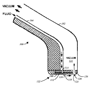
Figure 17 illustrates one alternative embodiment of the cleaning head 106 of
the invention wherein a single bar jet assembly 122 of the invention is
coupled to a
hand-held wand having a nozzle 192 having the half funnel shaped cleaning
fluid discharge
chamber 112 coupled to the cleaning fluid source via a feed tube 194 for
delivering liquid
cleaning fluid. The feed tube 194 is structured for being coupled to the
source of pressurized
liquid cleaning fluid via the cleaning fluid delivery tube 110 (shown in
Figure 2). The
cleaning fluid discharge chamber 112 again terminates in the angled striker
plate 114 that is
adjacent to the angled discharge slot or groove 116 opening onto one side of
the cleaning
head operating surface 118. Spaced away from the angled discharge orifice 116
across the
expanse of the operating surface 118 is the cleaning fluid and soil retrieval
slot or groove
120 formed in part by the cleaning fluid retrieval slot surface 123 and
coupled to the vacuum
18
CA 02555952 2006-08-11
WO 2005/082216 PCT/US2005/000610
chamber 121 that is constructed in the cleaning head 106. The vacuum chamber
121 is
structured to be coupled to the cleaning system vacuum source via the vacuum
hose 104. In
operation, the alternative hand-held embodiment of the invention is as
described herein.
Alternative Embodiments
Figures 18, 19 and 20 illustrate one alternative embodiment of the bar jet
assembly 122 of the invention, wherein Figure 18 is a top plan view looking at
the cleaning
fluid input face 140 of the alternative bar jet assembly 122, Figure 19 is a
bottom plan view
looking at the operational cleaning face of the alternative bar jet assembly
122, and Figure
19 is a cross-sectional view of the alternative bar jet assembly 122 taken
through the top plan
view of Figure 18. The cleaning fluid input face 140 of the bar jet assembly
122 is a planar
surface embodied as the flat aluminum or aluminum alloy base plate 142 which
is structured
for mounting and sealing to the cleaning surface of the rotary cleaning plate
124 by the
threaded fasteners 136 shown in Figure 5. The cleaning fluid discharge chamber
112 is open
and exposed for connection to the cleaning fluid distribution channel 134 of
the distribution
manifold 132 shown in Figure 4. As embodied in Figure 18, the cleaning fluid
discharge
chamber I 12 is a box-shaped space formed by a substantially rectangular
aperture in the base
plate 142 and substantially closed on its output surface by the striker plate
114 formed
substantially perpendicular to the cleaning fluid input face 140 such that the
cleaning fluid
discharge chamber 112 is shown in Figure 20 to have a substantially
rectangular
cross-section. The throat 158 of the discharge chamber 112 is eliminated with
the discharge
orifice I I6 opening onto the cleaning head operating surface 118 along one
edge adjacent to
the upright wall 144 (shown in Figures 19, 20), such that the discharge
orifice 116
communicates directly between the fluid discharge chamber 112 and the
operating surface
118. Accordingly, the discharge orifice 116 is a formed between the machined
surfaces I54,
156 (shown more clearly in Figures 21, 22) of the two cover plates 146, 148,
with the
discharge orifice I 16 being provided substantially crosswise or perpendicular
to the fluid
input face 140 of the bar jet assembly 122.
On either side of the cleaning fluid discharge chamber I 12 one or more of the
more locating pins 138 are provided for locating the pair of corrosion
resistant or stainless
steel cover plates 146, 148 (shown in Figures 19, 20) of the bar jet assembly
122 relative to
the cleaning fluid output surface 150 of the base plate 142 which has the
cleaning fluid
discharge chamber 112 formed therein. One or more of the fastener through
holes I 52 are
19
CA 02555952 2006-08-11
WO 2005/082216 PCT/US2005/000610
machined in the base plate 142 on either side of the cleaning fluid discharge
chamber 112 for
securing the bar jet assembly 122 to the cleaning surface of the rotary
cleaning plate 124 by
one or more of the threaded fasteners 136.
The two surfaces 154, 156 of the discharge orifice 116 are both upright or
even perpendicular relative to the cleaning surface of the rotary cleaning
plate 124 (shown in
phantom). While effectiveness of the cleaning head 106 in reducing cleaning
fluid
penetration is enhanced when the discharge orifice 116 is closer to parallel
with the cleaning
surface of the rotary cleaning plate 124, the cleaning head 106 is
alternatively oriented
perpendicular thereto. The two discharge slot surfaces 154, 156 are oriented
substantially
parallel to one another and spaced only a short distance apart so that the
discharge orifice
116 is very narrow, as discussed herein.
The cleaning fluid retrieval slot surface 123 is a substantially planar
surface
that is oriented to form a right angle with cleaning head operating surface
118.
Figure 19 is an bottom view of the bar jet assembly 122 showing the
operational surface thereof and illustrating each of the two cover plates 146,
148 secured to
the base plate 142 with one or more of the press-fit pins 138 and machined
with one or more
of the counter-sunk through holes 160 for securing the bar jet assembly 122 to
the cleaning
surface of the rotary cleaning plate 124 by one or more of the threaded
fasteners 136. Figure
19 also illustrates that, according to one embodiment of the invention, the
portion of the
discharge orifice 116 formed between the two cover plates 146, 148 extends the
entire length
of the bar jet assembly 122, while the discharge chamber 112 is truncated at
both ends
without extending to the ends of the bar jet assembly 122.
Figure 20 is the cross-sectional view taken through the top plan view of
Figure 18 and illustrates the fluid discharge chamber 112 being formed of the
crosswise
striker plate 114 and the upright wall 144 and terminating in the upright
discharge orifice
I 16. As illustrated in Figure 20, the leading discharge slot surface 156,
which is formed in
the leading cover plate 148, is aligned with the upright wall 144 portion of
the fluid
discharge chamber 112, and the trailing discharge slot surface 154, which is
formed in the
trailing cover plate 146, is spaced behind the leading discharge slot surface
156. Thus,
cleaning fluid entering the fluid discharge chamber 112 must impact with the
striker plate
114 before exiting the discharge chamber 112 through the discharge orifice 116
under
pressure.
CA 02555952 2006-08-11
WO 2005/082216 PCT/US2005/000610
Figures 21 and 22 are end views, respectively, of the forward or leading cover
plate 148 and the aft or following cover plate 146 according to the
alternative embodiment of
the invention illustrated in Figures 18, 19, 24. Accordingly, the leading
discharge slot
surface 156 of the leading cover plate 148 is illustrated in Figure 21 as
being oriented at a
substantially right angle b or perpendicular to the substantially planar
mounting surface 186
by which the forward cover plate 148 is mounted to the base plate 142 in the
bare jet
assembly 122. Stated differently, the leading discharge slot surface 156 is
oriented at an
angle of about 90 degrees from the mounting surface 186. The cleaning fluid
retrieval slot
surface 123 that forms one portion of the cleaning fluid and sail retrieval
slot or groove 120
(shown Figures 3, 17) is embodied as the substantially planar surface oriented
to form a right
angle with both the mounting surface 186 and the operating surface 118.
Figure 22 illustrates the following discharge slot surface 154 of the
following
cover plate 146 as being oriented at the substantially right angle b or
perpendicular to the
substantially planar mounting surface 188 by which the following cover plate
146 is
mounted to the base plate 142 in the bare jet assembly 122. Stated
differently, the following
discharge slot surface 154 is oriented at an angle of about 90 degrees from
the mounting
surface 188. The following cover plate 146 is also provided with the
substantially planar skid
surface 190 that is spaced away from and mutually parallel with the mounting
surface 188.
As discussed herein, the cleaning head 106 rests on the skid surface 190
during operation for
maintaining the head 106 parallel with the carpeting or other surface to be
cleaned and for
maintaining the vacuum at the cleaning fluid and soil retrieval slot 120.
Figures 23, 24, 25 and 26 illustrate another alternative embodiment of the bar
jet assembly 122 ofthe invention, wherein Figure 23 is a top plan view looking
at the
cleaning fluid input face 140 of the alternative bar jet assembly 122, Figure
24 is a bottom
plan view looking at the operational cleaning face of the alternative bar jet
assembly 122,
and Figures 25 and 26 are alternative cross-sectional views of the alternative
bar jet
assembly 122 taken through the top plan view of Figure 23. In the embodiment
of Figures
23, 24 and 25 the discharge orifice 116 is embodied as a substantially linear
pattern of
multiple discharge slots 196 formed, by example and without limitation, as a
line of
discharge slots 196 communicating between one the discharge chamber 112 and
the
operating surface 118. The multiple discharge slots 196 are cut about 8 to 10
thousands of an
inch or less deep such that each discharge slot 196 is on the order of about
0.008 inch to
21
CA 02555952 2006-08-11
WO 2005/082216 PCT/US2005/000610
0.010 inch or less in depth. However, discharge slots 196 alternatively cut
0.010 inch to
about 0.017 inch in depth or even as much as 0.020 inch in depth are also
effective for
forming the uniform sheet of liquid cleaning fluid according to the invention.
The depth of
the discharge slots 196 is limited to the degree that sufficient back pressure
is developed in
the discharge chamber 112 so that the cleaning fluid is discharge from the
accumulated slots
196 under pressure, rather than flowing freely from the discharge slots 196.
The length of the
discharge slots 196 as measured along the discharge slot surfaces 154, 156 can
be varied
from the minimum slot width of about 0.008 inch to as much as the entire
length of the
discharge chamber 112, without materially affecting the practice of the
invention. Spacing
between the individual discharge slots 196 can be varied from very close to
widely spaced,
without materially affecting the practice of the invention, as long as
sufficient liquid
cleaning fluid volume is discharged through the discharge slots 196 to form a
substantially
uniform sheet of liquid across a major portion of the operating surface 118 of
the leading
cover plate 148.
By example and without limitation, the discharge slots 196 are formed along
the leading edge of the discharge chamber 112 adjacent to the leading upright
wall 144.
However, the pattern of discharge holes 196 is alternatively formed adjacent a
trailing edge
198 of the discharge chamber 112, or alternatively, between the leading and
trailing edges
144, 198 without materially affecting the practice of the invention. The
pattern of discharge
slots 196 is formed, by example and without limitation, spaced apart as by
comb teeth along
the leading edge 154 of the trailing or following cover plate 146, or
alternatively, along the
trailing edge 156 of the leading cover plate 148.
In the embodiment of Figure 25 the pattern of discharge slots 196 that form
the discharge orifice 116 are formed crosswise or substantially perpendicular
to the operating
surface 118 as described in connection with the embodiment of Figures 18-22.
In the
alternative embodiment illustrated in Figure 26 the pattern of discharge slots
196 that form
the discharge orifice 116 are formed at angle to the operating surface 118 as
described in
connection with the embodiment of Figures 6-9.
In the embodiment of Figures 23, 24, 25 and 26 the cleaning fluid discharge
chamber 112 is substantially closed on its output surface by the striker plate
114 which is
either the angled striker plate illustrated in Figure 3, or the crosswise
striker plate illustrated
in Figure 20, without materially affecting the practice of the invention.
22
CA 02555952 2006-08-11
WO 2005/082216 PCT/US2005/000610
Figures 27, 28, 29 and 30 illustrate another alternative embodiment of the bar
jet assembly 122 of the invention, wherein Figure 27 is a top plan view
looking at the
cleaning fluid input face 140 of the alternative bar jet assembly 122, Figure
28 is a bottom
plan view looking at the operational cleaning face of the alternative bar jet
assembly 122,
and Figures 29 and 30 are alternative cross-sectional views of the alternative
bar jet
assembly 122 taken through the top plan view of Figure 27. In the embodiment
of Figures
2?, 28, 29 and 30 the discharge orifice 116 is embodied as a substantially
linear pattern of
discharge apertures or holes 200 formed, by example and without limitation, as
a line of
substantially round discharge holes 200 communicating as by drilling between
one the
discharge chamber 112 and the operating surface 118. By example and without
limitation,
the discharge holes 200 are formed along the leading edge of the discharge
chamber 112
adjacent to the leading upright wall 144. However, the pattern of discharge
holes 196 is
alternatively formed adjacent the trailing edge 198 of the discharge chamber
112, or
alternatively, between the leading and trailing edges 144, 198 without
materially affecting
the practice of the invention. The discharge holes 200 are sized to discharge
a sufficient
liquid cleaning fluid volume through the pattern of discharge holes 200 to
form a
substantially uniform sheet of liquid across a major portion of the operating
surface 118. The
multiple discharge holes 200 are about 8 to 10 thousands of an inch or less in
diameter.
However, discharge holes 200 alternatively made 0.010 inch to about 0.017 inch
in diameter
or even as much as 0.020 inch diameter are also effective for forming the
uniform sheet of
liquid cleaning fluid according to the invention. The diameter of the
discharge holes 200 is
limited to the degree that sufficient back pressure is developed in the
discharge chamber 112
so that the cleaning fluid is discharge from the accumulated holes 200 under
pressure, rather
than flowing freely from the discharge holes 200. The length of the pattern of
discharge
holes 200 is optionally as much as the entire length of the discharge chamber
112. Spacing
between adjacent holes 200 can be varied from very close to widely spaced,
without
materially affecting the practice of the invention, as long as sufficient
liquid cleaning fluid
volume is discharged through the discharge slots 196 to form a substantially
uniform sheet
of liquid across a major portion of the operating surface 118.
The pattern of discharge holes 200 forming the discharge orifice 116 is
formed in the leading edge 154 of the trailing or following cover plate 146,
or alternatively,
along the trailing edge 156 of the leading cover plate 148.
23
CA 02555952 2006-08-11
WO 2005/082216 PCT/US2005/000610
According to one embodiment of the invention, the pair of leading and
trailing cover plates 146, 148 is replaced with a single corrosion resistant
or stainless steel
cover plate 202, as illustrated in Figure 28, having formed therethrough the
pattern of
discharge holes 200 forming the discharge orifice 116 of the invention.
In the embodiment of Figure 29 the pattern of discharge holes 200 that form
the discharge orifice 116 are formed crosswise or substantially perpendicular
to the operating
surface 118 as described in connection with the embodiment of Figures 18-22.
In the
alternative embodiment illustrated in Figure 30 the pattern of discharge holes
200 that form
the discharge orifice 116 are formed at angle to the operating surface 118 as
described in
connection with the embodiment of Figures 6-9.
In the embodiment of Figures 27, 28, 29 and 30 the cleaning fluid discharge
chamber 112 is substantially closed on its output surface by the striker plate
114 which is
either the angled striker plate illustrated in Figure 3, or the crosswise
striker plate illustrated
in Figure 20, without materially affecting the practice of the invention.
While the preferred embodiment of the invention has been illustrated and
described, it will be appreciated that various changes can be made therein
without departing
from the spirit and scope of the invention.
24