Note: Descriptions are shown in the official language in which they were submitted.
CA 02556109 2006-08-11
ROLLING CONE DRILL BIT HAVING NON-CIRCUMFERENTIALLY
ARRANGED CUTTER ELEMENTS
BACKGROUND OF THE INVENTION
The invention relates generally to earth-boring bits used to drill a borehole
for the ultimate
recovery of oil, gas or minerals. More particularly, the invention relates to
rolling cone rock bits
and to an improved cutting structure for such bits. Still more particularly,
the invention relates to
enhancements in cutter element placement so as to decrease the likelihood of
bit tracking.
An earth-boring drill bit is typically mounted on the lower end of a drill
string and is
rotated by rotating the drill string at the surface or by actuation of
downhole motors or turbines, or
by both methods. With weight applied to the drill string, the rotating drill
bit engages the earthen
formation and proceeds to form a borehole along a predetermined path toward a
target zone. The
borehole thus created will have a diameter generally equal to the diameter or
"gage" of the drill bit.
An earth-boring bit in common use today includes one or more rotatable cutters
that
perform their cutting function due to the rolling movement of the cutters
acting against the
formation material. The cutters roll and slide upon the bottom of the borehole
as the bit is rotated,
the cutters thereby engaging and disintegrating the formation material in its
path. The rotatable
cutters may be described as generally conical in shape and are therefore
sometimes referred to as
rolling cones or rolling cone cutters. The borehole is formed as the action of
the rotary cones
remove chips of formation material which are carried upward and out of the
borehole by drilling
fluid which is pumped downwardly through the drill pipe and out of the bit.
The earth disintegrating action of the rolling cone cutters is enhanced by
providing the
cutters with a plurality of cutter elements. Cutter elements are generally of
two types: inserts
formed of a very hard material, such as tungsten carbide, that are press fit
into undersized apertures
I
CA 02556109 2006-08-11
in the cone surface; or teeth that are milled, cast or otherwise integrally
formed from the material
of the rolling cone. Bits having tungsten carbide inserts are typically
referred to as "TCI" bits or
"insert" bits, while those having teeth formed from the cone material are
known as "steel tooth
bits." In each instance, the cutter elements on the rotating cutters break up
the formation to form
the new borehole by a combination of gouging and scraping or chipping and
crushing.
hl oil and gas drilling, the cost of drilling a borehole is very high, and is
proportional to the
length of time it takes to drill to the desired depth and location. The time
required to drill the well,
in turn, is greatly affected by the number of times the drill bit must be
changed before reaching the
targeted formation. This is the case because each time the bit is changed, the
entire string of drill
pipe, which may be miles long, must be retrieved from the borehole, section by
section. Once the
drill string has been retrieved and the new bit installed, the bit must be
lowered to the bottom of the
borehole on the drill string, which again must be constructed section by
section. As is thus
obvious, this process, known as a "trip" of the drill string, requires
considerable time, effort and
expense. Accordingly, it is always desirable to employ drill bits which will
drill faster and longer,
and which are usable over a wider range of formation hardness.
The length of time that a drill bit may be employed before it must be changed
depends
upon its rate of penetration ("ROP"), as well as its durability. The form and
positioning of the
cutter elements upon the cone cutters greatly impact bit durability and ROP,
and thus are critical to
the success of a particular bit design.
To assist in maintaining the gage of a borehole, conventional rolling cone
bits typically
employ a heel row of hard metal inserts on the heel surface of the rolling
cone cutters. The heel
surface is a generally frustoconical surface and is configured and positioned
so as to generally align
with and ream the sidewall of the borehole as the bit rotates. The inserts in
the heel surface contact
2
CA 02556109 2006-08-11
the borehole wall with a sliding motion and thus generally may be described as
scraping or
reaming the borehole sidewall. The heel inserts function primarily to maintain
a constant gage and
secondarily to prevent the erosion and abrasion of the heel surface of the
rolling cone. Excessive
wear of the heel inserts leads to an undergage borehole, decreased ROP,
increased loading on the
other cutter elements on the bit, and may accelerate wear of the cutter
bearings, and ultimately lead
to bit failure.
Conventional bits also typically include one or more rows of gage cutter
elements. Gage
cutter elements are mounted adjacent to the heel surface but orientated and
sized in such a manner
so as to cut the corner of the borehole. In this orientation, the gage cutter
elements generally are
required to cut both the borehole bottom and sidewall. The lower surface of
the gage cutter
elements engage the borehole bottom, while the radially outermost surface
scrapes the sidewall of
the borehole.
Conventional bits also include a number of additional rows of cutter elements
that are
located on the cones in rows disposed radially inward from the gage row. These
cutter elements
are sized and configured for cutting the bottom of the borehole and are
typically described as inner
row cutter elements and, as used herein, may be described as bottomhole cutter
elements. Such
cutters are intended to penetrate and remove formation material by gouging and
fracturing
formation material. In many applications, inner row cutter elements are
relatively long and sharper
than those typically employed in the gage row or the heel row where the
inserts ream the sidewall
of the borehole via a scraping or shearing action.
A condition detrimental to efficient and economical drilling is known as
"tracking."
Tracking occurs when the inserts or cutting teeth of a cone cutter fall into
the same depressions or
indentations that were made by the bit during a previous revolution. Tracking
creates a pattern of
3
CA 02556109 2006-08-11
hills and valleys, known as "rock teeth" or "rock ribs," on the bottom of the
borehole. This pattern
may closely match the pattern of the cutter elements extending from the cone
cutters, making it
more difficult for the cutter elements to reach the uncut rock at the bottom
of the valleys. Thus,
tracking prevents the cutter elements from fully and efficiently penetrating
and disengaging the
formation material at the bottom of the borehole. Because the cutter elements
penetrate into an
indentation previously formed, rather than making a fresh indentation that is
offset from prior
indentations, the disintegration action of the cutting elements is less
efficient. In part, this is
because the weight-on-bit is distributed to the flanks of the cutter elements,
rather than to the
relatively sharp crests of the cutter elements. Thus, tracking slows the
drilling process and makes
it more costly.
Further, the sculptured pattern on the borehole bottom may tend to
redistribute the weight-
on-bit from the cutter elements to the surface of the cone cutters. This not
only impedes deep
penetration of the cutter elements, but may lead to damage to the cone and the
cone bearings. Such
damage may occur because the cone itself becomes more directly exposed to
significant impact or
transient loads which may tend to cause premature seal and/or bearing failure.
Thus, tracking is
known to seriously impair the penetration rate, life and performance of an
earth boring bit.
Increasing ROP while maintaining good cutter and bit life to increase the
footage drilled is
an important goal in order to decrease drilling time and recover valuable oil
and gas more
economically. Decreasing the likelihood of bit tracking would further that
desirable goal.
Accordingly, there remains a need in the art for a drill bit and cutting
structure that tends to
prevent tracking so as to yield an increase in ROP and footage drilled, and
eliminate other
detrimental effects.
4
CA 02556109 2006-08-11
SUMMARY OF THE PREFERRED EMBODIMENTS
Accordingly, there is described herein a rolling cone drill bit including
multiple cones with
regions of intermeshing and non-intermeshing cutter elements. In the non-
intermeshed regions, an
array of cutter elements is disposed in a band extending about the cone
surface. The array is a non-
circumferential arrangement, with the cutter elements being mounted at
nonuniform radial
distances relative to the bit axis. This non-circumferential arrangement,
which may be a spiral,
multiple spirals, other patterns of staggered or offset cutter elements, or a
random arrangement,
provides a composite cutting profile having substantial cutting width, and one
that is free of ridge-
producing voids. In certain embodiments, the composite cutting profiles of the
arrays at least
partially overlap, and may be arranged to cover the entire non-intermeshed
region on the cones or
only some portion of that region. Arrays in which the cutter elements have non-
uniform radial
positions and thus are non-circumferentially arranged provide enhanced
bottomhole coverage, and
offer the potential to reduce the likelihood of bit tracking. These and
various other features and
characteristics of above-mentioned arrays, cone cutters and drill bits are
described in more detail
below, and will be readily understood and appreciated upon reading the
following detailed
description of the preferred embodiments, and by referring to the accompanying
drawings
BRIEF DESCRIPTION OF THE DRAWINGS
For a more detailed description of the preferred embodiment of the present
invention,
reference will now be made to the accompanying drawings, wherein:
Figure 1 is a perspective view of an earth-boring bit made in accordance with
the principles
of the present invention.
Figure 2 is a partial section view taken through one leg and one rolling cone
cutter of the
bit shown in Figure 1.
5
CA 02556109 2006-08-11
Figures 3A and 3B are, respectively, front and rear elevation or profile views
of one of the
cone cutters of the bit shown in Figures 1 and 2.
Figure 4 is a partial schematic view showing, in rotated profile, the cutting
paths of certain
of the cutter elements disposed in the cone cutter shown in Figures 3A and 3B.
Figures 5A and 5B are, respectively, front and rear elevation or profile views
of another of
the cone cutters of the bit shown in Figures 1 and 2.
Figures 6A and 6B are, respectively, front and rear elevation or profile views
of another of
the cone cutters of the bit shown in Figures 1 and 2.
Figure 7 is a partial section view showing, schematically and in rotated
profile, the paths of
all of the cutter elements of the three cone cutters of the drill hit shown in
Figure 1.
Figure 8 is a schematic representation showing a cross-sectional view of the
three rolling
cones of the bit shown in Figure 1.
Figure 9 is an elevation view of another cone cutter having application in a
rolling cone bit
such as the bit of Figures 1 and 2.
Figure 10 is a partial elevation view of another cone cutter having
application in a rolling
cone bit, such as the bit of Figures 1 and 2.
Figure 11 is a partial section view showing, schematically and in rotated
profile, the cutting
profiles of certain cutter elements of the cone cutter shown in Figure 10.
Figure 12 is an elevation view of another cone cutter that may be employed in
the rolling
cone bit of Figures 1 and 2 as viewed looking toward the backface of the cone
cutter.
Figure 13 is a partial section view showing, schematically and in rotated
profile, the cutting
profiles of certain cutter elements of the cone cutter shown in Figure 12.
Figure 14A is an elevation view of another cone cutter that may be employed in
the rolling
6
CA 02556109 2006-08-11
cone bit of Figures 1 and 2 as viewed looking toward the backface of the cone
cutter.
Figure 14B is a side elevation view, in schematic form, showing the
arrangement of cutter
elements on the rolling cone cutter of Figure 14A.
DETAILED DESCRIPTION OF THE PREFERRED EMBODIMENTS
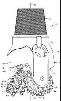
Referring first to Figure 1, an earth-boring bit 10 is shown to include a
central axis 11 and a
bit body 12 having a threaded section 13 at its upper end that is adapted for
securing the bit to a
drill string (not shown). Bit 10 has a predetermined gage diameter as defined
by the outermost
reaches of three rolling cone cutters 1, 2, 3 (cones I and 2 shown in Figure
1) which are rotatably
mounted on bearing shafts that depend from the bit body 12. Bit body 12 is
composed of three
sections or legs 19 (two shown in Figure 1) that are welded together to form
bit body 12. Bit 10
further includes a plurality of nozzles 18 that are provided for directing
drilling fluid toward the
bottom of the borehole and around cone cutters 1-3. Bit 10 includes lubricant
reservoirs 17 that
supply lubricant to the bearings that support each of the cone cutters. Bit
legs 19 include a shirttail
portion 16 that serves to protect the cone bearings and cone seals from damage
caused by cuttings
and debris entering between leg 19 and its respective cone cutter.
Referring now to both Figures 1 and 2, each cone cutter 1-3 is mounted on a
pin or journal
extending from bit body 12, and is adapted to rotate about a cone axis of
rotation 22 oriented
generally downwardly and inwardly toward the center of the bit. Each cutter 1-
3 is secured on pin
20 20 by locking balls 26, in a conventional manner. In the embodiment shown,
radial and axial
thrust are absorbed by journal sleeve 28 and thrust washer 31. The bearing
structure shown is
generally referred to as a journal bearing or friction bearing; however, the
invention is not limited
to use in bits having such structure, but may equally be applied in a roller
bearing bit where cone
7
CA 02556109 2006-08-11
cutters 1-3 would be mounted on pin 20 with roller bearings disposed between
the cone cutter and
the journal pin 20. In both roller bearing and friction bearing bits,
lubricant may be supplied from
reservoir 17 to the bearings by apparatus and passageways that are omitted
from the figures for
clarity. The lubricant is sealed in the bearing structure, and drilling fluid
excluded therefrom, by
means of an annular seal 34 which may take many forms. Drilling fluid is
pumped from the
surface through fluid passage 24 where it is circulated through an internal
passageway (not shown)
to nozzles 18 (Figure 1). The borehole created by bit 10 includes sidewall 5,
corner portion 6 and
bottom 7, best shown in Figure 2.
Referring still to Figures 1 and 2, each cutter 1-3 includes a generally
planar backface 40
and nose portion 42. Adjacent to backface 40, cutters 1-3 further include a
generally frustoconical
surface 44 that is adapted to retain cutter elements that scrape or ream the
sidewalls of the borehole
as the cone cutters rotate about the borehole bottom. Fnistoconical surface 44
will be referred to
herein as the "heel" surface of cone cutters 1-3, it being understood,
however, that the same surface
may be sometimes referred to by others in the art as the "gage" surface of a
rolling cone cutter.
Extending between heel surface 44 and nose 42 is a generally conical surface
46 adapted
for supporting cutter elements that gouge or crush the borehole bottom 7 as
the cone cutters rotate
about the borehole. Frustoconical heel surface 44 and conical surface 46
converge in a
circtimferential edge or shoulder 50. Although referred to herein as an "edge"
or "shoulder," it
should be understood that shoulder 50 may be contoured, such as by a radius,
to various degrees
such that shoulder 50 will define a contoured zone of convergence between
frustoconical heel
surface 44 and the conical surface 46. Conical surface 46 is divided into a
plurality of generally
frustoconical regions or bands 48 generally referred to as "lands" which are
employed to support
and secure the cutter elements as described in more detail below. Cone 2
includes three such lands
8
CA 02556109 2006-08-11
48a-c. Grooves 49 are formed in cone surface 46 between adjacent lands 48a-c.
In the bit shown in Figures 1 and 2, each cone cutter 1-3 includes a plurality
of wear
resistant inserts 60, 61, 62, 63. These inserts each include a generally
cylindrical base portion with
a central axis, and a cutting portion that extends from the base portion and
includes a cutting
surface for cutting formation material. The cutting surface may be symmetric
or asymmetric
relative to the insert axis. All or a portion of the base portion is secured
by interference fit into a
mating socket drilled into the surface of the cone cutter. The "cutting
surface" of an insert is
defined herein as being that surface of the insert that extends beyond the
surface of the cone cutter.
The extension height of the cutter element is the distance from the cone
surface to the outermost
point of the cutting surface (relative to the cone axis) as measured parallel
to the insert's axis.
Referring now to Figures 3A and 3B, cone cutter 2 is shown in more detail and
generally
includes a substantially planar backface 40 and a nose 42 opposite backface
40. Cone cutter 2
further includes a generally frustoconical heel surface 44 adjacent to
backface 40 and a generally
conical surface 46 extending between heel surface 44 and nose 42. Cone 2
further includes a
circumferential row of heel cutter elements 60 extending from heel surface 44.
In this
embodiment, heel row cutter element 60 are generally flat-topped elements
designed to ream the
borehole sidewall.
Adjacent to shoulder 50 and radially inward of the heel row cutters, cone 2
includes a
circumferential row of gage cutter elements 61. In this embodiment, elements
61 include a cutting
surface having a generally slanted crest and are intended for cutting the
corner of the borehole 6
(Figure 2), although any of a variety of cutter elements may be employed in
this location. Cone
cutting inserts 61 are referred to herein as gage or gage row cutter elements.
However, others in
the art will describe such cutter elements as heel cutters or heel row
cutters.
9
CA 02556109 2006-08-11
Between the circumferential row of gage cutter elements 61 and nose 42, cone
cutter 2
includes a number of rows and other arrangements of bottomhole cutter elements
62. Bottomhole
cutter elements 62 are intended primarily for cutting the bottom of the
borehole and, for example,
may include cutting surfaces having a generally rounded chisel shape as shown
in Figures 3A, 3B,
although other shapes may be employed.
Cone 2 fiirther includes a plurality of ridge cutter elements 63 (one each
shown in the views
of Figures 3A and 3B). Ridge cutter elements 63 are intended to cut portions
of the hole bottom 7
that are otherwise left uncut by cutting paths of the other bottomhole cutter
elements 62.
Referring again to Figure 3A, the cutter elements disposed on cutter 2 may
generally be
described as being disposed or positioned in six different groupings or
arrangements. For example,
cone cutter 2 includes a nose row 2A which includes three substantially
identical bottomhole cutter
elements 62 that are mounted in the cone cutter at nominally the same radial
position so that these
cutter elements 62 cut in a single swath or track in the formation. Likewise,
cone cutter 2 includes
a row 2B of bottomhole cutter elements 62. All cutter elements of row 2B are
of substantially
similar size and shape, and each is located in the same nominal radial
position so as to form a
circumferential row 2B that is spaced apart from row 2A. Disposed between row
2A and row 2B
is a row 2A' including a plurality of ridge cutter elements 63.
Continuing to move toward the backface 40, cone cutter 2 includes an array 2C
of
bottomhole cutter elements 62. As described in more detail below, the cutter
elements of array 2C
are not disposed in a circumferential row as are the elements of rows 2A and 2
B where, within
manufacturing tolerances, the row's elements are mounted in the same radial
position and therefore
may be referred to herein as being redundant cutter elements or as being
located in redundant
positions. The cutter elements of array 2C are instead disposed in non-uniform
radial positions
CA 02556109 2006-08-11
(relative to the bit axis 11) such that the cutter elements in array 2C do not
cut in an identical paths
but instead cut in offset or staggered paths. Having this arrangement, the
cutter elements of 2C are
described as being non-circumferentially arranged, and are therefore arranged
differently than in
the conventional arrangement where they are placed in circumferential rows.
Adjacent to array 2C
are the gage row cutter elements 61 which, in this embodiment, are arranged in
a circumferential
row 2D. The heel surface 44 retains a circumferential row 2E of heel row
cutter 60.
An annular groove 49a separates row 2A from row 2B. Likewise, a groove 49b is
disposed
between row 2B and array 2C. Grooves 49a, b permit cleaning of the cone cutter
by allowing fluid
flow between the adjacent rows of cutters, and further permits the cutter
elements from adjacent
cone cutters 1, 3 to intermesh with the cutter elements of cone 2.
More specifically, performance expectations of rolling cone bits require that
the cone
cutters be as large as possible within the borehole diameter so as to allow
use of the maximum
possible bearing size and to provide a retention depth adequate to secure the
cutter element base
within the cone steel. To achieve maximum cone cutter diameter and still have
acceptable insert
retention and protrusion, some of the rows of cutter elements are arranged to
pass between the
rows of cutter elements on adjacent cones as the bit rotates. In some cases,
certain rows of cutter
elements extend so far that clearance areas or grooves corresponding to
cutting paths taken by
cutter elements in these rows are provided on adjacent cones so as to allow
the bottomhole cutter
elements on adjacent cutters to intermesh farther. The term "intermesh" as
used herein is defined to
mean overlap of any part of at least one cutter element on one cone cutter
with the envelope
defined by the maximum extension of the cutter elements on an adjacent cutter.
Thus, grooves 49a
and 49b allow the cutting surfaces of certain bottomhole cutter elements 62 of
cone cutters 1 and 3
to pass between the cutter elements of rows 2A and 2B, and between row 2B and
array 2C without
11
CA 02556109 2006-08-11
contacting cone surface 46 of cone cutter 2.
In this way, cone cutter 2 may therefore be described as being divided into an
intermeshed
region 70 and a non-intermeshed region 72. In particular, rows 2A and 2B of
cone cutter 2 lie in the
intermeshed region 70, while the cutter elements of arrangements 2C, 2D and 2E
are in the non-
intermeshed region of cone cutter 2.
In the embodiment shown in Figures 3A and 3B, the cutter elements of array 2C
are not
retained in the cone cutter at the same radial position, but instead are
located in differing radial
positions. In this particular embodiment, each cutter element 62 of array 2C
is disposed in a
different radial position. For purposes of further explanation, each of the
inner row cutter elements
62 of array 2C are assigned reference numerals 2C-1 through 2C-14, there being
fourteen cutter
elements 62 in array 2C in this embodiment. Cutter elements 2C-1 through 2C-14
are disposed on a
generally frustoconical-shaped region or band 48c which encircles the cone and
which is located in
the non-intermeshed region 72 between the circumferential row 2D of gage row
cutter elements
and the circumferential row 2B of the intermeshed region 70.
As cone cutter 2 rotates in the borehole in the direction represented by arrow
80, cutter
elements 2C-1 through 2C-14 periodically hit the borehole bottom, with each
hit intended to
dislodge a volume of the formation material in order to advance the borehole.
When the cutting
surfaces of cutter elements 2C-1 through 2C-14 are viewed as they would appear
if rotated into a
single plane, hereafter referred to as "viewed in rotated profile," the cutter
surfaces of the elements
are positioned as shown in Figure 4. In this enlarged view, it can be seen
that the cutter element
2C-14 includes a cutting surface that cuts the closest to the borehole wall
while cutter element 2C-
1, the radially-innermost cutter element of the array, has a cutting surface
that cuts closest to the bit
axis 11 and furthest from the borehole wall. The profiles of elements 2C-2
through 2C-10 have
12
CA 02556109 2006-08-11
been omitted for clarity. It will nevertheless be understood that cutter
elements 2C-2 through 2C-
13 cut at locations radially between cutter elements 2C-1 and 2C-14. This
array 2C of cutter
elements, where a series of adjacent elements are positioned progressively
further (or closer) to the
bit axis, is generally described herein as a spiral arrangement or spiral
array.
In this specific arrangement, the radial positions of the cutter elements 2C-1
through 2C-14
are staggered equally. In other words, the cutter element axis 90 of each of
the cutter elements 2C-
1 through 2C-14 is spaced a uniform radial distance D from the element axis of
the immediately
adjacent cutter elements. In this example, where elements 2C-1 through 2C-14
have a diameter of
0.5625 inch, D is equal to approximately 0.015 inches. Other radial positions
and offsets may be
employed. Preferably, for bits having diameters of between 7 7/8 inch and 8
3/4 inch, D will be
between approximately 0.010 inches and 0.100 inches.
Likewise, in this embodiment, each of the fourteen cutter elements 2C-1
through 2C-14 are
angularly spaced about the cone axis 22 25.7 ; however, as desired or required
for clearance with
other inserts, the angular positioning of the cutter elements 2C-1 through 2C-
14 need not be
uniform. In the rotated profile shown in Figure 4, the inserts are positioned
in the cone at a
uniform angle of 0.5 relative to the bit axis 11 and generally perpendicular
to the cone surface.
However, in other embodiments, that angle may be more or less, and the angle
need not be uniform
among all cutter elements of an array. The composite cutting profile
represented by the
overlapping cutting profiles of cutter elements 2C-1 through 2C-14 has a width
W as measured
generally normal to the surface of frustoconical region 48a in this rotated
profile.
As cone 2 rotates in the borehole, cutter elements 2C-1 through 2C-14 will cut
substantially
the entire width W of the adjacent formation. In particular, the array will
cut a swath, leaving no
uncut borehole bottom, at least between the cutter element axes of the
radially-innermost and
13
CA 02556109 2008-07-09
outermost cutter elements. In other words, the cutter elements are positioned
closely enough such that, in
rotated profile, uncut ridges of formation are not formed between the adjacent
cutting positions within the
composite profile. By contrast, and referring momentarily in to Figure 7, it
can be seen that ridges R of
formation material may form between the adjacent and concentric
circumferential rows of cutter elements in
the intermeshed region 70. The overlapping and relatively close positioning,
in rotated profile, of the cutter
elements in array 2C shown in Figure 4 prevents ridges from forming. For this
reason, the array 2C and its
rotated profile W may be fairly described as being free of cutting voids or
ridge-producing voids.
Additionally, as perhaps best understood with reference to Figures 3B and 4,
given the substantial
radial distance that exists between the various cutter elements in array 2C as
a particular cutter element comes
into engagement with the formation, the likelihood that the cutting tip of
that element will fall within a
previously-formed crater or indentation is lessened such that the cone cutter
will tend not to track.
Referring now to Figures 5A and 5B, cone 3 includes backface 40, nose 42,
generally frustoconical
heel surface 44, and generally conical surface 46. Likewise, cone 3 includes
heel inserts 60, gage inserts 61,
bottomhole inserts 62 and ridge cutter elements 63, all as previously
described. Bottomhole cutter elements
62 are arranged in a first row 3A (consisting of a single insert), a spaced-
apart circumferential row 3B, and
another spaced-apart circumferential row 3C. In this embodiment, within each
row 3B and 3C, all of the
elements have substantially the same radial position and have overlapping and
aligned cutting profiles and
element axes. Disposed between rows 3B and 3C is a circumferential row 3B' of
ridge cutting elements 63.
Like cone 2, cone 3 includes a circumferential row 3G of heel inserts 60
spaced apart from a circumferential
row 3F of gage inserts 61.
14
CA 02556109 2006-08-11
Disposed between gage row 3F and inner row 3C is frustoconical region or land
81 upon
which are arranged an array 3D of twelve bottomhole cutter elements 62,
referenced herein as
elements 3D-1 through 3D-12. Rows 3A through 3C intermesh with rows of
bottomhole cutter
elements in cones I and 2 such that the region 70 may be described as the
intermeshed region on
cone 3, and the region 72 being the non-intermeshed region. As best shown in
Figure 5B, cutter
element 3D-1 is positioned closest to bit axis 11 while cutter element 3D-12
is furthest from bit
axis 11. Between those cutter elements, elements 3D-2 through 3D-11 are
mounted with each
being at a different radial position and with each being progressively further
from bit axis 11
forming a spiral array of elements. Relative to the direction of cone rotation
80, this array 3D of
cutter elements 3D-1 through 3D-12 spirals in the opposite direction from the
spiral arrangement of
cutter elements in array 2C on cone 2, previously described.
Referring now to Figures 6A and 6B, cone I includes backface 40, nose 42,
generally
frustoconical heel surface 44, and generally conical surface 46. Likewise,
cone 1 includes heel
inserts 60, gage inserts 61, bottomhole inserts 62, and ridge cutter elements
63, all as previously
described. Bottomhole cutter elements 62 are arranged in a first row 1
A(consisting of a single
insert) and a spaced-apart circumferential row 1B. All of the cutter elements
in row 1B nominally
have the same radial position and have overlapping and aligned cutting
profiles and element axes.
A circumferential row 1B' of ridge cutting elements 63 is disposed adjacent
row 1B. Cone I also
includes a circumferential row lE of heel inserts 60, spaced apart from a
circumferential row 1D of
gage inserts 61.
Between gage row ID and inner row 1 B' is frustoconical region 48d upon which
are
arranged an array 1C of fifteen bottomhole cutter elements 62, referenced here
as elements 1C-1
through 1 C-15. Rows I A and I B intermesh with rows of bottomhole cutter
elements 62 in cones 2
CA 02556109 2006-08-11
and 3 such that the region 70 may be described as the intermeshed region on
cone 1, and the region
72 being the non-intermeshed region.
Array 1 C includes fifteen inner row cutter elements 62 arranged in two
separate spiral
arrangements. Referring to Figure 6A, cutter elements 1C-1 and 1C-15 are
disposed closest to the
bit axis 11 and are disposed at the same radial position in this example and
thus are redundant
cutter elements. In relation to these two cutter elements, cutter elements IC-
2 through 1C-8 are
positioned in a spiral, each being progressively further from bit axis 11.
Cutter elements 1C-14
through 1 C-8 likewise are positioned progressively ftirther from bit axis 11
and are positioned in a
spiral arrangement, but one that spirals in the opposite direction. Thus, the
cutter elements of the
array I C are arranged in two spirals (of eight elements each) that spiral in
opposite directions. In
this fifteen cutter element array, cutter element 1C-8, the cutter element
furthest from bit axis 11, is
part of each spiral.
Referring again to Figure 7, there is shown, in rotated profile, the cutting
profiles of each of
the cutter elements of cones 1-3. The single nose row cutter of cone 3
represents a cutting profile
3A. Likewise, the single nose row cutter from cone I is represented by profile
lA which is spaced
radially inward from profile 3A. Cutting profiles of each of the cutter
elements in rows 2A, 3B,
1 B, 2B and 3C are represented by a single cutting profile having the same
designation. Likewise,
the circumferential rows of ridge cutter elements are each represented by a
single cutting profile
2B', 3B', and 1 B' given that each of the cutter elements in the respective
rows are generally aligned.
The cutter elements of the array 1 C of cone 1(having the two, oppositely
directed, spiral
arrangements) is represented by profile 1 C. The profiles of arrays 2C and 3D
are likewise shown.
The cutting profiles of the fifteen cutter elements of array 1 C form eight
spaced-apart cutting
profiles as two of the cutter elements in each of the separate spiral
arrangements are positioned in
16
CA 02556109 2008-07-09
the same position, and one cutter element is common to both spirals.
Particularly, the cutting profile
designated as 1C-1 is identical to the profile for redundant cutter element 1C-
15. The cutter element
designated 1 C-8 is the sole cutter element having a cutting profile in that
position.
With respect to cutting profile of elements of array 2C, each of the fourteen
cutter elements are
spaced at a different radial position, such that fourteen separate cutting
profiles combine to create the
composite cutting profile 2C. Cutter element 2C-1 is the radially-innermost
cutter element of the array
2C. Likewise, the twelve, radially-spaced cutter elements in array 3D
collectively define the composite
profile 3D. In this embodiment, it is evident that a substantial number of
cutter elements (twenty-six in
this example) are available for bottomhole cutting in the region immediately
adjacent to gage cutter
element 61, given the overlap of the cutter elements in each array 3D and 3C,
as well as the overlap
between the two composite cutting profiles 3D and 2C. In this arrangement, not
only is there substantial
overlap between the cutting profiles of 3D and 2C, but there is also overlap
between the cutting profiles of
3D with 1 C and of 2C with 1 C regions. Thus, this example demonstrates
overlap, in rotated profile, of the
composite cutting profile of cutter arrays of three cone cutters. The total
composite cutting profile of
these three arrays totally covers the borehole bottom from the cutting surface
of insert 1C-1 to the cutting
surface of the radially-outermost cutter element of array 3D, as measured
between the element axes of
those cutter elements. As shown, due to the spacing of the cutter elements
within each array, and due to
the overlap of the composite cutting profiles of the arrays, no uncut bottom
exists and no uncut ridges will
be formed between the elements of arrays 1 C and 3D. The total composite
cutting profile may therefore
be described as free of cutting voids or free of ridge-producing voids. In
this example, the total composite
cutting profile spans or encompasses the entire region between the intermeshed
cutter elements and the
gage row cutter elements. As will be described below, in other
17
CA 02556109 2006-08-11
embodiments, the total composite cutting profile that is free of cutting voids
may extend to include
the gage region and heel region, such that all regions of the cone cutters,
excluding the intermeshed
regions, will be free of cutting voids.
As can further be understood with reference to Figure 7, a bit may be designed
with more
or less space available for the gage row cutter elements depending, in part,
on the spacing of the
radially-outermost array of bottomhole cutter elements (array 3D in this
example). As will be
understood, if array 3D is positioned to overlap more with the array of 2C, or
if array 3D is
configured with some elements in redundant radial positions (such as arranged
into the eight
positions in the example of array 1C), then greater room will be afforded the
gage cutter elements.
1 fl In that instance, the gage row cutter elements may have a greater
diameter. Likewise, the gage
insert, given the latitude afforded by its position relative to the closest
bottomhole array, may have
a different extension height, a different or more desirable cutting shape, or
be made with a different
material or material enhancement. Similarly, varying the width and degree of
overlap between the
composite cutting profile of the nearest array of bottomhole cutter elements
provides the bit
designer with more latitude in the positioning of the gage cutter elements
relative to the hole wall
(engaging either higher or lower on the hole wall) and in the number of gage
inserts that may be
employed in the gage row. In a corresponding manner, the size, number,
diameter, extension,
shape and materials of the heel row cutter elements may likewise be varied on
a single cone, and
from cone to cone, depending upon the size, arrangement, and composite cutting
profile of the
gage row cutter elements.
Referring momentarily to Figure 8, the intermeshed relationship between the
cones 1-3 is
shown. In this view, commonly termed a "cluster view," the schematic
representation of cone 3 is
duplicated so that the intermesh between cones 2 and 3 and between cones 1 and
3 may be
18
CA 02556109 2006-08-11
depicted. As shown in Figure 8, in the intermeshed regions 70, the cutter
elements of cones 1-3 are
arranged in circumferential rows of elements where the elements of each row
are disposed at
substantially the same radial position. Outside or radially distant from the
intermeshed region 70 is
the non-intermeshed region 72 in which substantial bottomhole coverage is
provided by the spiral
arrays 1C, 2C and 3D, previously described. The composite cutting profile of
the arrays 1C, 2C
and 3D as shown to have cutting widths Wl, W2 and W3, respectively. In this
embodiment, W2 of
array 2C is larger than W, of array 1 C, and W I is larger than W3 of array
3D.
Although the arrays of cutter elements 1C, 2C and 3D have been depicted and
described as
spirals, other arrangements may be employed and still achieve expanded
bottomhole coverage and,
simultaneously, be positioned so as to potentially lessen the likelihood of
tracking. More
particularly, and referring, for example, to Figure 4, the same number of
cutter elements may be
employed in frustoconical region 48c and be positioned so that their cutting
surfaces, in rotated
profile, cover the entire width W without the elements being positioned in a
spiral. For example,
cutter elements 2C-1 through 2C-14 may be disposed each at a different radial
position so that, in
rotated profile, the entire width W of frustoconical region 48c is covered.
However, instead of
cutter elements 2C-1 thorough 2C-14 following each other in the numerically
consecutive manner
shown, those cutter elements may be randomly positioned about surface 48c so
that the cutter
elements do not progress in a spiral from the radially innermost cutter
element to the radially
outermost cutter element, but that still creates the same composite cutting
profile shown in Figure
4.
Similarly, and referring to Figures 6A and 6B of cone 1, the same complete
coverage of
frustoconical surface 48d could be maintained with the cutter elements of the
array 1C differently
positioned. As a specific example, instead of arranging the cutter elements in
two separate spirals,
19
CA 02556109 2008-07-09
pairs of cutter elements having the same radial position could be positioned
adjacent to one
another so that, upon moving about the cone axis 22 along frustoconical
surface 48d, there would
first be two cutter elements having the same innermost radial position,
followed by two cutter
elements having the next innermost radial position, and so on, until the final
cutter element in the
outermost radial position (cutter element 1C-8 shown in Figure 6B) would be
positioned.
Numerous other arrangements are possible. Arrays in which the cutter elements
have non-
uniform radial positions and thus are non-circumferentially arranged provides
both enhanced
bottomhole coverage and, significantly, offers the potential to lessen the
likelihood of tracking
occurring. In the non-uniform position of cutter elements of a given array, it
is unlikely that, as
the bit rotates in the borehole and the elements of the array rotate back to
the formation-engaging
position, they will impact the borehole bottom in a crater previously made by
a cutter element of
that array. This is the case both because the cutter elements of the given
array are at different
radial positions and because the non-intermeshed cutter elements of the
various cones are not in
the same radial position because their composite cutting profiles overlap.
This non-circumferential arrangement of cutter elements may also lead to
additional
enhancements in bit design. For example, referring now to Figure 9, there is
schematically shown
a cone cutter 100 including bottomhole cutter elements disposed in nose
circumferential row
100A, a second circumferential row of bottomhole cutter elements 100B, a
spiral array 100C of
bottomhole cutter elements, a circumferential row 100D of gage cutter
elements, and a
circumferential heel row 100E. As shown, array 100C includes a spiral
arrangement of fourteen
cutter elements, cutter elements 100C-1 to 100C-7 shown in Figure 9, in which
each cutter
element is positioned at a radially different location than the other elements
in the array. Cutter
element 100C-7 is closest to gage, while cutter 100C-1 is furthest from gage
and closest to bit
axis 11. Although the radial distance between adjacent elements of the array
is exaggerated in
this Figure, it will be understood that in a location such as the position of
100C-1, there is
CA 02556109 2008-07-09
substantially greater volume of cone steel and room for larger gage inserts,
as compared to the
region where element 100C-7 is positioned. This enables the cone cutter 100 to
employ gage row
cutters of non-uniform diameter. Specifically, gage insert 100D-1 may be
significantly larger in
diameter than gage insert 1 OOD-7. In particular, in addition to this design's
antitracking potential,
by providing gage inserts of larger diameter, the cone cutter 100 may be more
robust and durable
in its corner cutting capabilities, as compared to a cone cutter in which all
of the gage row cutter
elements are of a single and smaller diameter.
Additionally, and still referring to Figure 9, by placing the cutter elements
in array 100C
in differing radial positions, the cutter elements will endure differing
forces as they engage
formation material. For example, the radially innermost cutter element 100C-1,
being closer to
the bit axis, will experience more impact loading and can be made more durable
relative to insert
100C-7. In this particular example, insert 100C-7 is very close to gage row
and, as such, will
experience and engage in shearing cutting duty. In this application, it is
desirable that the cutter
element 100C-7 be made harder and more wear-resistant, as compared to cutter
element 100C-1.
As such, in this example, insert 100C-7 may be made of a harder, more wear-
resistant grade of
carbide, or other material, while insert 100C-1 may be made of a tougher, more
durable material.
Further properties of the cutter elements of a given non-circumferential array
may be
varied depending upon the application. Once again, referring to Figure 9, for
cutting in the
position show for cutter element 100C-1, it may be desirable that the cutter
element have a greater
diameter or greater extension, or both, compared to the cutter element shown
as 100C-7. For
cutter element 100C-1 that is furthest from gage and intended to have a
substantial share of the
bottomhole cutting duty, it may be desirable that cutter element 100C-1 be
provided with a
greater extension height than the cutter element in position 100C-7. Likewise,
the shape of the
cutter elements in an array may differ. Once again, it may be desirable that
the cutter element
100C-1 be an aggressive chisel shape, for example, while the cutter element
closer to gage, 100C-
21
CA 02556109 2008-07-09
7, may have a hemispherical cutting surface or a generally flat cutting
surface. In summary, the
cutter elements in a non- circumferentially arranged array may differ
substantially with regards to
insert diameter, extension height, shape of the cutting surface, and material
grades and material
coatings.
In the foregoing examples, cutter elements are disposed in the non-intermeshed
region of
the cone cutter in an array intended to prevent the cutter elements from
falling within previously-
made indentations so as to lessen the likelihood of bit tracking. The
composite cutting profiles
provided by these arrays further enhances bottomhole coverage by eliminating
large, uncut
regions. To best resist tracking, it is desired to space the cutter elements
of an array of non-
circumferentially arranged elements in at least five or more different radial
positions. The larger
the cone diameter in the region in which the array of elements is to be
placed, the greater the
number of different radial positions that can be employed. As explained above
with respect to
cone cutters 2 and 3, for a 7 7/8" diameter bit 10, it is useful to employ 7
or more radial positions
for cutter arrays that are immediately adjacent and radially inboard from the
gage row.
In the embodiments described above, the cutter element arrays in the non-
intermeshed
region extend generally from the outermost row of intermeshed cutter elements
to a gage row of
cutter elements that is generally adjacent the heel surface. However, these
arrays of offset and
non-circumferentially arranged cutter elements may continue outwardly so as to
encompass the
gage region and even the heel region. Referring now to Figure 10, cone cutter
200 is shown
including a generally frustoconical heel surface 44 and a generally conical
surface 46, as
previously described. The heel surface 44 retains a circumferential row 200D
of heel row cutter
elements. Adjacent to heel surface 44 is an array 200C of gage cutter elements
200C-1
22
CA 02556109 2006-08-11
through 200C-N (only elements C1-C7 being visible in this view). As shown,
element 200C-1 is
closest to the heel surface 44 with cutters 200C-2 ...C-N, each positioned
progressively further
from heel surface 44 (and closer to bit axis 11). In this arrangement, each of
the gage cutter
elements in array 200C are offset slightly from one another presenting the
rotated profile shown in
Figure 11. As shown, each element 200C-1 through 200C-N is positioned slightly
lower in the bit
and closer to the bit axis 11. Collectively, the cutting profiles of the
cutter elements of array 200C
make a composite profile that overlaps with the composite profile of the array
of adjacent
bottomhole cutter elements, represented in this figure as WB. It is preferred
that the composite
cutting profile of array 200C overlap with the composite profile of WB so that
substantially no
ridges can form therebetween.
Refemng now to Figure 12, a cone cutter 300 in shown as viewed from the back
of the
cone, looking perpendicular to backface 40. Cone cutter 300 includes an array
300D of heel row
cutter elements 300D-1 through 300D-16. The heel elements of array 300D are
positioned to
spiral about the cone axis 22. As shown in Figure 13, it is desirable that
cutter elements 300D be
positioned such that the composite cutting profile of array 300D spans
substantially the entire
width of heel surface 44.
As will be understood, the spiral arrangement of heel cutters of Figures 12
and 13 may be
combined with the non-circumferential arrangement of gage cutter elements,
such as array 200C
shown in Figures 10 and 11. Furthermore, the above-described concepts also
contemplate an
arrangement in which an entire non-intermeshed region of a cone cutter is
covered by an arrays or
arrays of non-circumferentially arranged cutter elements. Put another way, it
is contemplated to
have arrays of non-intermeshed bottomhole cutter elements arranged to overlap
with one another
such that the total composite profile includes no cutting voids, and also to
have that total composite
23
CA 02556109 2006-08-11
profile overlap with the composite cutting profile of a non-circumferential
arrangement of gage
cutter elements. This combination may, alternatively, be combined with a non-
circumferential
array of heel cutter elements. One such example is shown schematically in
Figures 14A and 14B.
Figure 14A generally shows the cone cutter 400 from the end view. Cone 400
includes a spiral
array of heel cutter elements, including 400-1 through 400-16 substantially
similar to that
described with reference to Figure 12. Adjacent to 400-16, but extending from
generally conical
surface 46 at a location adjacent to circumferential shoulder 50, is a gage
cutter element 400-17
that is positioned and configured for cutting the corner of the borehole. As
best understood with
reference to Figure 14B, the spiral arrangement of cutter elements that begins
on heel surface 44
continues around conical surface 46. Specifically, bottomhole cutter elements
are arranged in a
spiral along the path generally shown by dashed line 400a. In the view shown
in Figure 14B, the
spiral array continues on cone surface 46 and includes bottomhole cutter
elements 400-27 through
400-33. The spiral arrangement continues along the opposite side of the cone
along the path
generally shown by dashed line 400b with the array ending adjacent to
intermeshed region 70 with
cutter element 400-N. The intermeshed region 70 includes conventional
circumferential rows of
bottomhole cutter elements (not shown for purposes of clarity). The precise
number and
positioning of the cutter elements in the embodiment shown in Figures 14A and
14B are not
critical, but those that are shown are representative of only one particular
arrangement of non-
circumferential cutter elements. In this particular embodiment, the spiral
arrangement of heel
cutter elements 400-1 to 400-16 creates a composite profile that would
partially overlap with the
composite profile created by the cutter elements positioned on generally
conical surface 46 and
residing in the non-intermeshed region.
While preferred embodiments of the present invention have been disclosed above
with
24
CA 02556109 2006-08-11
respect to cutter elenlents that comprise hard metal inserts, the concepts
illustrated and discussed in
these examples are equally applicable to bits in which the cutter elements are
other than inserts,
such as metal teeth fonned from the cone material, as in steel tooth bits.
Other modifications and
adaptations of what has been specifically disclosed can be made by one skilled
in the art without
departing from the spirit or teaching herein. Thus, the embodiments described
herein are
exemplary only and are not limiting. Many variations and modifications of the
above-described
structures are possible and are within the scope of the invention.
Accordingly, the scope of
protection is not limited to the embodiments described herein, but is only
limited by the claims
which follow, the scope of which shall include all equivalents of the subject
matter of the claims.