Note: Descriptions are shown in the official language in which they were submitted.
CA 02556207 2006-08-14
FUEL DEOXYGENATION SYSTEM WITH
MULTI-LAYER OXYGEN PERMEABLE MEMBRANE
BACKGROUND OF THE INVENTION
The present invention relates to stabilizing fuel by deoxygenation, and more
particularly to deoxygenation through a composite oxygen permeable membrane
which minimizes fuel absorption.
Jet fuel is often utilized in aircraft as a coolant for various aircraft
systems.
The presence of dissolved oxygen in hydrocarbon jet fuels may be objectionable
because the oxygen supports oxidation reactions that yield undesirable by-
products.
Dissolution of air in jet fuel results in an approximately 70 ppm oxygen
concentration. When aerated fuel is heated between 350 F and 850 F the oxygen
initiates free radical reactions of the fuel resulting in deposits commonly
referred to
as "coke" or "coking." Coke may be detrimental to the fuel lines and may
inhibit
combustion. The formation of such deposits may impair the normal functioning
of a
fuel system, either with respect to an intended heat exchange function or the
efficient injection of fuel.
Various conventional fuel deoxygenation techniques are currently utilized to
deoxygenate fuel. Typically, lowering the oxygen concentration to
approximately 2
ppm is sufficient to overcome the coking problem.
One conventional Fuel Stabilization Unit (FSU) utilized in aircraft removes
oxygen from jet fuel by producing an oxygen partial pressure gradient across
an
oxygen permeable membrane. The membrane is in contact with fuel flow and is
supported on a porous backing plate such that oxygen may be extracted from the
fuel.
Although quite effective, a very small amount of fuel may leak through the
6-12 angstrom-sized pores of the oxygen permeable membrane. The rate of fuel
leakage is inversely proportional to the thickness of the membrane: however,
the rate
of oxygen removal is also inversely proportional to membrane thickness.
Therefore,
an increase in membrane thickness will reduce fuel leakages, but the increase
will
also proportionally reduce deoxygenation. However, minor fuel leakage may be
1
CA 02556207 2006-08-14
detrimental in that, over a period of time, fuel may saturate the membrane,
block the
permeation of oxygen, and reduce deoxygenation efficiency thereof.
Accordingly, it is desirable to provide for the deoxygenation of hydrocarbon
fuel in a size and weight efficient system that minimizes fuel saturation of
the
oxygen permeable membrane.
SUNIlVIARY OF THE INVENTION
A fuel system for an energy conversion device according to the present
invention includes a deoxygenator system with a composite oxygen permeable
membrane formed from a multiple of material layers. The layers include a
sealant
layer, an oxygen permeability layer and a porous backing layer. The layered
composite oxygen permeable membrane maximizes the oxygen transfer rate yet
minimizes the fuel leakage rate.
Applicant has validated the composite oxygen permeable membrane of the
present invention experimentally as compared to conventional single layer
membranes. In particular, a Teflon AF 1600/Teflon AF 2400 composite oxygen
permeable membrane as described within the present invention has a total
thickness
of approximately 2 microns and exhibited a 20% improvement in jet fuel
deoxygenation with only approximately 1/10 of the fuel leakage rate compared
to an
approximately 4 micron thick Teflon AF 2400 membrane with essentially no signs
of performance degradation over 1000 hours of continuous operation. Similar
performance improvement has been obtained using a Hyflon AD composite
membrane.
The present invention therefore provides for the deoxygenation of
hydrocarbon fuel in a size and weight efficient system that minimizes fuel
saturation
of the oxygen permeable membrane.
BRIEF DESCRIPTION OF THE DRAWINGS
The various features and advantages of this invention will become apparent
to those skilled in the art from the following detailed description of the
currently
preferred embodiment. The drawings that accompany the detailed description can
be briefly described as follows:
2
CA 02556207 2006-08-14
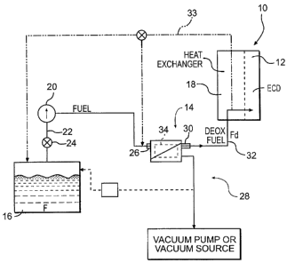
Figure 1 is a general schematic block diagram of an energy conversion
device (ECD) and an associated fuel system employing a fuel deoxygenator in
accordance with the present invention;
Figure 2A is an expanded perspective view of a deoxygenator system;
Figure 2B is an exploded view of a deoxygenator system;
Figure 2C is an expanded perspective view of a fuel plate assembly of the
deoxygenator system of Figure 2B;
Figure 3 is an expanded sectional view of a fuel plate assembly illustrating a
fuel channel and an oxygen-receiving channel;
Figure 4 is an expanded sectional view of the composite oxygen permeable
porous membrane; and
Figure 5 is an expanded sectional view of a non-planar composite oxygen
permeable porous membrane.
DETAILED DESCRIPTION OF THE PREFERRED EMBODIMENT
Figure 1 illustrates a general schematic view of a fuel system 10 for an
energy conversion device (ECD) 12. A deoxygenator system 14 receives liquid
fuel
F from a reservoir 16 such as a fuel tank. The fuel F is typically a
hydrocarbon
such as jet fuel. The ECD 12 may exist in a variety of forms in which the
fuel, at
some point prior to eventual use for processing, for combustion, or for some
form of
energy release, acquires sufficient heat to support autoxidation reactions and
coking
if dissolved oxygen is present to any significant extent in the fuel.
One form of the ECD 12 is a gas turbine engine, and particularly such
engines in aircraft. Typically, the fuel also serves as a coolant for one or
more sub-
systems in the aircraft and becomes heated as it is delivered to fuel
injectors
immediately prior to combustion.
A heat exchange section 18 represents a system through which the fuel
passes in a heat exchange relationship. It should be understood that the heat
exchange section 18 may be directly associated with the ECD 12 and/or
distributed
elsewhere in the larger system 10. The heat exchange system 18 may
alternatively
or additionally include a multiple of heat exchanges distributed throughout
the
system.
3
CA 02556207 2006-08-14
As generally understood, fuel F stored in the reservoir 16 normally contains
dissolved oxygen, possibly at a saturation level of 70 ppm. A fuel pump 20
draws
the fuel F from the reservoir 16. The fuel pump 20 conununicates with the
reservoir
16 via a fuel reservoir conduit 22 and a valve 24 to a fuel inlet 26 of the
deoxygenator system 14. The pressure applied by the fuel pump 20 assists in
circulating the fuel F through the deoxygenator system 14 and other portions
of the
fuel system 10. As the fuel F passes through the deoxygenator system 14,
oxygen is
selectively removed into a vacuum or sweep gas system 28. The sweep gas can be
any gas that is essentially free of oxygen.
The deoxygenated fuel Fd flows from a fuel outlet 30 of the deoxygenation
system 14 via a deoxygenated fuel conduit 32, to the heat exchange system 18
and to
the ECD 12 such as the fuel injectors of a gas turbine engine. A portion of
the
deoxygenated fuel may be recirculated, as represented by recirculation conduit
33 to
either the deoxygenation system 14 and/or the reservoir 16. It should be
understood
that although a particular component arrangement is disclosed in the
illustrated
embodiment, other arrangements will benefit from the instant invention.
Referring to Figure 2A, the deoxygenator system 14 preferably includes a
multiplicity of gas/fuel micro-channel assemblies 34 (Figure 2B). The
assemblies
34 include a composite oxygen permeable membrane 36 between a fuel channel 38
and an oxygen receiving vacuum or sweep gas channel 40 which is preferably a
mesh which permits the flow of nitrogen and/or another oxygen-free gas (Figure
3).
It should be understood that the channels may be of various shapes and
arrangements to provide a pressure differential, which maintains an oxygen
concentration differential across the membrane to deoxygenate the fuel.
The composite oxygen permeable membrane 36 preferably includes oxygen
permeable membranes, which allow dissolved oxygen (and other gases) to diffuse
through angstrom-size voids but exclude the larger fuel molecules, and
permeable
membranes which use a solution-diffusion mechanism to dissolve the oxygen
(and/or other gases) and allow it (or them) to diffuse through the membrane,
while
excluding the fuel. The family of Teflon AF which is an amorphous copolymer of
perfluoro-2,2-dimethyl-1,3-dioxole (PDD) often identified under the trademark
"Teflon AF" registered to E. I. DuPont de Nemours of Wilmington, Del., and the
4
CA 02556207 2006-08-14
family of Hyflon AD which is a copolymer of 2,2,4-trifluoro-5-trifluoromethoxy-
1,3- dioxole (TTD) registered to Solvay Solexis, Milan, Italy have proven to
provide
effective results for fuel deoxygenation. The Teflon AF 2400 and/or Teflon AF
1600
material is believed to use a solution-diffusion mechanism.
Referring to Figure 2B, one set of plates, which forms one micro-channel
assembly 34 of the deoxygenator system 14, includes a fuel plate assembly 44
sandwiched adjacent to the composite oxygen permeable membranes 36 which are
supported by a porous support 42 such as non-woven polyester. It should be
understood that the porous substrate, although schematically illustrated, may
take
various forms. Adjacent one or more assembly 34 is a separator plate 48. The
separator plate 48 prevents fuel from leaking across the predefined fuel
passages
defined by the fuel plate assemblies 34. The deoxygenation system 14,
irrespective
of the number of micro-channel assemblies 34, is sealed by an interface plate
46 and
an outer housing plate 50a, 50b, which respectively include the fuel inlet 26,
the
vacuum port 29, and the fuel outlet 30 (also illustrated in Figures 2A). The
outer
housing plates 50a, 50b are preferably attached together through a multitude
of
fasteners such as bolts or the like such that the micro-channel assemblies 34
are
sandwiched therebetween. The outer housing plates 50a, 50b are preferably
relatively rigid components which compress the micro-channel assemblies 34
such
that sealing between plates are maintained thereby. Although illustrated as
rectilinear in the illustrated embodiment, one of ordinary skill in the art
will
recognize that alternative shapes, sizes, or configurations are suitable and
within the
scope of the invention.
Each fuel plate assembly 44 defines a portion of the fuel channel 38 between
the inlet 26 and outlet 28. The vacuum port 29 (Figure 2A) is in communication
with
a vacuum port 29f (Figure 2B) through the interface plate 46 and the porous
support
42. Vacuum creates a partial pressure gradient within each of the porous
supports 42
to extract dissolved oxygen and other dissolved gases from the fuel channel 38
through the composite oxygen permeable membrane 36. The oxygen is expelled
through the vacuum port 29.
The specific quantity of micro-channel assemblies 34 are determined by
application-specific requirements, such as fuel type, fuel temperature, and
mass flow
5
CA 02556207 2006-08-14
demand from the engine. Further, different fuels containing differing amounts
of
dissolved oxygen may require differing amounts of deoxygenation to remove a
desired amount of dissolved oxygen.
Each fuel plate assembly 44 defines one fuel channel 38 (Figure 3) between
the inlet 26 and outlet 28 (Figure 2A). The configuration of the fuel channel
38 is
preferably defined to maximize fuel exposure to the composite oxygen permeable
membrane 36 in order to maximize the amount of dissolved oxygen removed from
the fuel. This may be accomplished by providing mixing and/or optimal flow
patterns for the fuel. The fuel channels 38 are formed to maximize the amount
of
area of the fuel in contact with the permeable membrane in order to maximize
the
amount of dissolved oxygen removed from the fuel. The fuel channels 38 are
preferably small enough that fuel is in contact with the composite oxygen
permeable
membrane 36 but also large enough so as to not restrict fuel flow.
Each fuel plate assembly 44 includes a first fuel plate 52, a second fuel
plate
54, and a fuel plate gasket 56 therebetween. It should be understood that the
fuel
plate assembly 44 disclosed in the illustrative embodiment illustrates only
two fuel
plates and a gasket for the sake of clarity, it should be understood that any
number of
plates may be located between the outer housing plates 50a, 50b. Preferably,
all of
the plates between the outer housing plates 50a, 50b are non-metallic.
Each fuel plate assembly 44 includes a first fuel plate 52, a second fuel
plate
54, and a fuel plate gasket 56 therebetween. The gasket 56 may be manufactured
of
a KAPTON film manufactured by E. I. du Pont de Nemours and Company of
- Delaware USA. It should be understood that the fuel plate assembly 44
disclosed in
the illustrative embodiment illustrates only two fuel plates and a gasket for
the sake
of clarity, it should be understood that any number of plate assemblies may be
located between the outer housing plates 50a, 50b.
The first fuel plate 52 and the second fuel plate 54 are preferably
manufactured of a non-metallic material such as a thermoplastic or a
polyphenylene
sulfide (PPS). It should be understood that other plastics that are compatible
with
fuel and are electrically conductive (to prevent static charge buildup) may
alternatively be utilized as well as materials which are machined rather than
molded.
6
CA 02556207 2006-08-14
The first fuel plate 52 and the second fuel plate 54 include flow impingement
elements 55 (Figures 2C and 3) which increase oxygen diffusivity. When the
fuel
plates 52, 54 are assembled together, the flow impingement elements 55 are
interleaved and alternate to provide the fuel channel 38 defined by the fuel
plates 52,
54 with an intricate 3-dimensional flow characteristics (Figure 3). In other
words,
the flow impingement elements 55 on each fuel plate 52, 54 extend above the
planar
surface of their respective fuel plates 52, 54. When the fuel plates 52, 54
are
assembled together with the gasket 56 to form the fuel plate assembly 44, the
flow
impingement elements 55 form a complete fuel channel 38 in which the flow
impingement elements 55 from adjacent fuel plates 52, 54 extend (Figure 3).
The flow impingement elements 55 enhance deoxygenation by increasing
transport of oxygen molecules to the oxygen permeable membrane surface, while
the non-metallic material minimizes weight and sharp edges which may otherwise
damage the oxygen permeable membranes 36. The flow impingement elements 55
of the deoxygenator system 14 enhance contact between fuel flow and the
composite
oxygen permeable membrane 36 to increase mass transport of dissolved oxygen.
Referring to Figure 3, fuel flowing through the fuel channel 38 is in contact
with the composite oxygen permeable membrane 36. Vacuum creates an oxygen
partial pressure differential between the inner walls of the fuel channel 38
and the
composite oxygen permeable membrane 36 which causes diffusion of oxygen
dissolved within the fuel to migrate through the porous support 42 which
supports
the membrane 36 and out of the deoxygenator system 14 through the oxygen-
receiving channel 40 separate from the fuel channel 38. For further
understanding
of other aspects of one membrane based fuel deoxygenator system and associated
components thereof, attention is directed to United States Patent No.
6,315,815
entitled Membrane based fuel deoxygenator; United States Patent No. 6,939,392
entitled System and method for thermal management and United States Patent No.
6,709,492 entitled PLANAR MEMBRANE DEOXYGENATOR which are assigned
to the assignee of the instant invention and which are hereby incorporated
herein in
their entirety.
Referring to Figure 4, the composite oxygen permeable membrane 36 is
formed from a multiple of layers. Preferably, the layers include a sealant
layer 60,
7
CA 02556207 2006-08-14
an oxygen permeability layer 62 and a porous backing layer 64. The layered
composite oxygen permeable membrane 36 maximizes the oxygen transfer rate and
mininlizes the fuel leakage rate to provide an efficient compromise based on
product
performance requirements. As the rate of fuel leakage through the membrane 36
is
significantly lower than that of oxygen, the relatively thin sealant layer 60
has a
dramatic impact in reducing the former without significantly affecting the
latter.
The porous backing layer 64 is preferably an asymmetric porous substrate
approximately two thousands of an inch thick. One such material is
polyetherimide
solution-cast by the method of phase inversion which provides skin pores on
the
order of approximately 40 nanometers such as that manufacture by Membrane
Technology and Research, Inc. of Menlo Park, CA USA.
The porous backing layer 64 supports the oxygen permeability layer 62 such
that the oxygen permeability layer 62 may be coated thereto and essentially
bridge
the skin pores thereof. The oxygen permeability layer 62 is preferably
approximately 1-2 microns thick and is preferably manufactured of a polymer
with
high oxygen permeability such as Teflon AF 2400.
The sealant layer 60 coats the oxygen permeability layer 62. The sealant
layer 60 is preferably less than 1 micron thick and is preferably manufactured
of an
oxygen-permeable polymer with lower Free Fractional Volume (FFV), such as
Teflon AF 1600, Hyflon AD, etc., which provides fuel-resistant properties to
the
adjacent fuel flow.
The composite oxygen permeable membrane 36 is located adjacent the
porous support 42 which provides stability to the composite oxygen permeable
membrane 36 when sandwiched into the multiple of gas/fuel micro-channel
assemblies 34 (Figure 2B). Also, the porous support 42 provides a cushion
between
the porous backing layer 64 and the vacuum mesh which defines the oxygen-
receiving channel 40 (Figure 3). It should be understood that various flow
through
layers such as mesh, a honeycomb structure or other gaseous transfer channel
structures may alternatively or additionally be utilized with the present
invention.
It should be understood that the composite oxygen permeable membrane 36
need not be a planar member and that various shapes of the porous backing
layer 64'
(Figure 5) may be coated with the sealant layer 60 and oxygen permeability
layer 62
8
CA 02556207 2006-08-14
to meet various packaging considerations; provide various flow characteristics
as
well as form various fuel channe138 components.
Applicant has validated the composite oxygen permeable membrane 36 of
the present invention experimentally as compared to conventional single layer
membranes. In particular, a Teflon AF 1600/Teflon AF 2400 composite oxygen
permeable membrane 36 as described above having a total thickness of
approximately 2 microns exhibited a 20% improvement in jet fuel deoxygenation
with only approximately 1/10 of the fuel leakage rate compared to an
approximately
4 micron thick Teflon AF 2400 membrane with essentially no signs of
performance
degradation over 1000 hours of continuous operation.
The foregoing description is exemplary rather than defined by the limitations
within. Many modifications and variations of the present invention are
possible in
light of the above teachings. The preferred embodiments of this invention have
been
disclosed, however, one of ordinary skill in the art would recognize that
certain
modifications would come within the scope of this invention. It is, therefore,
to be
understood that within the scope of the appended claims, the invention may be
practiced otherwise than as specifically described. For that reason the
following
claims should be studied to determine the true scope and content of this
invention.
9