Note: Descriptions are shown in the official language in which they were submitted.
CA 02556407 2006-08-14
1
WO 2005/078294 PCT/KR2005/000400
Description
Radial foil bearing
Technical Field
[1] The present invention relates to a radial foil bearing.
Background Art
[2] A bearing is generally classified into a rolling bearing (using a ball or
a roller), an
oilless bearing (using a lubricant material for a frictional operation), a
sliding bearing
(using an oil), a gas bearing, and a magnetic bearing (using magnetic force
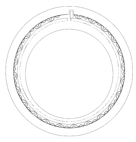
for a
contactless operation). The sliding bearing is divided into a hydrodynamic
sliding
bearing and a hydrostatic sliding bearing. The hydrodynamic sliding bearing
supports a
shaft using an oil pressure generated by a relative sliding motion. The
hydrostatic
sliding bearing supports a shaft using high-pressure oil supplied from the
exterior of
the bearing. The gas bearing is operated in the same manner as in the sliding
bearing,
excepting that gas is used instead of oil. The hydrostatic gas bearing is
supplied with a
compressed gas from the external source, and in the hydrodynamic gas bearing
the
pressure is generated by a relative sliding motion.
[3] The hydrodynamic gas bearing is widely used in the high-speed rotation ap-
plications, due to its low friction loss and unnecessity of liquid lubricant.
In particular,
it is used commonly in case of superspeed applications where the rolling
bearing
cannot be used for supporting and in case where a liquid lubricant cannot be
easily
used. The hydrodynamic gas bearing is categorized into a grooved bearing, a
tilting
pad bearing, and a foil bearing. The grooved bearing has a groove for
generating a
pressure, and exemplified by a spiral grooved bearing. In the case the
hydrodynamic
fluid-film tilt pad bearing, its working condition is very restricted and thus
a risk of
failure is increased disadvantageously if beyond the working condition. For
example,
since the rigidity thereof is rapidly decreased when above or below the design
criteria,
this bearing is very susceptible to impact, misalignment of a shaft, and
thermal de-
formation. In contrast, a foil bearing called a compliant hydrodynamic fluid-
film
bearing provide a very high performance, and a rapid progress has been made
recent
20 years. In addition, its adequate durability and stability has been
confirmed in the air
conditioning device of airplanes. In particular, it has been employed in a
high-speed
rotation machine such as a high-speed cryogenic turbo-compressor of 100,000
rpm.
This bearing can be used with minute liquid mixed and its flexibility and the
possibility
of lower price are their advantages. The foil bearing for airplanes has been
used mainly
since 1970 in the air cooling machine (ACM), which is a core component for
controlling the temperature and pressure inside the cabin in the environmental
control
system (ESC). This can be considered as a most suitable example of use. In
this ap-
2
WO 2005/078294 PCT/KR2005/000400
plication, the foil bearing does not contaminate the interior of the cabin
because it does
not have any oil system. Also, it has enabled a stable operation for a long
time, without
scheduled maintenance, as compared with a ball bearing. When failed,
advantageously
it does not lead to the failure of other turbo-components. The foil bearing
used in
Boeing 747 has been being operated more than 100,000 hours, without any
repair.
Disclosure of Invention
Technical Problem
[4] The foil bearing is generally divided into two types, i.e., a leaf type
and a bump
type. As shown in FIG. 1, in the leaf type foil bearing, plural vane-shaped
foils are
disposed in the direction of rotation with adjacent foils partially
overlapped, in which a
shaft is to be supported. As shown in FIG.2, the bump type foil bearing is
provided
with a single foil formed in its entirety, and the foil is supported by a
spring provided
around it. The leaf type foil bearing is suitable to the case where support
load is lower
and external impact is small, and the starting torque thereof is large
advantageously. In
contrast, the bump type brings out a small load when staring, and has a good
durability
and rigidity. However, since it has a complicated design and production
condition, and
in particular the stability thereof cannot be easily secured, only 2 or 3
companies hold
the technology worldwide. A bearing housing is provided with a bump foil
welded to
the inner side thereof, and the bump foil serves as a spring. Inwards thereof,
a top foil
is welded to the bearing housing and the top foil is practically contacted
with the shaft.
When the shaft rotates while drawing the air, the top foil and the bump foil
is deformed
such that a space for forming a fluid film is provided. In the foil bearing,
the ge-
ometrical structure for forming a fluid film is provided by the elastic
deformation of
the top foil. As the rotation frequency increase, the bump foil is pushed
outwards and
the shaft is off out of its center, thereby forming a space having the form of
a
converging wedge. At this time, using the deforming property of the top foil,
an
optimum structure capable of generating a suitable dynamic pressure can be
designed
without necessity of a complicated machining process. In addition, since
margin is
formed in a diametrical direction, advantageously, it can respond properly to
the
increase in the shaft diameter due to a high-speed rotation. These
characteristics rely
upon the thickness of the top foil and the bump structure supporting the top
foil. In
particular, the bump foil design is to determine whether the rigidity and
damping
required for a shafting can be provided or not. Therefore, the structure, the
thickness,
the height, the pitch, the number of the bump foil or the like is critical
factors to
determine the performance of a bump type foil bearing.
[5] Furthermore, a military-purpose bearing needs a capability of enduring a
higher
speed of rotation, and a severe environment and impact. In practice, these
requirements
CA 02556407 2006-08-14
3
WO 2005/078294 PCT/KR2005/000400
for a high speed, high-output and high efficiency BLDC motor can not be met by
a
common oil lubricant bearing. In addition, it must endure structurally and
adequately a
misalignment, heat and vibration. In order to obtain a maximum supporting
power for
these purposes, it is known to be beneficial that the bump foil is divided
along the axial
and rotational direction.
[6] The relevant patent is U.S. Patent Nos. 4,300,806, 5,915,841, 5,988,885,
4,465,384, 5,498,083, 5,584,582, 6,024,491, 6,190,048B1, 4,624,583, 3,893,733,
3,809,443, 4,178,046, 4,654,939, 4,005,914, 5,911,511, 5,534,723, 5,427,455,
and
5,866,518.
[7] The fundamental principle therefor has been patented in 1970s.
Modification to the
bump and top foils has been made in order to enhance the performance thereof.
The
U.S. Patent No. 5,866,518 discloses an attempt to develop a metallic dry
lubricant,
which can be applied a high-temperature applications and has a good adhesive
property.
Technical Solution
[8] The present invention relates to a bump type foil bearing, which has an
improved
performance, along with an improved productivity. Here, the performance means
a
supporting capacity and stability. Even though it has a good supporting
ability, it
cannot be readily employed without an appropriate stability. Also, even if it
provides
stability, it cannot be used in practice without an adequate supporting power.
FIGS. 1
and 2 shows a typical bearing, which has been commonly used. It is known that
the
bump type bearing has a supporting ability more than two times of that of the
leaf type,
but embraces a difficulty in securing stability and thus it has not been easy
to develop a
higher performance bearing.
[9] Furthermore, the invention relates to a bump type foil bearing, in which a
good
supporting power and stability can be secured, thereby providing a practical
bump type
foil bearing. Also, in the assembling of the bearing, the production rate is
disadvan-
tageously decreased due to the precision therefor. It has a structural
difficulty in that at
the elevated temperature (below 400 ° C), it must be adequately cooled
and thus the
whole system efficiency is degraded due to its cooling. At the ultrahigh
temperature
(below 800 ° C), a metallic lubricant must be used. Therefore, a
material having a good
adhesiveness must be developed in order to apply to the shaft. The
characteristic of the
lubricant is restricted and it causes a higher coating cost.
[10] Therefore, it is an object of the invention to improve the load
supporting capacity
while providing a high productivity, to provide a wide stable range so as to
be operated
with a higher stability at a high speed and high temperature. A further object
of the
invention is to enhance significantly its price and performance by using a
coating
material having a low adhesiveness.
CA 02556407 2006-08-14
CA 02556407 2006-08-14
4
WO 2005/078294 PCT/KR2005/000400
Description of Drawings
[11] Further objects and advantages of the invention can be more fully
understood from
the following detailed description taken in conjunction with the accompanying
drawings, in which:
[12] FIG. 1 shows a conventional leaf type radial foil bearing;
[13] FIG. 2 shows a conventional bump type radial foil bearing;
[14] FIG. 3 illustrates a radial foil bearing according to one embodiment of
the
invention; and
[15] FIG. 4 is a partially enlarged view of the radial foil bearing in FIG.3.
Best Mode
[16] The preferred embodiments of the present invention will be hereafter
described in
detail with reference to the accompanying drawings.
[17] A bump foil bearing according to one embodiment of the invention is a
general
type of bearing as shown in FIG. 2. The bump foil bearing of the invention
comprises a
top foil 1, a key 2, an inner bump foil 3, an outer bump foil 4, a bump sheet
5, a
housing 6, and a key groove 7.
[18] A fine gap exists between the shaft and the top foil 1. The surrounding
air or gas
serves as a lubricant oil. The top foil 1 exhibit another form rather than a
circle, due to
a pressure caused by the air flow generated from the rotation speed of the
shaft,
thereby further increasing its supporting force. Therefore, the rigidity of
the bump foils
3 and 4 and the thickness of the top foil 1 is of importance in determining
the
supporting force thereof. The behavior of the bump foil, which supports the
top foil 1,
determines the supporting power and stability. In addition, the performance
relies upon
the characteristics of the bump foils 3 and 4, which supports the top foil 1.
Therefore,
the present invention is intended to improve the performance and economical
efficiency by changing the structure of the bump foils 3 and 4 and the top
foil 1.
[19] The thickness of the top foil is made to be adequately thicker than the
conventional
case (0.1t in case of a bearing having a diameter of 60mm), such that a lathe
machining
and an inner diameter grinding can be performed. Therefore, the productivity
and the p
recision can be improved, and the shape of the bearing can be maintained at a
lower
rotation speed so that the frictional load can be alleviated to thereby reduce
its
wearing-out. Also, the high-temperature distortion can be decreased to thereby
reduce
the extent to be cooled. That is, the thickness of the top foil 1 is made to
become above
t >_ o.1 . D°v;
5
WO 2005/078294 PCT/KR2005/000400
( t: the thickness (mm), D: the diameter of the shaft (mm)), so that the
performance and
productivity therefore are enhanced. In addition, the inner diameter grinding
of the top
foil can be carried out. Therefore, in case where a metallic dry lubricant is
used, the
lubricant is sprayed in the inner diameter of the top foil using a plasma melt-
spraying
process, or the like and then ground, thereby avoiding a difficulty that a dry
lubricant
having a strong adhesiveness must be developed and sprayed in the outer
diameter of
the shaft, which is then ground. In this way, in order to achieve a high
performance by
making the top foil 2 thicker, a bump foil having a good characteristic in a
wide range
of load must be used together.
[20] The bump foils 3, 4 to be used together with the thicker top foil 1 can
transfer the
load uniformly to the top foil 1, even in case where the number thereof is low
(the
pitch thereof is large). Therefore, a high inner bump foil and a low inner
bump foil are
alternately disposed in such a way that the outer bump foil 4 is placed under
the high
inner bump foil 3 only. Consequently, it can have a three-step variation
effect of
rigidity, although a two-layer structure is used. As the bump foil is pressed,
the rigidity
does not vary linearly. That is, its structure is configured such that the
rigidity can be
increased in the form of an equation of the second or third degree, thereby
providing
stability in a wide range of rotation frequency.
[21 ] The inner bump 3 is formed of a higher one and a lower one alternately
arranged.
Thus, as the top foil is pressed, the rigidity is increased in a two-step
fashion. As the
top foil 1 is further pressed, the outer bump foil 4 is also pressed so that
the rigidity can
be increased in a three-step mode. The height of the outer bump foil 4 is
similar to the
lower one of the inner bump foil 3, and thus the thickness can be increased in
order to
increase the rigidity thereof.
Industrial Applicability
[22] As described above, the rigidity of the bump foils 3 and 4 is varied in a
three-step
way so that a high and low load can be supported. Due to the damping effect
caused by
the rigidity and the three-step unlinearity of rigidity, stability can be
secured, thereby
enabling the operation near the critical speed. The outer bump foil 4 is
disposed at the
larger pitch of the inner bump foil 3 so that the assembling precision can be
lowered
and the number of processes for assembling to the inner diameter of the
housing 6 can
be reduced, thereby enhancing productivity. Since the top foil has a thick
thickness, it
can be used up to the critical temperature, thereby improving the efficiency
thereof. It
is because the rigidity of the thick foil itself eliminates the high-
temperature distortion,
and thus cooling is not or less required. In consequence, the present
invention
overcomes the disadvantages in the prior art that the convention foil bearing
is
expensive, cannot be mass-produced, and cannot be easily applied to a high-
temperature application. Thus, according to the invention, the foil bearing
can be used
CA 02556407 2006-08-14
WO 2005/078294 PCT/KR2005/000400
widely in the industrial or civilian machines.
[23] Another advantage by the thicker top foil is that the top foil itself can
maintain its
shape, and thus the top foil and the bump foil does not need to be welded
directly to
the housing, thereby providing a simplified structure. The inner bump foil 3
and the
outer bump foil 4 are simply spot-welded to the bump sheet 5, which then only
has to
be assembled to the housing 6, along with the top foil 1. Simply, the key 2 is
welded
and fixed to the top foil 1 and the housing 6 has a key groove 7 in order to
prevent its
rotation. Consequently, the difficulty in the conventional one, where all the
components must be welded to the inner diameter of the housing 6, is overcome,
thereby increasing productivity.
[24] A strong point of the thicker top foil is that a small starting torque is
exerted. Since
the form of the bearing is maintained from the starting, due to a low friction
the load
when starting is low, thereby extending the service life of the bearing.
[25] While the present invention has been described with reference to the
particular i1-
lustrative embodiments, it is not to be restricted by the embodiments but only
by the
appended claims. It is to be appreciated that those skilled in the art can
change or
modify the embodiments without departing from the scope and spirit of the
present
invention.
CA 02556407 2006-08-14