Language selection

Search

Patent 2556470 Summary

Third-party information liability

Some of the information on this Web page has been provided by external sources. The Government of Canada is not responsible for the accuracy, reliability or currency of the information supplied by external sources. Users wishing to rely upon this information should consult directly with the source of the information. Content provided by external sources is not subject to official languages, privacy and accessibility requirements.

Claims and Abstract availability

Any discrepancies in the text and image of the Claims and Abstract are due to differing posting times. Text of the Claims and Abstract are posted:

  • At the time the application is open to public inspection;
  • At the time of issue of the patent (grant).
(12) Patent: (11) CA 2556470
(54) English Title: SINGLE PASS FUEL-FIRED FLUID HEATING/STORAGE DEVICE
(54) French Title: DISPOSITIF DE CHAUFFAGE/STOCKAGE DE LIQUIDE A COMBUSTION AVEC PASSAGE UNIQUE
Status: Deemed expired
Bibliographic Data
(51) International Patent Classification (IPC):
  • F24H 1/20 (2006.01)
  • F22B 7/12 (2006.01)
  • F24H 1/36 (2006.01)
  • F28D 1/04 (2006.01)
(72) Inventors :
  • MISSOUM, OZZIE (United States of America)
  • WELK, GREGORY M. (United States of America)
  • HANEY, JEFFREY M. (United States of America)
  • STEPHENS, PHILLIP W. (United States of America)
  • ZHANG, QIAN (United States of America)
(73) Owners :
  • RHEEM MANUFACTURING COMPANY (United States of America)
(71) Applicants :
  • RHEEM MANUFACTURING COMPANY (United States of America)
(74) Agent: BLAKE, CASSELS & GRAYDON LLP
(74) Associate agent:
(45) Issued: 2009-06-02
(22) Filed Date: 2006-08-21
(41) Open to Public Inspection: 2007-03-08
Examination requested: 2006-08-21
Availability of licence: N/A
(25) Language of filing: English

Patent Cooperation Treaty (PCT): No

(30) Application Priority Data:
Application No. Country/Territory Date
11/222,349 United States of America 2005-09-08

Abstracts

English Abstract

A fuel-fired water heater has a single pass condensing-type heat exchanger disposed within its water storage tank portion. The heat exchanger includes a primary non-condensing portion defined by a combustion chamber positioned in an upper interior portion of the tank and having a spaced series of vertical tubes depending therefrom. A secondary condensing portion of the heat exchanger is defined by a plenum having a top side connected to the bottom ends of the vertical tubes, and a bottom side from which a downwardly coiled flue tube depends. A fuel burner generates hot combustion gases that are sequentially flowed into the combustion chamber and then downwardly through the balance of the heat exchanger in a single pass.


French Abstract

Un chauffe-eau alimenté par combustible est doté d'un échangeur de chaleur-évaporateur à passe unique situé dans le réservoir d'eau. L'échangeur de chaleur se compose d'une première partie, sans évaporation, constituée d'une chambre de combustion située dans la partie supérieure du réservoir et de laquelle descendent un ensemble de tubes verticaux. La deuxième partie de l'échangeur de chaleur, avec évaporation, comporte un plenum dont la face supérieure est reliée l'extrémité inférieure des tubes verticaux, un tube de fumée spiralé descendant de sa partie inférieure. Un brûleur génère des gaz de combustion chauds qui circulent, en une seule passe, d'abord dans la chambre de combustion puis dans le reste de l'échangeur de chaleur.

Claims

Note: Claims are shown in the official language in which they were submitted.


WHAT IS CLAIMED IS:

1. A fuel-fired fluid heating apparatus comprising:
a tank for holding a fluid to be heated;
a single pass heat exchanger disposed in said tank and having:
a combustion chamber,
a plenum spaced apart from said combustion chamber in said
first direction,
a spaced plurality of first flue tubes longitudinally extending in
said first direction between, and interconnecting, said combustion
chamber and said plenum, and
a second flue tube coupled to said plenum and coiling away
therefrom in said first direction, said second flue tube having an outlet
portion exiting said tank; and
a combustion system operative to flow combustion gases
sequentially through said combustion chamber, said first flue tubes, said
plenum, and said second flue tube.
2. The fuel-fired fluid heating apparatus of Claim 1 wherein:
said fuel-fired fluid heating apparatus is a water heater.
3. The fuel-fired fluid heating apparatus of Claim 1 wherein:
said fuel-fired fluid heating apparatus is a commercial water heater.
4. The fuel-fired fluid heating apparatus of Claim 1 wherein:
said first direction extends downwardly.


-7-


5. The fuel-fired fluid heating apparatus of Claim 1 wherein:
said combustion system includes a fuel burner having an outlet
communicated with the interior of said combustion chamber.
6. The fuel-fired fluid heating apparatus of Claim 1 wherein:
said single pass heat exchanger is a condensing type heat exchanger.
7. The fuel-fired fluid heating apparatus of Claim 6 wherein:
said condensing type heat exchanger has a primary, non-condensing
portion defined by said combustion chamber and said first flue tubes, and
a secondary, condensing portion defined by said plenum and said second
flue tube.
8. The fuel-fired fluid heating apparatus of Claim 7 wherein:
said primary, non-condensing portion of said heat exchanger is
formed from a metal material, and
said secondary, condensing portion of said heat exchanger is
formed from a porcelainized metal material.
9. The fuel-fired fluid heating apparatus of Claim 7 wherein:
said single pass heat exchanger has a length extending in said first
direction, and
said primary, non-condensing portion of said heat exchanger has a
heat transfer rate per length substantially greater than the heat transfer
rate per length of said secondary, condensing portion of said heat
exchanger.


-8-


10. The fuel-fired fluid heating apparatus of Claim 1 wherein:
said single pass heat exchanger has a heat transfer efficiency of at
least 95 percent.
11. The fuel-fired fluid heating apparatus of Claim 7 wherein:
said tank has a fluid inlet disposed adjacent said secondary,
condensing portion of said heat exchanger.
12. The fuel-fired fluid heating apparatus of Claim 6 wherein, during
operation of said combustion system:
the temperature within said combustion chamber and said first flue
tubes is above the condensation temperature of said combustion gases.


-9-


13. A fuel-fired water heater comprising:
a tank for holding a quantity of water to be heated;
a single pass, condensing type heat exchanger disposed within the
interior of said tank and having:
a primary, non-condensing section defined by a combustion
chamber disposed in a top portion of said tank, and a spaced plurality of
primary flue tubes coupled to and longitudinally extending downwardly
from said combustion chamber, and
a secondary, condensing section defined by a plenum
connected to lower ends of said primary flue tubes, and a secondary flue
tube coupled to said plenum, coiling downwardly away from said plenum
through a lower interior portion of said tank, and having an outlet
portion exiting said tank;
a water inlet disposed on said tank for admitting water directly into
said lower interior portion of said tank; and
a fuel burner operative to flow combustion gases sequentially
through said combustion chamber, said primary flue tubes, said plenum
and said secondary flue tube.
14. The fuel-fired water heater of Claim 13 wherein:
said fuel-fired water heater is a commercial water heater.
15. The fuel-fired water heater of Claim 13 wherein:
said primary, non-condensing portion of said heat exchanger is
formed from either a coated or non-coated metal material, and
said secondary, condensing portion of said heat exchanger is
formed from an acid resistant, coated or non-coated metal material.


-10-


16. The fuel-fired water heater of Claim 13 wherein:
said primary, non-condensing portion of said heat exchanger has a
heat transfer rate per height substantially greater than the heat transfer
rate per height of said secondary, condensing portion of said heat
exchanger.
17. The fuel-fired water heater of Claim 13 wherein:
said a single pass, condensing type heat exchanger has a heat
transfer efficiency of at least 95 percent.


-11-

Description

Note: Descriptions are shown in the official language in which they were submitted.


CA 02556470 2006-08-21
Docket No.: RHWH-0129
SINGLE PASS FUEL-FIRED FLUID HEATING/STORAGE DEVICE
BACKGROUND OF THE INVENTION
The present invention generally relates to fuel-fired fluid heating
devices and, in a representatively illustrated embodiment thereof, more
particularly provides a fuel-fired water heater having a specially designed
~o single-pass condensing type heat exchanger incorporated therein.
Conventional fuel-fired water heaters are typically of a "single pass",
non-condensing configuration, meaning that the hot combustion gases
used to heat the tank-stored water are subjected to only a single pass
through a heat exchanger structure (usually a vertical flue) within the tank
before being discharged from the water heater to, for example, an
external vent structure, and that flue gas condensation does not occur to
any appreciable degree in the heat exchanger structure within the water
heater tank. In this conventional type of fuel-fired water heater, the
overall thermal efficiency is typically limited to about 80-85%. Various
2o proposals have been made to provide fuel-fired water heaters with
condensing type single-pass heat exchangers (i.e., in which flue gases
condense within the heat exchanger). However, previously proposed
single-pass condensing type heat exchange structures incorporated in
fuel-fired water heaters typically provide the water heaters with
maximum thermal efficiencies limited to the 85-90% range.
It would be desirable to provide a fuel-fired water heater with a
single pass heat exchanger having a heat transfer efficiency of at least
ninety five percent and preferably greater.

CA 02556470 2006-08-21
SUMMARY OF THE INVENTION
In carrying out principles of the present invention, in accordance
with a representative embodiment thereof, a fuel-fired fluid heating
s apparatus is provided which is representatively a water heater but could
alternatively be a variety of other types of fuel-fired fluid heating devices
without departing from principles of the present invention.
From a broad perspective, the fuel-fired fluid heating apparatus
includes a tank for holding a fluid to be heated, and a specially configured
~o single pass heat exchanger, preferably of a condensing type, disposed in
the interior of the tank. The heat exchanger includes a combustion
chamber, a plenum spaced apart from the combustion chamber in a first
direction, a spaced plurality of first flue tubes longitudinally extending in
the first direction between, and interconnecting, the combustion
chamber and the plenum, and a second flue tube coupled to the plenum
and coiling away therefrom in the first direction, the second flue tube
having an outlet portion exiting the tank. The fluid heating apparatus also
has a combustion system operative to flow combustion gases sequentially
through the combustion chamber, the first flue tubes, the plenum, and
2o the second flue tube.
In a preferred embodiment thereof, the apparatus is a fuel-fired
commercial water heater having a tank for holding a quantity of water to
be heated, and a single pass condensing type heat exchanger disposed
within the interior of the tank.
2s The heat exchanger has (1) a primary, non-condensing section
defined by a combustion chamber disposed in a top portion of the tank,
and a spaced plurality of primary flue tubes coupled to and longitudinally
extending downwardly from the combustion chamber, and (2) a
-2-

CA 02556470 2006-08-21
secondary, condensing section defined by a plenum connected to lower
ends of the primary flue tubes, and a secondary flue tube coupled to the
plenum, coiling downwardly away from the plenum through a lower
interior portion of the tank, and having an outlet portion exiting the tank.
s The fuel-fired water heater also has a water inlet disposed on the
tank for admitting water directly into the lower interior portion of the
tank, and a fuel burner operative to flow combustion gases seauentially
through the combustion chamber, the primary flue tubes, the plenum,
and the secondary flue tube.
~o According to other preferred aspects of the invention, (1) the
primary, non-condensing portion of the heat exchanger is formed from a
coated or non-coated metal material, and the secondary, condensing
portion of the heat exchanger is formed from an acid resistant, coated or
non-coated metal material, representatively a porcelainized metal
material (2) the primary, non-condensing portion of the heat exchanger
has a heat transfer rate per height substantially greater than the heat
transfer rate per height of the secondary, condensing portion of the heat
exchanger, and (3) and the single pass, condensing type heat exchanger
has a heat transfer efficiency of at least 95 percent.
BRIEF DESCRIPTION OF THE DRAWING
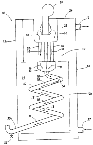
The single drawing figure schematically illustrates, in cross-sectional
form, a fuel-fired water heater incorporating therein a specially designed
single-pass condensing type heat exchanger embodying principles of the
present invention.
-3-

CA 02556470 2006-08-21
DETAILED DESCRIPTION
Schematically illustrated in cross-section in the accompanying single
drawing figure is a fuel-fired water heater 10, representatively a
commercial water heater, having a specially designed single pass
s condensing type heat exchanger 12 extending through the stored water
14 in its insulated tank portion 16. Tank 16, as illustrated, is provided with
a lower water inlet fitting 17 and an upper water discharge fitting 19.
During firing of the water heater 10, hot flue gases 18 from a burner 20 at
the top of the water heater are flowed through the heat exchanger 12 to
~o transfer combustion heat, with a thermal efficiency of 95% or above, to
the stored water 14.
The heat exchanger 12 has an upper, non-condensing primary
section 12a, and a lower, condensing secondary section 12b. Upper
section 12a includes a submerged combustion chamber 22 extending
15 downwardly into the water 14 from the top end 24 of the tank 16, and a
spaced series of vertical flue tubes 26 extending downwardly from the
bottom of the combustion chamber 22. Lower heat exchanger section
12b includes a collector plenum structure 28 connected to the bottom
ends of the vertical flue tubes 26. A coiled flue tube 30 extends
2o downwardly from the collector plenum 28 and exits a bottom portion of
the tank 16 as a flue and condensate discharge portion 30a having a
condensate drain fitting 32 connected thereto.
During firing of the water heater 10, flue gases 18 generated in the
submerged combustion chamber 22 flow seauentially therefrom in a
2s single pass downwardly through the flue tubes 26, into the plenum 28,
and then downwardly through the coiled tube 30 for discharge, with
condensate 34 formed in the lower heat exchanger section 12b,
outwardly through the tube discharge portion 30a.
-4-

CA 02556470 2006-08-21
In addition to the uniaue configuration of the heat exchanger 12,
other desirable features of the present invention are that the upstream,
non-condensing portion 12a of the heat exchanger 12 (1) is designed to
have an operating temperature (representatively about 1000 degrees F)
s higher than the flue gas condensation temperature, and (2) has a larger
cross-sectional heat transfer area per height than that of the lower,
condensing section 12b of the heat exchanger section. This eliminates the
need to form the upper heat exchanger section 12a from a more
expensive porcelainized metal material used to form the lower heat
~o exchanger section 12b to protect it from condensation-caused acidic
corrosion. Instead, the upper heat exchanger section 12a may be more
economically formed from a conventional coated or non-coated metal
material. The lower heat exchanger section 12b is formed from an acid
resistant coated or non-coated metal material, and is illustratively of a
~5 porcelainized metal construction.
In the illustrated single-pass condensing type heat exchanger
structure 12 approximately seventy percent of the total combustion heat
transferred to the stored water 14 comes from the upper primary, non-
condensing section 12a of the heat exchanger 12. The remaining
2o combustion heat transfer comes from the lower secondary, condensing
section 12b of the heat exchanger 12, the condensing of the combustion
gases 18 traversing the heat exchanger 12 being facilitated by the
placement of the secondary, condensing heat exchanger section 12b in
the water inlet zone of the water heater served by the bottom end inlet
25 fitting 17.
-5-

CA 02556470 2006-08-21
The heat exchanger 12, as illustrated, preferably has a vertical, down-
fired orientation, but could have other orientations, including a horizontal
orientation, if desired without departing from principles of the present
s invention.
The foregoing detailed description is to be clearly understood as
being given by way of illustration and example only, the spirit and scope
of the present invention being limited solely by the appended claims.
-6-

Representative Drawing
A single figure which represents the drawing illustrating the invention.
Administrative Status

For a clearer understanding of the status of the application/patent presented on this page, the site Disclaimer , as well as the definitions for Patent , Administrative Status , Maintenance Fee  and Payment History  should be consulted.

Administrative Status

Title Date
Forecasted Issue Date 2009-06-02
(22) Filed 2006-08-21
Examination Requested 2006-08-21
(41) Open to Public Inspection 2007-03-08
(45) Issued 2009-06-02
Deemed Expired 2020-08-31

Abandonment History

There is no abandonment history.

Payment History

Fee Type Anniversary Year Due Date Amount Paid Paid Date
Request for Examination $800.00 2006-08-21
Registration of a document - section 124 $100.00 2006-08-21
Application Fee $400.00 2006-08-21
Maintenance Fee - Application - New Act 2 2008-08-21 $100.00 2008-08-01
Final Fee $300.00 2009-03-16
Maintenance Fee - Patent - New Act 3 2009-08-21 $100.00 2009-08-04
Maintenance Fee - Patent - New Act 4 2010-08-23 $100.00 2010-07-30
Maintenance Fee - Patent - New Act 5 2011-08-22 $200.00 2011-08-01
Maintenance Fee - Patent - New Act 6 2012-08-21 $200.00 2012-08-17
Maintenance Fee - Patent - New Act 7 2013-08-21 $200.00 2013-08-19
Maintenance Fee - Patent - New Act 8 2014-08-21 $200.00 2014-08-18
Maintenance Fee - Patent - New Act 9 2015-08-21 $200.00 2015-08-17
Maintenance Fee - Patent - New Act 10 2016-08-22 $250.00 2016-08-15
Maintenance Fee - Patent - New Act 11 2017-08-21 $250.00 2017-08-14
Maintenance Fee - Patent - New Act 12 2018-08-21 $250.00 2018-08-20
Maintenance Fee - Patent - New Act 13 2019-08-21 $250.00 2019-08-16
Owners on Record

Note: Records showing the ownership history in alphabetical order.

Current Owners on Record
RHEEM MANUFACTURING COMPANY
Past Owners on Record
HANEY, JEFFREY M.
MISSOUM, OZZIE
STEPHENS, PHILLIP W.
WELK, GREGORY M.
ZHANG, QIAN
Past Owners that do not appear in the "Owners on Record" listing will appear in other documentation within the application.
Documents

To view selected files, please enter reCAPTCHA code :


To view images, click a link in the Document Description column. To download the documents, select one or more checkboxes in the first column and then click the "Download Selected in PDF format (Zip Archive)" or the "Download Selected as Single PDF" button.

List of published and non-published patent-specific documents on the CPD .

If you have any difficulty accessing content, you can call the Client Service Centre at 1-866-997-1936 or send them an e-mail at CIPO Client Service Centre.


Document
Description 
Date
(yyyy-mm-dd) 
Number of pages   Size of Image (KB) 
Abstract 2006-08-21 1 22
Description 2006-08-21 6 241
Claims 2006-08-21 5 133
Drawings 2006-08-21 1 20
Representative Drawing 2007-02-16 1 7
Cover Page 2007-02-28 2 44
Cover Page 2009-05-11 2 45
Prosecution-Amendment 2008-06-16 1 32
Assignment 2006-08-21 8 264
Prosecution-Amendment 2006-11-20 1 28
Prosecution-Amendment 2008-02-22 1 40
Correspondence 2009-03-16 2 51
Correspondence 2009-07-16 6 294
Correspondence 2009-08-12 1 13
Correspondence 2009-08-12 1 26
Returned mail 2014-05-02 2 68
Correspondence 2013-12-11 1 26
Correspondence 2014-01-17 1 23