Note: Descriptions are shown in the official language in which they were submitted.
CA 02556588 2007-12-27
TITLE: YARD HYDRANT WITH DRAIN PORT AIR LINE
BACKGROUND OF THE INVENTION
This invention is directed toward a yard hydrant, and
more specifically to a yard hydrant that flushes water out
of a valve body and standpipe.
Yard hydrants are well known in the art and have an
inlet valve connected to a water supply that is located
below the frost line in the ground. When a hydrant is shut
off, a drain port at the inlet valve is opened to allow
water in the hydrant to drain out. The problem with this
design is that ground water or other contaminants can enter
the yard hydrant through the same drain port, thus creating
an unacceptable cross-connection. Also, water may be
retained within the hydrant which could freeze, and lead to
a rupture. Accordingly, there is a need in the art for an
improved yard hydrant.
An objective of the present invention is to provide a
yard hydrant that allows the yard hydrant to be flushed.
This and other objectives will be apparent to those
skilled in the art.
SUMMARY OF THE INVENTION
A yard hydrant having a valve body coupled to an inlet
water pipe, a standpipe coupled to a valve body, and a head
casting coupled to the standpipe. The valve body has a
valve seat and a drain port. Disposed within the valve body
is a valve or plunger attached to an actuator rod or valve
stem that extends vertically through the standpipe and is
1
CA 02556588 2006-08-22
operatively conr.Lected to a lever or faucet handle. The head
casting has an inlet port, an outlet port and a conduit that
extends from the inlet port to the outlet port. Mounted to
the drain pipe is an air line that permits water within the
valve body and standpipe to be flushed with pressurized air.
BRIEF DESCRIPTION OF THE DRAWINGS
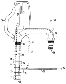
The figure is a side view of a yard hydrant.
DETAILED DESCRIPTION OF THE PREFERRED EMBODIMENTS
A yard hydrant 10 has a valve body 12, a valve seat 14,
a drain port or hole 16, an inlet 18 which is connected to a
source of pressurized water (not shown) and an outlet 20 at
its top. Connected at one end to the valve body 12 is a
standpipe 22 that extends vertically and is connected to a
head casting 24 at the opposite end.
The head casting 24 has an inlet 26 coupled to the
standpipe 22 and a discharge conduit or outlet 28 that
preferably extends outwardly from the head casting 24 and a
fluid conduit 30 that extends between the inlet 26 and the
outlet 28.
Disposed within the valve body 12 is a closure valve
plunger 32 that is connected to a valve stem or actuator rod
34 that extends from the closure valve 32 through the
standpipe 22 and is connected to an actuator device 36
attached to the head casting 24 such as a lever or handle.
Mounted adjacent to the drain port 16 is an air line
38. The air line 38 is mounted to the drain port 16 in any
conventional manner and extends from the drain port in any
direction including both vertical and horizontal directions.
End 40 of the air line 38 is adapted to connect with a
source of pressurized air (not shown).
2
CA 02556588 2006-08-22
When the closure valve 32 engages the valve seat 14 the
hydrant is in a closed position which prevents water from
flowing from the water source to the discharge conduit 28.
'When the closure valve 32 is in the closed position the
drain port 16 permits water to drain out of the pipe 22 and
into the ground or is retained within a portion of air line
38. When the cl.osure valve 32 is disengaged from the valve
seat 14, the closure valve 32 seals the drain port 16 and
water is permitted to enter the standpipe 22 and under
pressure flow toward the discharge conduit 28.
Occasionally, when the closure valve 32 is in the closed
position, some fluid may be retained within the valve body
12 and the standpipe. To flush this retained water from the
hydrant 10, pressurized air is supplied to the air line 38
such that as air flows from end 40, through drain port 16,
the retained water is forced toward and out of the discharge
conduit 28. In this manner, any water retained within the
hydrant may be flushed from the hydrant.
It will be appreciated by those skilled in the art that
other various modifications could be made to the device
without the parting from the spirit in scope of this
invention. All such modifications and changes fall within
the scope of the claims and are intended to be covered
thereby.
3