Note: Descriptions are shown in the official language in which they were submitted.
CA 02556630 2006-08-22
BACKGROUND OF THE INVENTION
1. Field of the Inventicm
The invention relates generally to the field of oil and gas production. More
specifically,
the present invention relates to a method of producing a shaped charge liner
from an injection
molding process.
2. Description of Related Art
Perforating guns are used for the purpose, among others, of making hydraulic
communication passages, called perforations, in wellbores drilled through
earth formations so
that predetermined zones of the earth formations can be hydraulically
connected to the wellbore.
Perforations are needed because wellbores are typically completed by coaxially
inserting a pipe
or casing into the wellbore, and the casing is retained in the wellbore by
pumping cement into the
annular space between the wellbore and the casing. The cemented casing is
provided in the
wellbore for the specific purpose of hydraulically isolating from each other
the various earth
formations penetrated by the wellbore.
Shaped charges known in the art for perforating wellbores are used in
conjunction with a
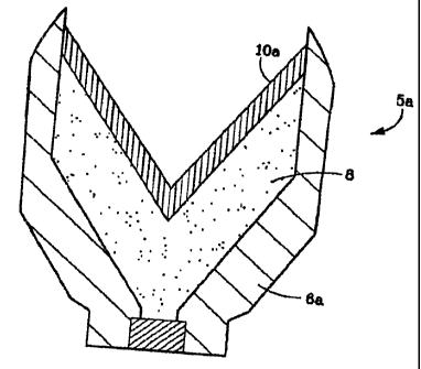
perforation gun. One embodiment of a traditional shaped charge 5 is
illustrated in Figure I . As
shown, shaped charge 5 includes a housing 6, a liner I0, and a quantity of
high explosive 8
inserted between the liner 10 and the housing 8 where the high explosive 8 is
usually HMX,
RDX PYX, or HNS. When the high explosive 8 is detonated, the force of the
detonation
collapses the liner 10 and ejects it from one end of the charge at very high
velocity in a pattern
called a "jet". The jet penetrates the casing, the cement and a quantity of
the formation.
i
CA 02556630 2006-08-22
Some of the traditional methods of producing shaped charge liners include
sintering and
cold working. Cold working involves mixing a powdered metal mix in a die and
compressing
the mixture under high pressure into a shaped liner. Typically, these liners
comprise a composite
of two or more different metals, where at least one of the powdered metals is
a heavy or higher
density metal, and at least one of the powdered metals acts as a binder or
matrix to bind the
heavy or higher density metal. Examples of heavy or higher density metals used
in the past to
form liners for shaped chargers have included tungsten, hafnium, copper, or
bismuth. Typically
the binders or matrix metals used comprise powdered lead, however powdered
bismuth has been
used as a binder or matrix m~°tal. While lead and bismuth are more
typically used as the binder
or matrix material for the powdered metal binder, other metals having high
ductility and
malleability can be used for the binder or matrix metal. Other metals which
have high ductility
and malleability and are suitable for use as a binder or matrix metal comprise
zinc, tin, uranium,
silver, gold, antimony, cobalt, copper, zinc alloys, tin alloys, nickel, and
palladium.
One of the problems associated with cold working a liner is a product having
inconsistent
I S densities. This is usually caused by migration of either the binder or the
heavy metal to a region
thereby producing a localized density variation. A lack of density homogeneity
curves the path
of the shaped charge jet that in turn shortens the length of the resulting
perforation. This is an
unwanted result since shorter perforations diminish hydrocarbon production.
Moreover, cold
worked liners have a limited shelf life since they are susceptible to
shrinkage thereby allowing
gaps to formed between the liners and the casing in which they are housed.
These liners also
tend to be somewhat brittle which leads to a fragile product.
Sintered liners necessarily involve a heating step of the liner, wherein the
applied heating
raises the liner temperature above the melting point of one or more of the
liner constituents. The
2
CA 02556630 2006-08-22
melted or softened constituent is typically what is known as the binder.
During the sintering step,
which is typically performed in a furnace, the metal powders coalesce while
their respective
grains increase in size. The sintering time and temperature will depend on
what metals are being
sintered.
The sintering process thus forms crystal grains thereby increasing the final
product
density while lowering the porosity. Typically sintering is performed in an
environment void of
oxygen or in a vacuum. However the ambient composition within a sintering
furnace may
change during the process, for example the initial stages of the process may
be performed within
a vacuum, with an inert gas added later. Moreover, the sintering temperature
may be adjusted
during the process, wherein the temperature may be raised or lowered during
sintering.
Prior to the sintering step the liner components can be cold worked as
described above,
injection molded, or otherwise formed into a unitary body. However the overall
dimensions of a
sintered liner can change up to 20% from before to after the sintering step.
Because this size
change can be difficult to predict or model, consistently producing sintered
shaped charge liners
that lie within dimensional tolerances can be challenging. Information
relevant to shaped charge
liners formed with powdered metals is addressed in Werner et al., U.S. Patent
No. 5,221,808,
Werner et al., U.S. Patent No. 5,413,048, Leidel, U.S. Patent No. 5,814,758,
Held et al. U.S.
Patent No. 4,613,370, Reese et al., U.S. Patent No. 5,656,791, and Reese et
al., U.S. Patent No.
5,567,906.
Therefore, there exist.. a need for a method of consistently manufacturing
shaped charge
liners, wherein the resulting; liners have a homogenous density, have
consistent properties
between liner lots, have a long shelf life, and are resistant to cracking.
3
CA 02556630 2006-08-22
BRIEF SUMMARY OF THE INVENTION
The present invention involves a method of forming a shaped charge liner
comprising,
creating a mixture of metal powder and a binder, molding the mixture into a
liner shape with an
injection molding device, and debinding the binder from the liner shape
thereby forming a liner.
The metal powder can be tungsten, uranium, hafnium, tantalum, nickel, copper,
molybdenum,
lead, bismuth, zinc, tin, silver, gold, antimony, cobalt, zinc alloys, tin
alloys, nickel, palladium,
coated metal particles. The metal powder can be chosen from these listed
metals singularly or
can come from combinations thereof.
The binder can be a polyolefine, an acrylic resin, a styrene resin, polyvinyl
chloride,
polyvinylidene chloride, polyamide, polyester, polyether, polyvinyl alcohol,
paraffin, higher fatty
acid, higher alcohol, higher fatty acid ester, higher fatty acid amide, wax-
polymer, acetyl based,
water soluble, agar water based and water soluble%ross-linked. The binder can
be chosen from
these listed binders singularly or can come from combinations thereof.
The step of debinding can include chemical debinding as well as thermal
debinding
1 S wherein the step of debinding; can comprise treating the liner shape with
a debinding agent. The
debinding agent can be water" nitric acid, organic solvents, as well as
combinations thereof. The
method can further include heating the liner shape thus removing additional
binder from the liner
shape.
The present method disclosed herein further comprises forming a shaped charge
with the
shaped charge liner, disposing the shaped charge within a perforating gun,
combining the
perforating gun with a perforating system, disposing the perforating gun
within a wellbore, and
detonating the shaped charge.
4
CA 02556630 2006-08-22
An alternate method of forming a shaped charge liner is disclosed herein
comprising,
combining powdered metal with organic binder to form a mixture, passing the
mixture through
an injection molding device, ejecting the mixture from the injection molding
device into a mold
thereby forming a liner shape in the mold, and debinding the binder from the
liner shape; wherein
the liner shape is sintered. The alternate method further comprises placing
the liner shape in a
vacuum. The alternate method of forming a shaped charge liner may also
comprise forming a
shaped charge with said shaped charge liner, disposing the shaped charge
within a perforating
gun, combining the perforating gun with a perforating system, disposing the
perforating gun
within a wellbore, and detonatiing the shaped charge.
A yet another alternative method of forming a shaped charge liner is disclosed
herein that
comprises forming a mixture by combining metal powder with a binder,
processing the mixture
with an injection molding apparatus, discharging the mixture into a mold
thereby forming the
liner, and removing the liner from the mold. In this alternative method of
forming a shaped
charge liner, the liner formed in the mold can be a "green product".
Also included with this disclosure is a method of forming a shaped charge
case. The
method of forming a shaped charge case comprises creating a mixture of metal
powder and a
binder, molding the mixtwe into a charge case shape with an injection molding
device, and
debinding the binder from the charge case shape to form a shaped charge case.
The metal
powder used in forming the shaped charge case can be the same as those used in
the liners further
including, stainless steel, carbon steel, and aluminum. The method of forming
a shaped charge
case can include a binder such as a polyolefin, an acrylic resin, a styrene
resin, polyvinyl
chloride, polyvinylidene chloride, polyamide, polyester, polyether, polyvinyl
alcohol, a paraffin,
a higher fatty acid, a higher alcohols, a higher fatty acid ester, a higher
fatty acid amide, a wax-
5
CA 02556630 2006-08-22
polymer, and combinations of these items. The method of forming a shaped
charge case can
further comprise chemical debinding and thermal debinding, where the step of
debinding further
comprises treating the liner shape with a debinding agent, The debinding agent
can be water,
nitric acid, organic solvents, or a combination thereof. The method of forming
a charge case can
further comprise heating the. charge case shape thereby removing remaining
binder from the
charge case shape. The char~;e case formed with the method disclosed herein
can further include
disposing the shaped charge within a perforating gun, combining the
perforating gun with a
perforating system, disposing the perforating gun within a wellbore, and
detonating the shaped
charge. Additionally, the case formed in the injection molding device can be a
green product.
BRIEF DESCRIPTION OF THE SEVERAL VIEWS OF THE DRAWING.
Figure 1 depicts a perspective cross sectional view of a shaped charge.
Figure 2 represents in flow chart form an embodiment of a liner forming
process.
Figure 3 illustrates a cross sectional view of an injection molding device.
Figure 4 portrays a side view of a liner shape.
Figure 5 is a cut away view of a perforating system with detonating shaped
charges.
Figure 6 is a cross sectional view of an embodiment of a shaped charge having
a liner
formed by the process described herein.
Figure 7 is an embodiment of a charge case forming process in flow chart form.
DETAILED DESCRIPTION OF THE INVENTION
The present disclosure involves a shaped charge liner and a method of making
the shaped
charge liner. The method disclosed herein involves a form of metal injection
molding wherein
metal powders are mixed wil:h binders and the mixture is subsequently injected
under pressure
6
CA 02556630 2006-08-22
into a mold. The binder is then removed during a de-binding process in order
to form the final
product.
With reference now to Figure 2, one embodiment of a method in accordance with
the
present invention is shown in flow chart form. Initially an amount of metal
powder is combined
with an amount of binder to form a mixture (step 100). The amount of metal
powder of the
mixture can range from about 20 % up to about 100 %, therefore the amount of
binder will range
from about 0 % to about 20 %. The particulate size of the powdered metal can
range from about
1 micron to in excess of TO microns. The powdered metal can be chosen from the
list
comprising: tungsten, uranium, hafnium, tantalum, nickel, copper, molybdenum,
lead, bismuth,
zinc, tin, silver, gold, antimony, cobalt, zinc alloys, tin alloys, nickel,
palladium, and
combinations thereof. Optionally, in place of the powdered metal, other
materials such as
ceramic, high density polymers, or cementitious materials can be substituted.
Another option is
to use a coated powder metal, where the coating typically comprises a metal
whose hardness is
less than that of the particle being coated.
The binder can be selected from the Iist comprising: polyolefines such as
polyethylene,
polypropylene, polystyrenes, polyvinyl chloride, polyetheylene carbonate,
polyethylene glycol,
microcrystalline wax, ethylene-vinyl acetate copolymer and the like; acrylic
resins such as
polymethyl methacrylate, polybutyl methacrylate; styrene resins such as
polystyrene; various
resins such as polyvinyl chloride, polyvinylidene chloride, polyamide,
polyester, polyether,
polyvinyl alcohol, copolymers of the above; various waxes; paraffin; higher
fatty acids (e.g.,
stearic acid); higher alcohols; higher fatty acid esters; higher fatty acid
amides. Other binder
possibilities include: acetyl based, water soluble, agar water based and water
soluble/cross-
linked; acetyl based binders comprise polyoxymethylene or polyacetyl with
small amounts of
7
CA 02556630 2006-08-22
polyolefin. The use of metal injection molded binders is well known and thus
the size of the
binder particulate can vary depending on the type of binder and/or the
application. Accordingly,
choosing a proper binder particulate size is within the scope of those skilled
in the art.
Upon forming the mi:Kture 22 of the metal powder and binder the mixture 22 is
placed
into an injection mold (step 102). One embodiment of the injection molding
device 12 is shown
in Figure 3. As shown in this embodiment of the injection molding device 12,
both the powder
18 and the binder 20 are directed through respective dispensers 14 to a chute
16, where the chute
in turn guides the mixture 22 into the injection molding device 12. The
mixture 22 can be
formed within the chute 16, the injection molding device 12, or alternatively,
the mixture 22 can
be formed prior to being directed into the chute 16. Once inside the injection
molding device 12,
the mixture 22 is within the p~lenum 26 of the injection molding device 12.
Rotation of an auger
24 disposed within the plenum 26 agitates the mixture thereby insuring a
uniformity of the
mixing of the binder and powder. The auger action also directs the mixture
towards an exit port
27 disposed on the side of the injection molding device 12 distal from the
chute 16. Moreover,
the auger 24 provides a source of pressure for urging the mixed and homogenous
mixture 22
from within the plenum 2b through the exit port 27 and into the inner confines
of a mold 28. As
is known, urging the mixture 22 into the mold 28 under pressure thereby can
form a liner shape
30 having the constituents of the mixture 22 (step 104).
One embodiment of a liner shape 30 is shown in Figure 4. It should be pointed
out that
this liner has but one of the possible shapes that could be formed from the
mixture 22 described
herein. With regards to an actual liner 10 made in accordance with the method
and process
described herein, any liner shape could be formed with this process. Shapes
such as conical
s
CA 02556630 2006-08-22
frusto-conical, triangular, tulip and trumpet shape, and parabolic shapes, to
name but a few, are
considered within the scope and purview of the present invention.
Upon removal of the liner shape 30 from the mold 28 the process of de-binding
the binder
is undertaken. This can be done both chemically, i.e. with solvents or
liquids, and thermally by
heating the liner shape. It is preferred that the first step of de-binding
occurs with a debinding
liquid or solvent (step I 06). This step involves chemically dissolving the
organic binder with the
de-binding liquid. Debinding can occur at atmosphere or under vacuum. The
debinding
solutions for use with the present method include water, nitric acid, and
other organic solvents.
However any suitable debin<ling solution can be used with the present method
and skilled
IO artisans are capable of choosing an appropriate debinding solution. During
debinding, the liner
shape 30 can be sprayed with l;he de-binding liquid or placed in a bath of de-
binding solution.
After the liner shape 30 is processed with the liquid de-binding solution, the
remaining
binder is removed during a thermal de-binding process (step 108). The thermal
de-binding
process involves placing the liner shape into a heated unit, such as a
furnace, where it is heated at
temperature for a period of time. With regard to the de-binding temperature,
it should be
sufficient to cause it to melt any remaining binder within the liner that
remains after the chemical
de-binding step of step 106 and yet be low enough to not exceed the melting
point of a metal
powder used as part of the liner constituency. It is believed as well within
the capabilities of
those skilled in the art to determine a proper temperature and corresponding
heating time to
accomplish this process. It is should be pointed that with regard to the
process described herein
the final step of forming a liner l0a is the de-binding process. Unlike many
traditional metal
injection molding processes, a sintering process is typically implemented
after the debinding
step. Thus although the present method does not include a step of sintering,
the advantages of a
9
CA 02556630 2006-08-22
forming a homogenous liner ll0a whose density is substantially consistent
along its length can be
realized by the unique process disclosed herein. Moreover, without the added
sintering step, the
final product will have dimensions substantially the same as that of the liner
shape 30. Other
advantages afforded by the present method are that liners formed in subsequent
moldings or lots
will have consistent characteristics and properties. Also, the present method
provides liners have
an enhanced shelf life and rt;duces the susceptibility of the liners to the
cracking problems of
liners formed from prior art miethods.
As is known, a green part is the intermediate product taken from an injection
mold prior
to the de-binding process. With regard to the present disclosure, the green
part is shown in
Figure 4 as a shaped liner 30. In an alternative process and an alternative
apparatus, the green
part shape liner 30 could be used as the final product liner in a shape charge
Sa. Accordingly
instead of a liner that had its binder removed during a de-binding process
(step 106, step 108), in
an alternative embodiment the shaped charge would have a shaped liner 30 for
use as its liner.
One of the advantages of using a green part is that the issue of shrinkage
during subsequent
heating is removed. Accordingly the size of the mold 28 could be more accurate
in conforming
to the required size of the final product.
With reference now to Figure 5 one embodiment of the final product of the
present
disclosure is shown combined with a perforating system 32. The perforating
system 32
comprises a perforating gun .'36 disposed within a wellbore 42 by a wireline
44. As shown, the
surface end of the wireline 44 is in communication with a field truck 34. The
field truck 34 can
provide not only a lowering and raising means, but also the firing controls
for detonation of the
shaped charges of the perforating gun 36. With regard to this embodiment, the
liner l0a is made
in accordance with the disclosure herein is combined with a shaped charge Sa
that is disposed in
CA 02556630 2006-08-22
the perforating gun 36. Also shown are perforating jets 38, created by
detonation of each shaped
charge Sa thereby creating perforations 41 within the formation 40 surrounding
the wellbore 42.
Accordingly the implementation of the more homogenous and uniform liner
material made in
accordance with the methodl described herein is capable of creating longer and
straighter
perforations 41 into the accorr~panying formation 40.
It should be pointed out that the shaped charge Sa of Figure 6 has essentially
the same
configuration as the shaped charge 5 of Figure 1. Figure 6 is provided for
clarity and to illustrate
that shaped charges having the traditional configuration can be formed with a
liner l0a made in
accordance with the disclosure provided herein. Moreover, the formation
process disclosed
herein can also be applicable for the forming of charge casings or housings.
As seen in Figure 7,
a process similar to that of Figure 2 is illustrated. With regard to the
process of Figure 7, a
mixture of metal powder and binder is formed (step 200). The metal powder used
in the
formation of a charge casing includes the metals used in the liner formation
and further
comprises steel such as carbon steel and stainless steel and other metals
including money
inconel, as well as aluminum.
Also similar to the process of forming a liner, after mixing the shaped charge
casing
components, the mixture is directed to an injection mold (step 202). Moreover,
the injection
mold can be the same as or substantially similar to the injection molding
device 12 of Figure 3.
The mixture can be formed prior to being placed in the injection molding
device or can be
formed while in the injection molding device. Steps 204, 206, and 208 of
Figure 7 are
substantially similar to the corresponding steps 104, 106, and 108 of Figure
2. One difference
however between formation of the charge case and liner is that the charge case
forming step (step
204) would require a mold having a charge case configuration instead of a
liner shaped mold.
1~
CA 02556630 2006-08-22
Also similarly, the present method can involve producing an injection molded
charge case
without a de-binding step thereby producing a "green part" charge case.
Optionally, the process
of forming the charge case could include a sintering step as above described.
As previously
noted, sintering involves heating the composition to above the melting point
of one or more of
the constituents of the final product. While the sintering temperature and
time of sintering
depends on the constituent rr.~etals and their respective amounts, it is
within the scope of those
skilled in the art to determine an appropriate sintering temperature, time, as
well as other furnace
conditions, such as pressure and ambient components.
The present invention described herein, therefore, is well adapted to carry
out the objects
and attain the ends and advantages mentioned, as well as others inherent
therein, While a
presently preferred embodiment of the invention has been given for purposes of
disclosure,
numerous changes exist in thc~ details of procedures for accomplishing the
desired results. These
and other similar modifications will readily suggest themselves to those
skilled in the art, and are
intended to be encompassed within the spirit of the present invention
disclosed herein and the
scope of the appended claims.
I2