Language selection

Search

Patent 2556691 Summary

Third-party information liability

Some of the information on this Web page has been provided by external sources. The Government of Canada is not responsible for the accuracy, reliability or currency of the information supplied by external sources. Users wishing to rely upon this information should consult directly with the source of the information. Content provided by external sources is not subject to official languages, privacy and accessibility requirements.

Claims and Abstract availability

Any discrepancies in the text and image of the Claims and Abstract are due to differing posting times. Text of the Claims and Abstract are posted:

  • At the time the application is open to public inspection;
  • At the time of issue of the patent (grant).
(12) Patent: (11) CA 2556691
(54) English Title: CONTAINER EXHIBITING IMPROVED TOP LOAD PERFORMANCE
(54) French Title: RECIPIENT A REMPLISSAGE PAR LE HAUT AMELIORE
Status: Term Expired - Post Grant Beyond Limit
Bibliographic Data
(51) International Patent Classification (IPC):
  • B65D 01/02 (2006.01)
(72) Inventors :
  • KAMINENI, SATYA (United States of America)
  • MOONEY, MICHAEL (United States of America)
(73) Owners :
  • PLASTIPAK PACKAGING, INC.
(71) Applicants :
  • PLASTIPAK PACKAGING, INC. (United States of America)
(74) Agent: GOWLING WLG (CANADA) LLP
(74) Associate agent:
(45) Issued: 2012-08-21
(86) PCT Filing Date: 2003-11-05
(87) Open to Public Inspection: 2004-09-23
Examination requested: 2008-10-31
Availability of licence: N/A
Dedicated to the Public: N/A
(25) Language of filing: English

Patent Cooperation Treaty (PCT): Yes
(86) PCT Filing Number: PCT/US2003/035337
(87) International Publication Number: US2003035337
(85) National Entry: 2006-08-16

(30) Application Priority Data:
Application No. Country/Territory Date
10/387,242 (United States of America) 2003-03-12

Abstracts

English Abstract


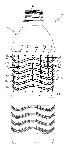
A plastic container (10) that exhibits an optimal ratio of hoop strength to
top load strength includes a finish portion (12) and generally cylindrical
main body portion (14). The main body portion includes a sidewall (16) that
has a first plurality of generally vertical ribs (18, 20, 21, 24) defined
therein. In addition, a second plurality of generally horizontal wave (26, 28,
30, 32, 34, 36) shaped ribs is defined in the sidewall. The generally
horizontal wave shaped ribs intersect with the generally vertical ribs,
thereby imparting enhanced strength characteristics to the container (10).


French Abstract

L'invention concerne un récipient en plastique (10) présentant un rapport optimal de la résistance annulaire à la résistance au remplissage par le haut, qui comprend une section de goulot (12) et une section de corps principal, de manière générale cylindrique (14). La section de corps principal comprend une paroi latérale (16) présentant une première pluralité de nervures (18, 20, 21, 24), de manière générale verticales, définies en cela. En outre, une seconde pluralité de nervures (26, 28, 30, 32, 34, 36) sous forme d'ondulations, de manière générale horizontales, sont définies dans la paroi latérale. Les nervures sous forme d'ondulations, de manière générale horizontales, croisent les nervures, de manière générale verticales, conférant ainsi au récipient (10), de meilleures caractéristiques de résistance.

Claims

Note: Claims are shown in the official language in which they were submitted.


CLAIMS
1. A plastic container, comprising:
a finish portion; and
a generally cylindrical main body portion, said main body portion comprising a
sidewall having a plurality of generally vertical ribs defined therein
parallel to the
revolution axis of the cylindrical main body portion, the vertical ribs being
concave, said
sidewall further having a plurality of generally horizontal wave shaped ribs
defined
therein, at least one of said generally horizontal wave shaped ribs having an
amplitude
that is within a range of about 4.5 percent to about 30 percent of its
wavelength, and at
least one of said generally vertical ribs intersecting with more than one of
said generally
horizontal wave shaped ribs.
2. A plastic container according to claim 1, wherein said container is
fabricated from
a plastic material comprising polyethylene terephthalate.
3. A plastic container according to claim 1, wherein said plurality of
generally
vertical ribs comprises at least one rib that is inwardly oriented.
4. A plastic container according to claim 1, wherein said plurality of
generally
horizontal wave shaped ribs comprises at least one rib that is inwardly
oriented.
5. A plastic container according to claim 1, wherein said plurality of
generally
horizontal wave shaped ribs comprises a plurality of wave shaped ribs that
extend
generally parallel to each other.
6. A plastic container according to claim 1, wherein said generally
horizontal, wave
shaped ribs are shaped so as to have a common amplitude and a common
wavelength.
6

7. A plastic container according to claim 6, wherein said sidewall has an
outer
circumference, and said wavelength of said generally horizontal wave shaped
ribs is
within a range of about 6 percent to about 40 percent of said outer
circumference.
8. A plastic container according to claim 1, wherein said at least one
generally
vertical rib intersects said generally horizontal wave shaped ribs at a
location of
maximum amplitude of each intersected horizontal wave shaped rib.
9. A plastic container according to claim 1, wherein said at least one
generally
vertical rib intersects said generally horizontal wave shaped ribs at a
location of
minimum amplitude of each intersected horizontal wave shaped rib.
10. A plastic container according to claim 1, wherein more than one of said
generally
vertical ribs intersect more than one of said generally horizontal wave shaped
ribs, and
each intersected horizontal wave shaped rib is intersected within each
wavelength.
7

Description

Note: Descriptions are shown in the official language in which they were submitted.


CA 02556691 2006-08-16
WO 2004/080828 PCT/US2003/035337
s CONTAINER EXHIBITING IMPROVED TOP LOAD PERFORMANCE
BACKGROUND OF THE INVENTION
1. Field of the Invention
This invention relates generally to the field of consumer packaging. More
specifically, this invention relates to plastic containers of the type that
are used to package
consumer beverages, and the strength characteristics of such plastic
containers.
2. Description of the Related Technology
Plastic containers are in wide use commercially throughout the world for
packaging
liquids of all types, including consumer beverages. The most common type of
plastic
1 s container that is used for packaging, for example, soft drinks, is
fabricated from polyethylene
terephthalate (PET) and is molded into a desired shape using a blowmolding
process that is
well known in the industry.
In the design of such containers, a number of factors are ordinarily
considered. The
container must be chemically resistant and should be shaped to avoid
concentration of stress
that result in unwanted failure. In addition, the container must be strong
enough to endure the
packaging process and subsequent handling during the gross packaging, shipping
and retail
display stages.
~ne type of strength that plastic containers are regularly evaluated for it is
that of top
load strength. Top load strength involves resistance to failure, typically
sidewall buckling,
2s when a vertical force is exerted onto the top of the container. Such
vertical force is exerted
onto the container during the filling process and when the closure is
installed onto the
container. In addition, a great deal of vertical force may be exerted onto
filled containers
when cases of the containers are stacked during shipping. Another type of
strength that is

CA 02556691 2006-08-16
WO 2004/080828 PCT/US2003/035337
regularly evaluated in the design of plastic containers is hoop strength. Hoop
strength is the
resistance provided by the container against the tendency of the container
sidewall to bow
outwardly or deflect inwardly when the contents of the container are under
pressurization or
when external forces are applied to the outside of the container, which of
course is a common
scenario in the packaging and transportation of carbonated soft drinks.
It is generally known in the industry that circumferential reinforcement such
as
ribbing tends to increase hoop strength, and that vertical reinforcement has a
favorable efFect
on top load strength. However, it should be understood that there is a to
economic
disincentive to provide any more reinforcement to a plastic container design
than is
absolutely necessary, because increased reinforcement tends to make the
container heavier
and thus more expensive to manufacture. A need exists, then, for a plastic
container design
that optimizes hoop strength and top load strength while minimizing the amount
of plastic
material that is necessary to fabricate the container.
SUMMARY ~F TIIE INVENTI~N
Accordingly, it is an object of the invention to provide a plastic container
design that
optimizes hoop strength and top load strength wlule minmizing the amount of
plastic
material that is necessary to fabricate the container.
In order to achieve the above and other objects of the invention, a plastic
container
that is constructed according to a first aspect of the invention includes a
finish portion9 and a
generally cylindrical main body portion, said main body portion comprising a
sidewall having
a first plurality of generally vertical ribs defined therein, the sidewall
further having a second
plurality of generally horizontal wave shaped ribs defined therein, at least
one of the generally
horizontal wave shaped ribs intersecting with at least one of the generally
vertical ribs,
whereby enhanced strength characteristics are imparted to the container.
These and various other advantages and features of novelty that characterize
the
invention are pointed out with particularity in the claims annexed hereto and
forming a part
' hereof. However, for a better understanding of the invention, its
advantages, and the objects
2

CA 02556691 2006-08-16
WO 2004/080828 PCT/US2003/035337
obtained by its use, reference should be made to the drawings which form a
further part
hereof, and to the accompanying descriptive matter,,in which there is
illustrated and described
a preferred embodiment of the invention.
BRIEF DESCRIPTION OF THE DRAWINGS
FIGURE 1 is a side elevational view of a plastic container that is constructed
according to a preferred embodiment of the invention;
FIGURE 2 is a cross-sectional view taken along lines 2-2 in FIGURE l;
FIGURE 3 is a cross-sectional view taken along blinds 3-3 in FIGURE l; and
FIGURE 4 is a diagrammatical depiction of one of the wave-shaped ribs with the
circumference of the container represented along the x-axis.
DETAILED DESC PTION OF THE PREFE D EI~IBODII~IENT(S)
Referring now to the drawings, wherein like reference numerals designate
corresponding structure throughout the views, and referring in particular to
FIGURE l, a
plastic container 10 that is constructed according to a preferred embodiment
of the invention
in eludes a fin1S11 portion 12 and a generally cylindrical main body portion
14~ having an outer
sidewall 16. Preferably, plastic container 10 is fabricated from a plastic
material such as
. polyethylene terephthalate. As may be seen in FIGURE 1, body portion 14 has
a first
plurality of generally vertical ribs 18, 20, 22, 24 defined therein. Vertical
ribs 18, 20, 22, 24,
as shown in the cross-sectional view provided in FIGURE 3, are substantially
concave,
having a radius of depth R~, and extend generally radially inwardly toward the
center axis of
the container 10. The vertical ribs are preferably parallel to each other and
evenly spaced
from each other over the outer circumference of the main body portion 14 of
the container 10.
As may further be seen in FIGURE 1, the sidewall 16 further has a second
plurality of
generally horizontal wave shaped ribs 26, 28, 30, 32, 34, 36 defined therein.
The generally
horizontal wave shaped ribs 26, 28, 30, 32, 34, 36 preferably extend so as to
be parallel with
each other and are substantially evenly spaced from each other. It follows,
then, that each of

CA 02556691 2006-08-16
WO 2004/080828 PCT/US2003/035337
the wave shaped ribs has a common amplitude A and wavelength with each of the
other wave
shaped ribs, with the amplitude A being defined as the peak to peak vertical
distance between
the uppermost point of the wave crest to the lowermost point of the adjacent
wave trough and
the wavelength being defined as the circumferential peak to peak distance
traveled by the rib
from wave crest to wave crest. Each horizontal wave shaped rib is
substantially concave,
having a radius of depth R,, and extending inwardly toward the center axis of
the container
10. As may be seen in FIGURE l, at least one of the generally horizontal wave
shaped ribs
intersects with at least one of said generally vertical ribs, whereby enhanced
strength
characteristics are imparted to the container.
In the preferred embodiment, it will be seen that each of the generally
horizontal wave
shaped ribs 26, 28, 30, 32, 34, 36 intersects with each of the 16 vertical
ribs. Preferably, a
plurality, and more preferably at least three of the vertical ribs intersect
each wave shaped rib
within each wavelength. According to one important aspect of the invention,
the location or
placement of the vertical ribs is harmonized with respect to the waveform of
at least one of
the horizontal ribs. In the preferred embodiment, the vertical ribs 18, 20,
22, 24 will intersect
each of the generally horizontal wave shaped ribs 26, 28, 30, 32, 34, 36 in a
repeating pattern
such that each of the vertical ribs 18 intersects each wave shaped rib at the
lowermost point of
the wave trough, and so that each of the vertical ribs 20 intersects each wave
shaped rib at a
median location between the wave trough and an adjacent wave peak. Also, each
vertical rib
22 will intersect each wave shaped rib at the wave peak and each vertical rib
24 will intersect
each wave shaped rib at a median location between the wave peak and the next
wave trough.
Accordingly, at least one of the generally vertical ribs 18, 20, 22, 24
intersects at least one of
the generally horizontal wave shaped ribs 26, 28, 30, 32, 34, 36 at a location
of maximum
amplitude of the wave shaped rib, and another one of the generally vertical
ribs intersects the
horizontal wave shaped rib at a location of minimum amplitude. This is
believed to
maximize both the hoop strength and top load strength that is achievable by
the structure.
As may be visualized in FIGURE 1, sidewall 16 of the generally cylindrical
main
body portion 14 has an outer circumference. As is shown in FIGURE 4, which is
a
diagrammatical depiction of one of the wave-shaped ribs with the circumference
of the
4

CA 02556691 2006-08-16
WO 2004/080828 PCT/US2003/035337
container represented along the x-axis, each wave-shaped rib preferably has a
repeating
wavelength ~, and a common amplitude A. An angle A is defined by a triangle,
two legs of
which are equal to the amplitude A and one-half the wavelength ~,. Preferably,
the amplitude
A of the wave shaped ribs is within a range of about 4.5 percent to about 30
percent of the
wavelength ~,, which corresponds to angle 8 being within a range of about 5
degrees to about
30 degrees. The wavelength ~, should preferably be about 6 percent to about 40
percent of the
outer circumference of the container.
It is to be understood, however, that even though numerous characteristics and
advantages of the present invention have been set forth in the foregoing
description, together
with details of the structure and function of the invention, the disclosure is
illustrative only,
and changes may be made in detail, especially in matters of shape, size and
arrangement of
parts within the principles of the invention to the full extent indicated by
the broad general
meaning of the terms in which the appended claims axe expressed.
5

Representative Drawing
A single figure which represents the drawing illustrating the invention.
Administrative Status

2024-08-01:As part of the Next Generation Patents (NGP) transition, the Canadian Patents Database (CPD) now contains a more detailed Event History, which replicates the Event Log of our new back-office solution.

Please note that "Inactive:" events refers to events no longer in use in our new back-office solution.

For a clearer understanding of the status of the application/patent presented on this page, the site Disclaimer , as well as the definitions for Patent , Event History , Maintenance Fee  and Payment History  should be consulted.

Event History

Description Date
Inactive: Expired (new Act pat) 2023-11-06
Common Representative Appointed 2019-10-30
Change of Address or Method of Correspondence Request Received 2018-06-11
Letter Sent 2014-07-22
Inactive: Multiple transfers 2014-06-27
Inactive: Office letter 2014-05-21
Inactive: Single transfer 2014-04-24
Grant by Issuance 2012-08-21
Inactive: Cover page published 2012-08-20
Pre-grant 2012-06-11
Inactive: Final fee received 2012-06-11
Notice of Allowance is Issued 2011-12-13
Letter Sent 2011-12-13
Notice of Allowance is Issued 2011-12-13
Inactive: Approved for allowance (AFA) 2011-12-08
Amendment Received - Voluntary Amendment 2011-07-28
Inactive: S.30(2) Rules - Examiner requisition 2011-02-07
Amendment Received - Voluntary Amendment 2010-10-06
Inactive: S.30(2) Rules - Examiner requisition 2010-04-06
Amendment Received - Voluntary Amendment 2009-09-28
Amendment Received - Voluntary Amendment 2009-08-28
Letter Sent 2008-12-10
All Requirements for Examination Determined Compliant 2008-10-31
Request for Examination Requirements Determined Compliant 2008-10-31
Request for Examination Received 2008-10-31
Letter Sent 2007-01-30
Inactive: Courtesy letter - Evidence 2007-01-09
Correct Applicant Requirements Determined Compliant 2007-01-08
Inactive: Notice - National entry - No RFE 2007-01-08
Inactive: Single transfer 2007-01-05
Inactive: Courtesy letter - Evidence 2006-10-17
Inactive: Cover page published 2006-10-16
Inactive: Notice - National entry - No RFE 2006-10-10
Application Received - PCT 2006-09-19
National Entry Requirements Determined Compliant 2006-08-16
Application Published (Open to Public Inspection) 2004-09-23

Abandonment History

There is no abandonment history.

Maintenance Fee

The last payment was received on 2011-11-07

Note : If the full payment has not been received on or before the date indicated, a further fee may be required which may be one of the following

  • the reinstatement fee;
  • the late payment fee; or
  • additional fee to reverse deemed expiry.

Patent fees are adjusted on the 1st of January every year. The amounts above are the current amounts if received by December 31 of the current year.
Please refer to the CIPO Patent Fees web page to see all current fee amounts.

Owners on Record

Note: Records showing the ownership history in alphabetical order.

Current Owners on Record
PLASTIPAK PACKAGING, INC.
Past Owners on Record
MICHAEL MOONEY
SATYA KAMINENI
Past Owners that do not appear in the "Owners on Record" listing will appear in other documentation within the application.
Documents

To view selected files, please enter reCAPTCHA code :


To view images, click a link in the Document Description column. To download the documents, select one or more checkboxes in the first column and then click the "Download Selected in PDF format (Zip Archive)" or the "Download Selected as Single PDF" button.

List of published and non-published patent-specific documents on the CPD .

If you have any difficulty accessing content, you can call the Client Service Centre at 1-866-997-1936 or send them an e-mail at CIPO Client Service Centre.


Document
Description 
Date
(yyyy-mm-dd) 
Number of pages   Size of Image (KB) 
Abstract 2006-08-15 2 71
Claims 2006-08-15 2 80
Description 2006-08-15 5 271
Drawings 2006-08-15 2 41
Representative drawing 2006-08-15 1 31
Claims 2010-10-05 2 59
Claims 2011-07-27 2 59
Representative drawing 2012-07-29 1 13
Notice of National Entry 2006-10-09 1 192
Notice of National Entry 2007-01-07 1 205
Courtesy - Certificate of registration (related document(s)) 2007-01-29 1 127
Reminder - Request for Examination 2008-07-07 1 119
Acknowledgement of Request for Examination 2008-12-09 1 176
Commissioner's Notice - Application Found Allowable 2011-12-12 1 163
Courtesy - Certificate of registration (related document(s)) 2014-07-21 1 104
Fees 2011-11-06 1 157
PCT 2006-08-15 6 174
Correspondence 2006-10-09 1 27
Fees 2006-10-29 1 39
Correspondence 2007-01-07 1 27
Fees 2007-11-04 1 40
Correspondence 2012-06-10 2 50
Correspondence 2014-05-20 1 16