Sélection de la langue

Search

Sommaire du brevet 2556691 

Énoncé de désistement de responsabilité concernant l'information provenant de tiers

Une partie des informations de ce site Web a été fournie par des sources externes. Le gouvernement du Canada n'assume aucune responsabilité concernant la précision, l'actualité ou la fiabilité des informations fournies par les sources externes. Les utilisateurs qui désirent employer cette information devraient consulter directement la source des informations. Le contenu fourni par les sources externes n'est pas assujetti aux exigences sur les langues officielles, la protection des renseignements personnels et l'accessibilité.

Disponibilité de l'Abrégé et des Revendications

L'apparition de différences dans le texte et l'image des Revendications et de l'Abrégé dépend du moment auquel le document est publié. Les textes des Revendications et de l'Abrégé sont affichés :

  • lorsque la demande peut être examinée par le public;
  • lorsque le brevet est émis (délivrance).
(12) Brevet: (11) CA 2556691
(54) Titre français: RECIPIENT A REMPLISSAGE PAR LE HAUT AMELIORE
(54) Titre anglais: CONTAINER EXHIBITING IMPROVED TOP LOAD PERFORMANCE
Statut: Durée expirée - au-delà du délai suivant l'octroi
Données bibliographiques
(51) Classification internationale des brevets (CIB):
  • B65D 01/02 (2006.01)
(72) Inventeurs :
  • KAMINENI, SATYA (Etats-Unis d'Amérique)
  • MOONEY, MICHAEL (Etats-Unis d'Amérique)
(73) Titulaires :
  • PLASTIPAK PACKAGING, INC.
(71) Demandeurs :
  • PLASTIPAK PACKAGING, INC. (Etats-Unis d'Amérique)
(74) Agent: GOWLING WLG (CANADA) LLP
(74) Co-agent:
(45) Délivré: 2012-08-21
(86) Date de dépôt PCT: 2003-11-05
(87) Mise à la disponibilité du public: 2004-09-23
Requête d'examen: 2008-10-31
Licence disponible: S.O.
Cédé au domaine public: S.O.
(25) Langue des documents déposés: Anglais

Traité de coopération en matière de brevets (PCT): Oui
(86) Numéro de la demande PCT: PCT/US2003/035337
(87) Numéro de publication internationale PCT: US2003035337
(85) Entrée nationale: 2006-08-16

(30) Données de priorité de la demande:
Numéro de la demande Pays / territoire Date
10/387,242 (Etats-Unis d'Amérique) 2003-03-12

Abrégés

Abrégé français

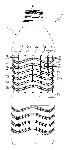
L'invention concerne un récipient en plastique (10) présentant un rapport optimal de la résistance annulaire à la résistance au remplissage par le haut, qui comprend une section de goulot (12) et une section de corps principal, de manière générale cylindrique (14). La section de corps principal comprend une paroi latérale (16) présentant une première pluralité de nervures (18, 20, 21, 24), de manière générale verticales, définies en cela. En outre, une seconde pluralité de nervures (26, 28, 30, 32, 34, 36) sous forme d'ondulations, de manière générale horizontales, sont définies dans la paroi latérale. Les nervures sous forme d'ondulations, de manière générale horizontales, croisent les nervures, de manière générale verticales, conférant ainsi au récipient (10), de meilleures caractéristiques de résistance.


Abrégé anglais


A plastic container (10) that exhibits an optimal ratio of hoop strength to
top load strength includes a finish portion (12) and generally cylindrical
main body portion (14). The main body portion includes a sidewall (16) that
has a first plurality of generally vertical ribs (18, 20, 21, 24) defined
therein. In addition, a second plurality of generally horizontal wave (26, 28,
30, 32, 34, 36) shaped ribs is defined in the sidewall. The generally
horizontal wave shaped ribs intersect with the generally vertical ribs,
thereby imparting enhanced strength characteristics to the container (10).

Revendications

Note : Les revendications sont présentées dans la langue officielle dans laquelle elles ont été soumises.


CLAIMS
1. A plastic container, comprising:
a finish portion; and
a generally cylindrical main body portion, said main body portion comprising a
sidewall having a plurality of generally vertical ribs defined therein
parallel to the
revolution axis of the cylindrical main body portion, the vertical ribs being
concave, said
sidewall further having a plurality of generally horizontal wave shaped ribs
defined
therein, at least one of said generally horizontal wave shaped ribs having an
amplitude
that is within a range of about 4.5 percent to about 30 percent of its
wavelength, and at
least one of said generally vertical ribs intersecting with more than one of
said generally
horizontal wave shaped ribs.
2. A plastic container according to claim 1, wherein said container is
fabricated from
a plastic material comprising polyethylene terephthalate.
3. A plastic container according to claim 1, wherein said plurality of
generally
vertical ribs comprises at least one rib that is inwardly oriented.
4. A plastic container according to claim 1, wherein said plurality of
generally
horizontal wave shaped ribs comprises at least one rib that is inwardly
oriented.
5. A plastic container according to claim 1, wherein said plurality of
generally
horizontal wave shaped ribs comprises a plurality of wave shaped ribs that
extend
generally parallel to each other.
6. A plastic container according to claim 1, wherein said generally
horizontal, wave
shaped ribs are shaped so as to have a common amplitude and a common
wavelength.
6

7. A plastic container according to claim 6, wherein said sidewall has an
outer
circumference, and said wavelength of said generally horizontal wave shaped
ribs is
within a range of about 6 percent to about 40 percent of said outer
circumference.
8. A plastic container according to claim 1, wherein said at least one
generally
vertical rib intersects said generally horizontal wave shaped ribs at a
location of
maximum amplitude of each intersected horizontal wave shaped rib.
9. A plastic container according to claim 1, wherein said at least one
generally
vertical rib intersects said generally horizontal wave shaped ribs at a
location of
minimum amplitude of each intersected horizontal wave shaped rib.
10. A plastic container according to claim 1, wherein more than one of said
generally
vertical ribs intersect more than one of said generally horizontal wave shaped
ribs, and
each intersected horizontal wave shaped rib is intersected within each
wavelength.
7

Description

Note : Les descriptions sont présentées dans la langue officielle dans laquelle elles ont été soumises.


CA 02556691 2006-08-16
WO 2004/080828 PCT/US2003/035337
s CONTAINER EXHIBITING IMPROVED TOP LOAD PERFORMANCE
BACKGROUND OF THE INVENTION
1. Field of the Invention
This invention relates generally to the field of consumer packaging. More
specifically, this invention relates to plastic containers of the type that
are used to package
consumer beverages, and the strength characteristics of such plastic
containers.
2. Description of the Related Technology
Plastic containers are in wide use commercially throughout the world for
packaging
liquids of all types, including consumer beverages. The most common type of
plastic
1 s container that is used for packaging, for example, soft drinks, is
fabricated from polyethylene
terephthalate (PET) and is molded into a desired shape using a blowmolding
process that is
well known in the industry.
In the design of such containers, a number of factors are ordinarily
considered. The
container must be chemically resistant and should be shaped to avoid
concentration of stress
that result in unwanted failure. In addition, the container must be strong
enough to endure the
packaging process and subsequent handling during the gross packaging, shipping
and retail
display stages.
~ne type of strength that plastic containers are regularly evaluated for it is
that of top
load strength. Top load strength involves resistance to failure, typically
sidewall buckling,
2s when a vertical force is exerted onto the top of the container. Such
vertical force is exerted
onto the container during the filling process and when the closure is
installed onto the
container. In addition, a great deal of vertical force may be exerted onto
filled containers
when cases of the containers are stacked during shipping. Another type of
strength that is

CA 02556691 2006-08-16
WO 2004/080828 PCT/US2003/035337
regularly evaluated in the design of plastic containers is hoop strength. Hoop
strength is the
resistance provided by the container against the tendency of the container
sidewall to bow
outwardly or deflect inwardly when the contents of the container are under
pressurization or
when external forces are applied to the outside of the container, which of
course is a common
scenario in the packaging and transportation of carbonated soft drinks.
It is generally known in the industry that circumferential reinforcement such
as
ribbing tends to increase hoop strength, and that vertical reinforcement has a
favorable efFect
on top load strength. However, it should be understood that there is a to
economic
disincentive to provide any more reinforcement to a plastic container design
than is
absolutely necessary, because increased reinforcement tends to make the
container heavier
and thus more expensive to manufacture. A need exists, then, for a plastic
container design
that optimizes hoop strength and top load strength while minimizing the amount
of plastic
material that is necessary to fabricate the container.
SUMMARY ~F TIIE INVENTI~N
Accordingly, it is an object of the invention to provide a plastic container
design that
optimizes hoop strength and top load strength wlule minmizing the amount of
plastic
material that is necessary to fabricate the container.
In order to achieve the above and other objects of the invention, a plastic
container
that is constructed according to a first aspect of the invention includes a
finish portion9 and a
generally cylindrical main body portion, said main body portion comprising a
sidewall having
a first plurality of generally vertical ribs defined therein, the sidewall
further having a second
plurality of generally horizontal wave shaped ribs defined therein, at least
one of the generally
horizontal wave shaped ribs intersecting with at least one of the generally
vertical ribs,
whereby enhanced strength characteristics are imparted to the container.
These and various other advantages and features of novelty that characterize
the
invention are pointed out with particularity in the claims annexed hereto and
forming a part
' hereof. However, for a better understanding of the invention, its
advantages, and the objects
2

CA 02556691 2006-08-16
WO 2004/080828 PCT/US2003/035337
obtained by its use, reference should be made to the drawings which form a
further part
hereof, and to the accompanying descriptive matter,,in which there is
illustrated and described
a preferred embodiment of the invention.
BRIEF DESCRIPTION OF THE DRAWINGS
FIGURE 1 is a side elevational view of a plastic container that is constructed
according to a preferred embodiment of the invention;
FIGURE 2 is a cross-sectional view taken along lines 2-2 in FIGURE l;
FIGURE 3 is a cross-sectional view taken along blinds 3-3 in FIGURE l; and
FIGURE 4 is a diagrammatical depiction of one of the wave-shaped ribs with the
circumference of the container represented along the x-axis.
DETAILED DESC PTION OF THE PREFE D EI~IBODII~IENT(S)
Referring now to the drawings, wherein like reference numerals designate
corresponding structure throughout the views, and referring in particular to
FIGURE l, a
plastic container 10 that is constructed according to a preferred embodiment
of the invention
in eludes a fin1S11 portion 12 and a generally cylindrical main body portion
14~ having an outer
sidewall 16. Preferably, plastic container 10 is fabricated from a plastic
material such as
. polyethylene terephthalate. As may be seen in FIGURE 1, body portion 14 has
a first
plurality of generally vertical ribs 18, 20, 22, 24 defined therein. Vertical
ribs 18, 20, 22, 24,
as shown in the cross-sectional view provided in FIGURE 3, are substantially
concave,
having a radius of depth R~, and extend generally radially inwardly toward the
center axis of
the container 10. The vertical ribs are preferably parallel to each other and
evenly spaced
from each other over the outer circumference of the main body portion 14 of
the container 10.
As may further be seen in FIGURE 1, the sidewall 16 further has a second
plurality of
generally horizontal wave shaped ribs 26, 28, 30, 32, 34, 36 defined therein.
The generally
horizontal wave shaped ribs 26, 28, 30, 32, 34, 36 preferably extend so as to
be parallel with
each other and are substantially evenly spaced from each other. It follows,
then, that each of

CA 02556691 2006-08-16
WO 2004/080828 PCT/US2003/035337
the wave shaped ribs has a common amplitude A and wavelength with each of the
other wave
shaped ribs, with the amplitude A being defined as the peak to peak vertical
distance between
the uppermost point of the wave crest to the lowermost point of the adjacent
wave trough and
the wavelength being defined as the circumferential peak to peak distance
traveled by the rib
from wave crest to wave crest. Each horizontal wave shaped rib is
substantially concave,
having a radius of depth R,, and extending inwardly toward the center axis of
the container
10. As may be seen in FIGURE l, at least one of the generally horizontal wave
shaped ribs
intersects with at least one of said generally vertical ribs, whereby enhanced
strength
characteristics are imparted to the container.
In the preferred embodiment, it will be seen that each of the generally
horizontal wave
shaped ribs 26, 28, 30, 32, 34, 36 intersects with each of the 16 vertical
ribs. Preferably, a
plurality, and more preferably at least three of the vertical ribs intersect
each wave shaped rib
within each wavelength. According to one important aspect of the invention,
the location or
placement of the vertical ribs is harmonized with respect to the waveform of
at least one of
the horizontal ribs. In the preferred embodiment, the vertical ribs 18, 20,
22, 24 will intersect
each of the generally horizontal wave shaped ribs 26, 28, 30, 32, 34, 36 in a
repeating pattern
such that each of the vertical ribs 18 intersects each wave shaped rib at the
lowermost point of
the wave trough, and so that each of the vertical ribs 20 intersects each wave
shaped rib at a
median location between the wave trough and an adjacent wave peak. Also, each
vertical rib
22 will intersect each wave shaped rib at the wave peak and each vertical rib
24 will intersect
each wave shaped rib at a median location between the wave peak and the next
wave trough.
Accordingly, at least one of the generally vertical ribs 18, 20, 22, 24
intersects at least one of
the generally horizontal wave shaped ribs 26, 28, 30, 32, 34, 36 at a location
of maximum
amplitude of the wave shaped rib, and another one of the generally vertical
ribs intersects the
horizontal wave shaped rib at a location of minimum amplitude. This is
believed to
maximize both the hoop strength and top load strength that is achievable by
the structure.
As may be visualized in FIGURE 1, sidewall 16 of the generally cylindrical
main
body portion 14 has an outer circumference. As is shown in FIGURE 4, which is
a
diagrammatical depiction of one of the wave-shaped ribs with the circumference
of the
4

CA 02556691 2006-08-16
WO 2004/080828 PCT/US2003/035337
container represented along the x-axis, each wave-shaped rib preferably has a
repeating
wavelength ~, and a common amplitude A. An angle A is defined by a triangle,
two legs of
which are equal to the amplitude A and one-half the wavelength ~,. Preferably,
the amplitude
A of the wave shaped ribs is within a range of about 4.5 percent to about 30
percent of the
wavelength ~,, which corresponds to angle 8 being within a range of about 5
degrees to about
30 degrees. The wavelength ~, should preferably be about 6 percent to about 40
percent of the
outer circumference of the container.
It is to be understood, however, that even though numerous characteristics and
advantages of the present invention have been set forth in the foregoing
description, together
with details of the structure and function of the invention, the disclosure is
illustrative only,
and changes may be made in detail, especially in matters of shape, size and
arrangement of
parts within the principles of the invention to the full extent indicated by
the broad general
meaning of the terms in which the appended claims axe expressed.
5

Dessin représentatif
Une figure unique qui représente un dessin illustrant l'invention.
États administratifs

2024-08-01 : Dans le cadre de la transition vers les Brevets de nouvelle génération (BNG), la base de données sur les brevets canadiens (BDBC) contient désormais un Historique d'événement plus détaillé, qui reproduit le Journal des événements de notre nouvelle solution interne.

Veuillez noter que les événements débutant par « Inactive : » se réfèrent à des événements qui ne sont plus utilisés dans notre nouvelle solution interne.

Pour une meilleure compréhension de l'état de la demande ou brevet qui figure sur cette page, la rubrique Mise en garde , et les descriptions de Brevet , Historique d'événement , Taxes périodiques et Historique des paiements devraient être consultées.

Historique d'événement

Description Date
Inactive : Périmé (brevet - nouvelle loi) 2023-11-06
Représentant commun nommé 2019-10-30
Requête pour le changement d'adresse ou de mode de correspondance reçue 2018-06-11
Lettre envoyée 2014-07-22
Inactive : Transferts multiples 2014-06-27
Inactive : Lettre officielle 2014-05-21
Inactive : Transfert individuel 2014-04-24
Accordé par délivrance 2012-08-21
Inactive : Page couverture publiée 2012-08-20
Préoctroi 2012-06-11
Inactive : Taxe finale reçue 2012-06-11
Un avis d'acceptation est envoyé 2011-12-13
Lettre envoyée 2011-12-13
Un avis d'acceptation est envoyé 2011-12-13
Inactive : Approuvée aux fins d'acceptation (AFA) 2011-12-08
Modification reçue - modification volontaire 2011-07-28
Inactive : Dem. de l'examinateur par.30(2) Règles 2011-02-07
Modification reçue - modification volontaire 2010-10-06
Inactive : Dem. de l'examinateur par.30(2) Règles 2010-04-06
Modification reçue - modification volontaire 2009-09-28
Modification reçue - modification volontaire 2009-08-28
Lettre envoyée 2008-12-10
Toutes les exigences pour l'examen - jugée conforme 2008-10-31
Exigences pour une requête d'examen - jugée conforme 2008-10-31
Requête d'examen reçue 2008-10-31
Lettre envoyée 2007-01-30
Inactive : Lettre de courtoisie - Preuve 2007-01-09
Exigences relatives à une correction du demandeur - jugée conforme 2007-01-08
Inactive : Notice - Entrée phase nat. - Pas de RE 2007-01-08
Inactive : Transfert individuel 2007-01-05
Inactive : Lettre de courtoisie - Preuve 2006-10-17
Inactive : Page couverture publiée 2006-10-16
Inactive : Notice - Entrée phase nat. - Pas de RE 2006-10-10
Demande reçue - PCT 2006-09-19
Exigences pour l'entrée dans la phase nationale - jugée conforme 2006-08-16
Demande publiée (accessible au public) 2004-09-23

Historique d'abandonnement

Il n'y a pas d'historique d'abandonnement

Taxes périodiques

Le dernier paiement a été reçu le 2011-11-07

Avis : Si le paiement en totalité n'a pas été reçu au plus tard à la date indiquée, une taxe supplémentaire peut être imposée, soit une des taxes suivantes :

  • taxe de rétablissement ;
  • taxe pour paiement en souffrance ; ou
  • taxe additionnelle pour le renversement d'une péremption réputée.

Les taxes sur les brevets sont ajustées au 1er janvier de chaque année. Les montants ci-dessus sont les montants actuels s'ils sont reçus au plus tard le 31 décembre de l'année en cours.
Veuillez vous référer à la page web des taxes sur les brevets de l'OPIC pour voir tous les montants actuels des taxes.

Titulaires au dossier

Les titulaires actuels et antérieures au dossier sont affichés en ordre alphabétique.

Titulaires actuels au dossier
PLASTIPAK PACKAGING, INC.
Titulaires antérieures au dossier
MICHAEL MOONEY
SATYA KAMINENI
Les propriétaires antérieurs qui ne figurent pas dans la liste des « Propriétaires au dossier » apparaîtront dans d'autres documents au dossier.
Documents

Pour visionner les fichiers sélectionnés, entrer le code reCAPTCHA :


Pour visualiser une image, cliquer sur un lien dans la colonne description du document. Pour télécharger l'image (les images), cliquer l'une ou plusieurs cases à cocher dans la première colonne et ensuite cliquer sur le bouton "Télécharger sélection en format PDF (archive Zip)" ou le bouton "Télécharger sélection (en un fichier PDF fusionné)".

Liste des documents de brevet publiés et non publiés sur la BDBC .

Si vous avez des difficultés à accéder au contenu, veuillez communiquer avec le Centre de services à la clientèle au 1-866-997-1936, ou envoyer un courriel au Centre de service à la clientèle de l'OPIC.


Description du
Document 
Date
(aaaa-mm-jj) 
Nombre de pages   Taille de l'image (Ko) 
Abrégé 2006-08-15 2 71
Revendications 2006-08-15 2 80
Description 2006-08-15 5 271
Dessins 2006-08-15 2 41
Dessin représentatif 2006-08-15 1 31
Revendications 2010-10-05 2 59
Revendications 2011-07-27 2 59
Dessin représentatif 2012-07-29 1 13
Avis d'entree dans la phase nationale 2006-10-09 1 192
Avis d'entree dans la phase nationale 2007-01-07 1 205
Courtoisie - Certificat d'enregistrement (document(s) connexe(s)) 2007-01-29 1 127
Rappel - requête d'examen 2008-07-07 1 119
Accusé de réception de la requête d'examen 2008-12-09 1 176
Avis du commissaire - Demande jugée acceptable 2011-12-12 1 163
Courtoisie - Certificat d'enregistrement (document(s) connexe(s)) 2014-07-21 1 104
Taxes 2011-11-06 1 157
PCT 2006-08-15 6 174
Correspondance 2006-10-09 1 27
Taxes 2006-10-29 1 39
Correspondance 2007-01-07 1 27
Taxes 2007-11-04 1 40
Correspondance 2012-06-10 2 50
Correspondance 2014-05-20 1 16