Language selection

Search

Patent 2556854 Summary

Third-party information liability

Some of the information on this Web page has been provided by external sources. The Government of Canada is not responsible for the accuracy, reliability or currency of the information supplied by external sources. Users wishing to rely upon this information should consult directly with the source of the information. Content provided by external sources is not subject to official languages, privacy and accessibility requirements.

Claims and Abstract availability

Any discrepancies in the text and image of the Claims and Abstract are due to differing posting times. Text of the Claims and Abstract are posted:

  • At the time the application is open to public inspection;
  • At the time of issue of the patent (grant).
(12) Patent: (11) CA 2556854
(54) English Title: SAFETY SEAT
(54) French Title: SIEGE DE SECURITE
Status: Granted
Bibliographic Data
(51) International Patent Classification (IPC):
  • B60N 2/885 (2018.01)
  • B60N 2/888 (2018.01)
(72) Inventors :
  • CARINE, DAVID SHAUN (United Kingdom)
(73) Owners :
  • BRITAX EXCELSIOR LIMITED (United Kingdom)
(71) Applicants :
  • BRITAX EXCELSIOR LIMITED (United Kingdom)
(74) Agent: BERESKIN & PARR LLP/S.E.N.C.R.L.,S.R.L.
(74) Associate agent:
(45) Issued: 2013-06-11
(86) PCT Filing Date: 2005-03-11
(87) Open to Public Inspection: 2005-09-22
Examination requested: 2010-02-16
Availability of licence: N/A
(25) Language of filing: English

Patent Cooperation Treaty (PCT): Yes
(86) PCT Filing Number: PCT/GB2005/000966
(87) International Publication Number: WO2005/087537
(85) National Entry: 2006-08-17

(30) Application Priority Data:
Application No. Country/Territory Date
0405716.2 United Kingdom 2004-03-13
0405717.0 United Kingdom 2004-03-13

Abstracts

English Abstract


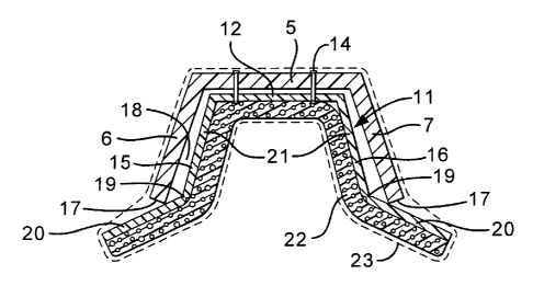
A deformable, polypropylene-moulding lining (11), is provided in a head rest.
It has a crosspiece (12), clipped (14) to the head support (5) and right and
left deformable wings (15, 16). These are longer than the support wings (5, 6)
of the head part (4), extending past distal edges (17) of the support wings.
The deformable wings are spaced inwards from the support wings, with voids
(18) defined between them. The deformable wings are divided into two in their
forwards extent by a living hinge (19) into a front portion (20) and a rear
portion (21). The living hinge is positioned just inside the distal edges of
the shell wings. The injection moulded lining has its own foam materiel lining
(22), the whole being covered with upholstery (23). The result of the
arrangement is that if an occupant's head H impacts the lining in side impact
of the vehicle equipped with the seat, the relevant lining wing will be
pressed against the shell wing. This involves energy absorbing (maximum
acceleration limiting) deformation of not only the foam material, but also of
the lining wing and to a less extent of the shell wing. With the lining wing
deformation (24), the front portion (20) of the lining wing pivots forwards
about the shell edge (17), from a position swept back with respect to the
shell wing to a position generally in line with the compressed inner portion
of the lining.


French Abstract

L'invention concerne un revêtement intérieur (11) de moulage en polypropylène, déformable, comprenant un appui-tête. Ledit revêtement comprend une traverse (12) fixée (14) à un support de tête (5) et des ailes (15, 16) gauche et droite déformables, celles-ci étant plus longues que les ailes supports (5, 6) de la partie tête (4), s'étendant après les bords distaux (17) des ailes supports. Les ailes déformables sont espacées à l'intérieur des ailes supports, au moyen d'espaces (18) définis entre elles. Les ailes déformables sont divisées en deux dans leur extension avant par une charnière (19), une partie avant (20) et une partie arrière (21). La charnière est positionnée à l'intérieur des bords distaux des ailes de l'enveloppe. Le revêtement intérieur moulé par injection comprend un revêtement en mousse (22) propre, ce dernier étant recouvert par du rembourrage (23). Il en résulte que lors d'un impact de la tête de l'occupant (H) avec le revêtement, dans le cas d'un choc latéral du véhicule équipé du siège, l'aile à revêtement correspondant peut être comprimée contre l'aile de l'enveloppe. Cela entraîne une déformation absorbant l'énergie (limite d'accélération maximum) de la mousse, mais également de l'aile comprenant le revêtement, ainsi qu'une extension moindre de l'aile de l'enveloppe. Grâce à la déformation de l'aile (24), la partie avant (20) de l'aile de revêtement pivote en avant autour du bord (17) de l'enveloppe, d'une position arrière par rapport à l'aile de l'enveloppe à une position généralement alignée avec la partie interne comprimée du revêtement.

Claims

Note: Claims are shown in the official language in which they were submitted.


7


What is claimed is:

1. A safety seat comprising:
a winged headrest, the head rest having:
a read head support;
forwards-and-sideways extending support wings, fixed to the rear head
support at respective opposite sides thereof; and
deformable extensions of the support wings, each extension being
hingedly connected to its support wing remote from the rear head support and
normally
extending obliquely forwards and laterally outwards of its support wing,
whereby on lateral impact including impact of the winged headrest with a side
part of a vehicle with the extension on the impacted side striking the side
part first, the
extension hinges inwards.

2. A safety seat as claimed in claim 1, wherein the deformable extensions
are
formed integrally with support wings.

3. A safety seat as claimed in claim 2, wherein the rear head support, the
support
wings and the deformable extensions are an integral injection moulding with
living
hinges being provided between the support wings and the extensions.

4. A safety seat comprising:
a winged headrest, the head rest having:
a rear head support, and forwards-and-sideways extending support
wings fixed to the rear head support at respective opposite sides thereof and
defining
distal edges; and
a deformable lining secured to the winged head rest, the deformable lining
comprising:a head support crosspiece; and
deformable wings fixed to the crosspiece, the deformable wings
extending beyond the support wings and divided into front and rear portions by
a hinge
positioned within the distal edges of the support wings, whereby on lateral
impact of the

8


winged headrest with a side part of a vehicle the front portions of the
deformable wings
hinge inwards.

5. A safety seat as claimed in claim 4, wherein the deformable lining further

comprises an at least partially rigid lining.

6. A safety seat as claimed in claim 5, wherein:
the deformable lining is secured to the headrest at a root between the rear
head
support and its support wings; and
the deformable lining abuts the distal end of the support wings and defines
voids
between itself and the support wings, whereby on lateral impact including
impact of the
head of an occupant of the safety seat with one of the deformable wings:
head acceleration energy is absorbed in deformation of the deformable
wing towards its support wing; and
as the deformable wing is deformed towards its support wing, the front
portion extending past the distal edge of its support wing pivots about the
distal edge
and moves inwards with respect to the support wing.

7. A safety seat as claimed in claim 4, wherein the deformable wings are
individually connected to the rear head support.

8. A safety seat as claimed in claim 7, wherein the deformable wings comprise

tongues on the deformable wings engaging in slots in the rear head support.

9. A safety seat as claimed in any one of claims 4 to 8, wherein the
deformable
wings are provided with energy absorbent pads on their inner sides, away from
their
respective support wings.

10. A safety seat as claimed in any one of claims 4 to 9, wherein the
deformable
wings are covered with upholstery fabric.

11. A safety seat comprising:
a winged headrest, the head rest having:

9


a rear head support;
forwards-and-sideways extending support wings, fixed to the rear head
support at respective opposite sides thereof; and
deformable lining wings for the support wings, each lining wing:
being secured to the headrest at a root between the rear head
support and its support wing;
abutting the distal end of its support wing; and
defining a void between itself and its support wing,
whereby on lateral impact including impact of the head of an occupant of the
safety seat with one of the lining wings, head acceleration energy is absorbed
in
deformation of the lining wing towards its support wing.

12. A safety seat as claimed in claim 11, wherein the deformable lining wings
each
have a forwards extension past the distal end of its support wing, whereby on
such
lateral impact, as the lining wing is deformed towards its support wing, it
pivots about
the distal end and the forwards extension is pivotally moved inwards with
respect to the
lateral extent of the wings.

13. A safety seat as claimed in claim 12, wherein the lining wings and their
forwards extension are of uniform cross-section.

14. A safety seat as claimed in claim 12, wherein the lining wings and their
forwards extension are provided with a hinge line therebetween close to but
set in from
the respective distal end, whereby they are weakened to enable the hinge lines
to abut
the support wings on deformation to provide predictable inwards movement of
the
support wings.

15. A safety seat as claimed in claim 14, wherein the weakening is a living
hinge.

16. A safety seat as claimed in any one of claims 11 to 15, wherein the lining
wings
are provided with energy absorbent pads on their sides away from their
respective
support wings.

10


17. A safety seat as claimed in any one of claims 11 to 15, wherein the lining
wings
and their pads where provided, together with their crosspiece where provided,
are
covered with upholstery fabric.

Description

Note: Descriptions are shown in the official language in which they were submitted.


WO 2005/087537 CA 02556854 2006-08-17PCT/GB2005/000966

SAFETY SEAT

The present invention relates to a safety seat, particularly though not
exclusively a child safety seat for a vehicle.
Safety seats are designed:
= to restrain the occupant from being thrown more than a certain distance from

the seat in the event of an accident and
= to limit the deceleration (both its maximum value and its period above a
threshold) experienced by an occupant.

A direction in which less distance is available before impact of an occupant
with a vehicle part than some others is sideways towards a window, door or
door
pillar. To restrain sideways movement of an occupant's head, seats can be
provided
with a head protecting structure in the form of a vertical extension of a back
of the
seat, the extension having forwards extending wings for limiting lateral
movement of
the head. In this specification, this structure is referred to as a "winged
headrest". To
avoid the wings causing the self-same problem that the seat is intended to
avoid,
namely injury from impact with a hard surface, the winged headrest is normally
provided with a padded lining.

Accidents involving sideways movement result from lateral impact, namely
impact in oblique or transverse direction involving the impacted vehicle in
substantial
lateral acceleration.
The object of the present invention is to provide a safety seat with improved
head protection.

According to a first aspect of the invention there is provided a safety seat
comprising:
= a winged headrest, the head rest having:
= a rear head support,

WO 2005/087537 CA 02556854 2006-08-172
PCT/GB2005/000966

= forwards-and-sideways extending support wings, fixed to the rear head
support at respective opposite sides thereof and
= deformable extensions of the support wings, each extension being hingedly

connected to its support wing remote from the rear head support and
normally extending obliquely forwards and laterally outwards of its
support wing,
whereby on lateral impact including impact of the winged headrest with a side
part of
a vehicle with the extension on the impacted side striking the side part
first, the
extension hinges inwards.
Such hinging in provides an enhanced area of protection of the head of an
occupant of the seat from impact with the vehicle part.

Whilst it can be envisaged that the deformable extensions can be formed
integrally with the headrest, as by integral injection moulding and provision
of a
living hinge, in the preferred embodiment, they are provided as pivotal
extensions of a
lining within the winged headrest.

In particular, the lining can be:
= the lining is secured to the headrest at a root between the rear head
support and
its support wings,
= the lining has lining wings within the support wings,
= the lining via its pivotal extensions abuts the distal end of the
support wings,
with hinged connections between the lining wings and the lining pivotal
extensions being within the distal end of the support wings and
= the lining defines voids between itself and the support wings,
whereby on lateral impact including impact of the head of an occupant of the
safety
seat with one of the lining wings:
= head acceleration energy is absorbed in deformation of the lining wing
towards its support wing and
= as the lining wing is deformed towards its support wing, the lining
extension
past the distal end of its support wing pivots about the distal end and the

WO 2005/087537
CA 02556854 2006-08-17 3
PCT/GB2005/000966
.
forwards extension is pivotally moved inwards with respect to the lateral
extent of the wings.

It should be noted that the safety seat of the invention has been defined in a
forwards facing orientation. If the seat is installed to face rearwards, the
head support
will be in front of the wings, which will be rearwards-and-sideways facing.

Despite careful design of winged headrests and their linings, their
effectiveness can be limited by the need to enable the occupant to feel
unencumbered,
encumbrance tending to cause nausea.

An advantage of this invention is that a safety seat fitted with the forwards
extensions provides enhanced protection without the feeling of encumbrance
that
would result from having them fixed in the position to which they are adapted
to
pivot.

Whilst it can be envisaged that the deformable lining wings could be
individually connected to the rear head support, as by tongues on the lining
wings
engaging in slots in the rear head support; in the preferred embodiment, the
two lining
wings are interconnected by a crosspiece abutting the rear head support.

The lining wings can be provided with energy absorbent pads on their sides
away from their support wings, i.e. on their inner sides.

Normally the lining wings and their pads where provided, together with their
crosspiece where provided, will be covered with upholstery fabric.

According to a second aspect of the invention there is provided a safety seat
comprising:= a winged headrest, the head rest having:
= a rear head support and
= forwards-and-sideways extending support wings, fixed to the rear
head
support at respective opposite sides thereof

CA 02556854 2012-08-03
4


= deformable lining wings for the support wings, each lining wing
= being secured to the headrest at a root between the rear head support and
its support wing and
= abutting the distal end of its support wing and
= defining a void between itself and its support wing,
whereby on lateral impact including impact of the head of an occupant of the
safety seat
with one of the lining wings, head acceleration energy is absorbed in
deformation of the
lining wing towards its support wing.

Preferably, the deformable lining wings each have a forwards extension past
the
distal end of its support wing, whereby on such lateral impact, as the lining
wing is
deformed towards its support wing, it pivots about the distal end and the
forwards
extension is pivotally moved inwards with respect to the lateral extent of the
wings.

It is envisaged that the lining wings and their forwards extension can be of
uniform cross-section. However, in the preferred embodiment, the lining wings
and
their forwards extension are provided with a hinge line therebetween close to
but set in
from the respective distal end, whereby they are weakened to enable the hinge
lines to
abut the support wings on deformation to provide predicatable inwards movement
of the
support wings.

According to another aspect there is provided a safety seat comprising:
= a winged headrest, the head rest having:
= a rear head support, and forwards-and-sideways extending
support wings fixed to the rear head support at respective opposite sides
thereof and
defining distal edges; and
= a deformable lining secured to the winged head rest, the deformable
lining comprising:
= a head support crosspiece; and

CA 02556854 2012-08-03
4a


= deformable wings fixed to the crosspiece, the deformable wings
extending beyond the support wings and divided into front and rear portions by
a hinge
positioned within the distal edges of the support wings, whereby on lateral
impact of the
winged headrest with a side part of a vehicle the front portions of the
deformable wings
hinge inwards.

To help understanding of the invention, a specific embodiment thereof will now

be described by way of example and with reference to the accompanying
drawings, in
which:
Figure 1 is a perspective view of a shell of a child safety seat to be
equipped
with a first embodiment of a head rest in accordance with the invention;
Figure 2 is a cross-sectional view on the line 1I-II in Figure 1 including the

lining and upholstery of the head rest of Figure 1;
Figure 3 is a simplified view similar to Figure 2 of an occupant's head
impacting the left-hand wing of the seat of Figure 1;
Figure 4 is a similar view of another impact mode;
Figure 5 is a simplified view similar to Figure 3 of a second embodiment of a
head rest in accordance with the invention; and

WO 2005/087537 CA 02556854 2006-08-175
PCT/GB2005/000966
Figure 6 is a similar view of the sec ond head rest on impact.

Referring first to Figure 1 of the drawings, a child safety seat has a chassis
or
shell 1 comprising a squab 2 and a back 3. The shell can be a unitary moulding
or a
two part moulding of the squab and the back. Above the back, the shell has a
head
part 4 having a rear head support 5 and a pair of right and left forwards-and-
sideways
extending support wings 6,7. The shell is a polypropylene moulding with the
head
rest being moulded integrally with the rest of the moulding.

In accordance with the invention and as shown in Figure 2, a deformable
lining 11, also a polypropylene moulding, is provided in the head rest. It has
a
crosspiece 12, clipped 14 to the head support 5 and right and left deformable
wings
15,16. These are longer than the support wings 5,6 of the head part 4,
extending past
distal edges 17 of the support wings. It should be noted also that the
deformable
wings are spaced inwards from the support wings, with voids 18 defined between

them. The deformable wings are divided into two in their forwards extent by a
living
hinge 19 into a front portion 20 and a rear portion 21. The living hinge is
positioned
just inside the distal edges of the shell wings.

The injection moulded lining has its own foam material lining 22, the whole
being covered with upholstery 23.

The result of the arrangement is that if, as shown in Figure 3, an occupant's
head H impacts the lining in side impact of the vehicle equipped with the
seat, the
relevant lining wing will be pressed against the shell wing. This involves
energy
absorbing (maximum acceleration limiting) deformation of not only the foam
material, but also of the lining wing and to a less extent of the shell wing.
These
deformations lead to the result that the acceleration of the head is limited
from what it
would have been in the absence of the lining wings. The lining wing
deformation 24
is shown in Figure 3 and with it compressing against the shell wing, the front
portion
20 of the lining wing pivots forwards about the shell edge 17, from a position
swept
back with respect to the shell wing to a position generally in line with the
compressed
inner portion of the lining. This provides for protection of the head in
impact with a
side window for instance even outside the distal edges, by approximately the
length of

WO 2005/087537 CA 02556854 2006-08-176
PCT/GB2005/000966
the front portion beyond the living hinge. Whilst such impact may be thought
unlikely if the head has impacted inside the head rest, we are aware from
tests that
there is a high likelihood of the head moving out of the head rest during a
side impact.

Typically, the lining moulding will be 3mm thick and the foam material 12mm
thick, with a 28gmiltr density in EPS. Both lining will be reduced to half its
thickness
at the hinge. The foam also can be reduced in thickness at the hinge, to
facilitate the
pivoting.
10' Turning now to Figure 4, it shows an impact mode, wherein
the squab of the
seat moves less than the top of the seat, as would be the case where the squab
impact
a wheel arch and causes the top of the seat to pivot against the side window a
car. In
such impact, and under inertia of the occupant reacting against shoulder wings
of the
seat shell, the remote end of the front portion 20 can strike the window W
before the
head strikes the lining. This action causes the front portion to pivot about
its living
hinge 19.

Turning on to Figure 5 & 6, the head rest thereshown can have an EPS and
upholstery lining, neither of which are shown. The headrest as such has a rear
head
support 105 and a pair of right and left forwards-and-sideways extending
support
wings 106,107. Integrally moulded with the wings are extensions 120, connected
to
thereto at living hinges 119. The extensions extend forwards and laterally
outwards.

On impact as in Figure 4, the extensions pivot in to provide an enhanced
region of protection from impact of the head with the vehicle side.

Representative Drawing
A single figure which represents the drawing illustrating the invention.
Administrative Status

For a clearer understanding of the status of the application/patent presented on this page, the site Disclaimer , as well as the definitions for Patent , Administrative Status , Maintenance Fee  and Payment History  should be consulted.

Administrative Status

Title Date
Forecasted Issue Date 2013-06-11
(86) PCT Filing Date 2005-03-11
(87) PCT Publication Date 2005-09-22
(85) National Entry 2006-08-17
Examination Requested 2010-02-16
(45) Issued 2013-06-11

Abandonment History

There is no abandonment history.

Payment History

Fee Type Anniversary Year Due Date Amount Paid Paid Date
Registration of a document - section 124 $100.00 2006-08-17
Application Fee $400.00 2006-08-17
Maintenance Fee - Application - New Act 2 2007-03-12 $100.00 2006-08-17
Maintenance Fee - Application - New Act 3 2008-03-11 $100.00 2008-02-22
Maintenance Fee - Application - New Act 4 2009-03-11 $100.00 2009-02-11
Maintenance Fee - Application - New Act 5 2010-03-11 $200.00 2009-12-04
Request for Examination $800.00 2010-02-16
Maintenance Fee - Application - New Act 6 2011-03-11 $200.00 2010-12-24
Maintenance Fee - Application - New Act 7 2012-03-12 $200.00 2012-01-09
Maintenance Fee - Application - New Act 8 2013-03-11 $200.00 2013-03-11
Final Fee $300.00 2013-03-22
Maintenance Fee - Patent - New Act 9 2014-03-11 $200.00 2014-03-03
Maintenance Fee - Patent - New Act 10 2015-03-11 $250.00 2015-02-27
Maintenance Fee - Patent - New Act 11 2016-03-11 $250.00 2016-02-29
Maintenance Fee - Patent - New Act 12 2017-03-13 $250.00 2017-02-27
Maintenance Fee - Patent - New Act 13 2018-03-12 $250.00 2018-02-15
Maintenance Fee - Patent - New Act 14 2019-03-11 $250.00 2019-02-14
Maintenance Fee - Patent - New Act 15 2020-03-11 $450.00 2020-02-19
Maintenance Fee - Patent - New Act 16 2021-03-11 $459.00 2021-02-24
Maintenance Fee - Patent - New Act 17 2022-03-11 $458.08 2022-02-24
Maintenance Fee - Patent - New Act 18 2023-03-13 $473.65 2023-02-28
Maintenance Fee - Patent - New Act 19 2024-03-11 $624.00 2024-03-08
Owners on Record

Note: Records showing the ownership history in alphabetical order.

Current Owners on Record
BRITAX EXCELSIOR LIMITED
Past Owners on Record
CARINE, DAVID SHAUN
Past Owners that do not appear in the "Owners on Record" listing will appear in other documentation within the application.
Documents

To view selected files, please enter reCAPTCHA code :


To view images, click a link in the Document Description column. To download the documents, select one or more checkboxes in the first column and then click the "Download Selected in PDF format (Zip Archive)" or the "Download Selected as Single PDF" button.

List of published and non-published patent-specific documents on the CPD .

If you have any difficulty accessing content, you can call the Client Service Centre at 1-866-997-1936 or send them an e-mail at CIPO Client Service Centre.


Document
Description 
Date
(yyyy-mm-dd) 
Number of pages   Size of Image (KB) 
Drawings 2006-08-17 3 43
Claims 2006-08-17 3 114
Abstract 2006-08-17 2 77
Description 2006-08-17 6 249
Representative Drawing 2006-10-16 1 13
Cover Page 2006-10-17 1 55
Description 2012-08-03 7 273
Claims 2012-08-03 4 121
Cover Page 2013-05-21 1 56
Fees 2009-12-04 1 61
Correspondence 2009-04-22 1 24
PCT 2006-08-17 18 667
Assignment 2006-08-17 3 104
Correspondence 2006-10-12 1 26
Correspondence 2007-05-07 1 22
Assignment 2007-08-16 3 85
Fees 2008-02-22 1 57
Fees 2009-02-11 1 56
Assignment 2006-08-17 5 150
Prosecution-Amendment 2010-02-16 1 62
Fees 2010-12-24 1 67
Fees 2012-01-09 1 64
Prosecution-Amendment 2012-02-03 2 39
Prosecution-Amendment 2012-08-03 8 231
Fees 2013-03-11 1 163
Correspondence 2013-03-22 2 52
Change of Agent 2015-11-24 3 88
Office Letter 2015-11-30 1 19
Office Letter 2015-11-30 1 23
Office Letter 2016-03-14 1 27
Maintenance Fee Correspondence 2016-04-27 1 36
Maintenance Fee Correspondence 2016-04-27 2 73
Office Letter 2016-07-22 1 21