Note: Descriptions are shown in the official language in which they were submitted.
CA 02557228 1999-O1-25
1
SEED TUBE FOR SEED METERING APPARATUS
FIELD OF THE INVENTION
The present invention generally relates to agricultural implements having
mechanisms
for metering seed delivery at a controlled rate to the ground over which the
implement is
drawn and, more particularly, to a seed tube for directing seeds from the seed
delivery
mechanism for gravitational deposit on the ground.
BACKGROUND OF THE INVENTION
Agricultural implements such as planters and grain drills typically include
mechanisms
wh'ch meter or dispense individual seeds to the ground. As the implement is
drawn across a
field seeds are preferably deposited into furrows in the ground. As will be
appreciated by
those skilled in the art, the seeds which are planted vary both in size,
weight and shape
depending upon the particular planting.
Various types of seed metering mechanisms are known in the art. Some seed
metering mechanisms are a mechanical type wherein individual seeds are picked
from a seed
mass and discharged to the ground for deposit within the furrows by mechanical
devices.
Other seed metering mechanisms utilize an apertured rotating disk that
operates under the
influence of air pressure differentials. Other metering mechanisms rely on a
rotating drum
1
CA 02557228 1999-O1-25
2,
that picks up seed from a seed mass and delivers the seeds through elongated
air conduits for
deposit within the furrows.
Regardless of the type of seed metering mechanism used, it is desirable to
deposit a
given quantity of seeds within a furrow over a predetermined distance. Also,
it is important
that the seeds be delivered to the ground in such a way that adjacent seeds
within a furrow
are generally equidistantly spaced relative to each other along the length of
the furrow. To
properly deposit the seeds within the furrow requires not only that the seeds
be periodically
dispensed from the metering apparatus in generally uniform relation relative
to each other,
but also that the seeds are directed toward and deposited into the furrow with
minimal
disturbance being imparted to the seeds as they pass from the seed metering
mechanism to
the ground.
In one form, the seed metering mechanism is typically arranged in combination
with a
seed hopper that is carried by the agricultural implement and moves along
therewith at some
nominal speed. It is known to mount a series of seed hoppers in side-by-side
relation with
each other with each seed hopper having its own seed metering mechanism for
controlling
the discharge of seeds to the ground as the implement is pulled there across.
Proper deposit of the seed into the furrow promotes planting, growing, and
subsequent harvesting procedures. If the individual seeds are released from a
housing of the
seed~meter for essentially vertical straight down movement into the furrow
below under the
effects of gravity, the ability to positively control the seed deposit is
lost. Because the seed
meter mechanism is not positioned immediately adjacent to the ground surface,
the seeds
discharged would normally establish~a vertical velocity before they strike the
ground.
Moreover, and because of the movement of the seed metering mechanism with the
implement, the individual seeds exhausted from the housing of the seed
metering mechanism
likewise have a horizontal component of movement. The furrow openings wherein
the seeds
are to be deposited are created in soil and cannot be exact. Thus, the
vertical and horizontal
velocity components of the seeds discharged from the seed metering mechanism
frequently
cause the seeds to bounce upon engagement with the soil and away from the
intended
landing area, resulting in inaccurate and non-uniform distribution of the
seeds within the
furrow.
2
CA 02557228 1999-O1-25
3
To better control the individual seeds as they are discharged from the housing
of the
seed metering mechanism, it is known to use a seed tube depending from a seed
discharge
area of the metering mechanism and extending toward the ground. These known
seed tubes
have an upper portion with a relatively straight configuration in the seed
discharge area of
the seed metering mechanism to provide a relatively smooth reception of the
seeds into the
tube. Such tubes are also known to include a curvature along a lower portion
of the tube.
The curved configuration at the lower portion of the tube serves a dual
purpose. First, the
configuration of the tube is curved a sufficient amount relative to the upper
portion of the
tube to control the vertical velocity component of the seed as it
gravitationally moves toward
a discharge end of the tube. Second, the curved configuration of the lower
portion of the
seed tube is such that it minimizes or eliminates the horizontal velocity
component of the
seeds as they are discharged to the ground. It is known to configure the lower
portion of the
tube with a vertically curved configuration in a direction opposite to the
normal direction of
the impleZnent across a field. The seeds are thereby caused to exit from the
seed tube with
the horizontal velocity component of seeds being generally equal to and
opposite the
horizontal velocity of the implement over the ground.
While such configured or curved tubes have proven effective in controlling the
vertical velocity component of the seeds as they move through the tube while
minimizing or
eliminating the horizontal velocity component of the seeds moving through the
tubes, such
_ seed tubes have been known to introduce problems of their own which detract
from the
advantages obtained through their use in combination with seed metering
mechanisms. A
significant problem involving such seed tube relates to the inherent tendency
for the seeds to
rattle or bounce as they move through the tube. The vibrations inherent with
the seed tube
as it moves across the field exacerbates the seed deflection and delivery
problems. In
addition, seed monitoring devices provided in the seed tube may also increase
the seed
bounce and deflection, if they are mounted to interrupt the flow of seed in
the tube.
Moreover, and because the seeds exhausted from the housing of the seed
metering
mechanism are of different sizes and shapes, each seed will have a different
surface friction
contact which~tends to slow, delay and alter seed travel as it moves between
upper and
lower ends of the seed tube. As a result of such bouncing and frictional
engagement with
3
CA 02557228 1999-O1-25
4~
the tubes, the seeds tend to exit the seed tube at different times and in
unpredictable
manners. As will be appreciated, the inability to maintain substantially equal
distance
spacing between the seeds as they travel through the tube while likewise
losing the ability to
maintain substantially constant or uniform discharge of the seeds from the
tube, results in
non-uniform seed spacings within the furrow.
Thus, there is a need and a desire for a seed tube which is adapted to receive
seeds
from a seed metering mechanism and which is capable of controlling
gravitational movement
of the seeds by minimizing surface friction and seed bouncing as the seeds
move along a
predetermined pathway thereby enhancing controlled delivery of the seeds to
the ground.
There is also a desire to provide a monitoring device to count seeds in the
seed tube which is
arranged to not interfere with the flow of seeds in the seed tube.
SUMMARY OF THE INVENTION
In view of the above, and in accordance with the present invention, there is
provided
a seed tube including a hollow member defining an enclosed and vertically
curved seed
pathway extending lengthwise between upper and lower ends of the hollow
member. In one
embodiment, the hollow member has a front wall, a rear wall and a pair of side
walls. The
front wall of the hollow member is generally separated into an upper portion
and a lower
portion. An opening to receive a monitoring device for monitoring seeds
passing through
the hollow member is positioned near the juncture of the upper and lower front
wall
~ portions.
Preferably, the seed tube has' a fi.tnnel-like configuration between the upper
and lower
ends thereof. That is, the seed tube has a larger cross section toward the
upper end of the
member than toward the lower end so as to promote uninhibited reception of
seeds within
the tube. In addition, the seed tube is curved in a direction opposite the
direction of
movement of the seed metering device. The curved configuration of the seed
tube is such
that the vertical and horizontal components of the seeds moving through the
seed tube are
controlled such that the seeds will eventually simply slide along the lower
front wall portion
of the seed tube as it approaches the lower end where the seeds are
discharged.
4
CA 02557228 1999-O1-25
J
In one embodiment, the upper end of the lower front wall portion of the seed
tube is
positioned in a forward location relative to, or is stepped forward from, the
lower, adjacent
end of the upper front wall portion. In this manner, seeds passing through the
seed tube
slide along the upper front wall portion and fall past the monitoring
apparatus to then slide
along the stepped forward lower front wall portion and then exit the seed
tube. Preferably,
in this embodiment, both the upper front wall portion and the lower front wall
portion have a
constant thickness. The thickness of both the upper and lower front wall
portions is
preferably about 2 mm.
In the stepped forward tube embodiment, the upper and lower front wall
portions are
in the shape of arcs, i.e., they are sections of a circumference of a circle.
The arcs of the
upper and lower front wall portions have different and constant radii. The
radius of the
lower front wall portion is a selected amount greater than the radius of the
upper front wall
portion. Preferably, when the center of these arcs is located at the same
point, the radius of
the upper front wall is about 731 mm and the radius of the lower front wall
portion is about
73 6 mm.
In one embodiment, the front wall of the hollow member further includes a
narrowed
front edge extending upwardly from the lower end of the seed tube. In one
embodiment, the
narrowed front edge extends upwardly from the lower end along the majority
length of the
front wall. In another embodiment, the narrowed front edge extends upwardly
from the
, lower end only along a section of the lower front wall portion. The narrowed
front edge
includes surfaces which angularly diverging in rearward opposite directions
from the forward
edge toward the rear wall. The angularly diverging surfaces extend from the
front edge in
opposite directions and tend to positively direct the seeds moving along the
front wall of the
hollow member toward the narrowed front edge and limit the area in which the
seeds can
move, thereby facilitating their~equidistant spacing relative to each other
and enhancing
delivery of the seeds to the ground.
In a preferred embodiment of the invention, the angularly diverging surfaces
extending in a rearward direction from the front edge form a "V" shaped
configuration
defining an included angle, ranging between about 60° and about
135°, between the
angularly diverging surfaces. As will be appreciated, any angle suitable to
promote positive
5
CA 02557228 1999-O1-25
6.
displacement of the seeds toward the front edge as the seeds gravitationally
move along the
pathway will suffice. Moreover, the angled front edge is configured with a
radius ranging
between about 0.062 inches and about 0.562 inches. The radius curves outwardly
away
from the seed pathway and into planes of the diverging and angularly disposed
surfaces
extending in a rearward direction from the front edge. In addition, in one
embodiment, the
angled front edge extends along the majority of the internal surface of the
front wall. In
another embodiment, the angled front edge extends along only a section of the
interior
surface of the lower front wall portion.
In one embodiment, the majority of the length of the interior surface defining
the
seed pathway has a coefficient of surface friction ranging between about 0.02
and about
0.10. This low surface friction further serves to eliminate increases in
spacing between the
seeds resulting from seed contact regardless of the seed size and shape. In
one form of the
invention, the tube is formed from a molybdenum disulfide filled nylon
material or the like
material having a coefficient of surface friction with the characteristics
described above. In a
preferred form of the invention, the tube is formed from an aliphatic keytone
including, for
example, Carilon~ polymers manufactured by the Shell Chemical Company.
Additives such
as carbon fibers, carbon polymers or stainless steel fibers may be added to
the Carilon~ resin
to make the seed tube resistant to static charge build-up or to make it
electrically conductive.
Carilon~ has been found to provide excellent wear for pressure-velocity and
abrasive
, applications, good dimensional stability, good lubricity and good seed
handling properties.
The curvature of the seed tub8, combined with the low coefficient of surface
friction
and the angularly diverging surfaces extending in a rearward direction from
the front edge of
tube, deadens seed bounce and allows the seeds to be discharged into the
furrow with
substantially equidistant spacing between the seeds. The stepped forward
arrangement for
the lower front wall portion also allows a monitoring device to be used
without disrupting
the flow of seeds in the seed tube.
In one embodiment of the invention, the seed tube is arranged in combination
with a
seed metering apparatus comprising a housing mounted to be moved over ground
in a
predetermined direction and having a hollow interior configuration defining a
hopper area
wherein seeds are held. The seed metering apparatus fi~rther includes a rotary
and apertured
6
CA 02557228 1999-O1-25
7~
disk mounted within the hollow interior of the housing for conveying seeds
from the hopper
to a seed discharge area under the influence of pressure differentials acting
on the disk. The
pressure differentials acting on the disk are blocked in the region of the
seed discharge area
such that seeds are periodically released from the disk within the seed
discharge area of the
housing for deposit to the ground. The upper end of the seed tube is arranged
in seed
receiving relation relative to the seed discharge area of the housing. In one
embodiment, the
upper end of the seed tube is attached to the outside of the seed discharge
area. In an
alternative embodiment, the upper end of the seed tube is attached to the
inside of the seed
discharge area.
These and other aims, objects and advantages of the present invention will be
apparent from the following detailed description, appended claims, and the
following
drawings.
BRIEF DESCRIPTION OF THE DRAWINGS
FIGURE 1 is a schematic side elevational view of a planting unit with a seed
tube in
accordance with the present invention depending from a seed metering
mechanism;
FIGURE 2 is an enlarged schematic side elevational view of a portion of the
seed
metering mechanism illustrated in FIGURE 1 with parts broken away to show a
rotatable
disk~of the seed metering mechanism that plucks individual seeds from a seed
mass and then
discharges the seeds from the seed metering apparatus into a seed tube of the
present
. invention;
FIGURE 3 is an enlarged schematic and side-elevational view of the seed tube
having
a sensor mounted toward the lower end thereof;
FIGURE 4 is a side elevational view of one form of a seed tube according to
the
present invention;
FIGURE S is a front elevational view of the seed tube as schematically
illustrated in
FIGURE 4;
FIGURE 6 is a plan view of the seed tube schematically illustrated in FIGURE
4;
FIGURE 7 is a sectional view of the seed tube taken along line 7-7 of FIGURE
4;
FIGURE 8 is a sectional view taken along line 8-8 ofFIGURE 4;
7
CA 02557228 1999-O1-25
FIGURE 9 is a sectional view taken along line 9-9 of FIGURE 4;
FIGURE 10 is a rear view of the discharge area of the seed tube shown in
FIGURE
4;
FIGURE 11 is an enlarged schematic sectional view of a lower area of the seed
tube
with a sensor arranged in operable association with the seed tube for
detecting the passage
of seeds through the seed tube;
FIGURE 12 is an enlarged sectional view taken along line 12-12 of FIGURE 3;
FIGURE 13 is a view similar to FIGURE 3 showing an alternative seed tube
embodiment according to the present invention particularly suited for smaller
size seeds and
having a sensor secured to the lower end thereof;
FIGURE 14 is a side elevational view of the seed tube schematically
illustrated in
FIGURE 13;
FIGURE 15 is a front elevational view of the seed tube schematically
illustrated in
FIGURE t4;
FIGURE 16 is a sectional view taken along line 16-16 of FIGURE 14;
FIGURE 17 is a sectional view taken along line 17-17 of FIGURE 14;
FIGURE 18 is a sectional view taken along line 18-18 of FIGURE 14;
FIGURE 19 is a rear elevational view of the discharge end of the alternative
embodiment of seed tube schematically illustrated in FIGURE 14;
FIGURE 20 is sectional view of another alternative embodiment of a seed tube
according to the present invention;
FIGURE 21 is an enlarged schematic side elevational view of a portion of the
seed
metering mechanism illustrated in FIGURE 1 with parts broken away to show a
rotatable
disk of the seed metering mechanism that plucks individual seeds from a seed
mass and then
discharges the seeds from the seed metering apparatus into a seed tube of the
present
invention where the seed tube is attached to the inside of the housing of the
seed metering
mechanism;
FIGURE 22 is an enlarged perspective view of an alternative embodiment of a
seed
tube according to the present invention;
8
CA 02557228 1999-O1-25
9.
FIGURE 23 is a side view of the seed tube shown in FIGURE 22;
FIGURE 24 is a rear view of the seed tube shown in FIGURE 22;
FIGURE 25 is a plan view of the seed tube shown in FIGURE 22;
FIGURE 26 is an additional side view of the seed tube shown in FIGURE 22;
FIGURE 27 is a sectional view taken along line A-A of FIGURE 26;
FIGURE 28 is a sectional view taken along line B-B of FIGURE 26;
FIGURE 29 is a sectional view taken along line C-C of FIGURE 26;
FIGURE 30 is a sectional view taken along line D-D of FIGURE 26;
FIGURE 31 is a sectional view taken along line E-E of FIGURE 26;
FIGURE 32 is a sectional view taken along line F-F of FIGURE 26;
FIGURE 33 is a sectional view taken along line G-G of FIGURE 26;
FIGURE 34 is an enlarged side-sectional view of the monitoring apparatus and
upper
and lower front wall portions of the seed tube shown in FIGURE 22; and
FIGURE 35 is an enlarged perspective view of the narrowed front edge of a
section
of the lower front wall portion of the seed tube shown in FIGURE 22.
DETAILED DESCRIPTION OF THE INVENTION
While the present invention is susceptible of embodiment in various forms,
there is
shown in the drawings and will hereinafter be described preferred embodiments
of the
invention with the understanding that the present disclosure is to be
considered as setting
~ forth exemplifications of the invention which are not intended to limit the
invention to the
specific embodiments illustrated.
Referring now to the drawings, wherein like reference numerals indicate like
parts
tlu-oughout the several views, an agricultural implement is schematically
illustrated in
FIGURE 1 and is represented in its entirety by reference numeral 10. Implement
10 includes
an elongated tool bar 12 which ~is supported for movement across and over
fields by a
plurality of wheels (not shown and which is adapted to be towed in a given
forward
direction by a power source such as an off highway tractor or the like.
Attached to the tool
bar 12 are a plurality of planting units 14; with only one planting unit being
shown and
described in detail and from which a complete understanding of the present
invention may be
9
CA 02557228 1999-O1-25
determined. As is well known in the art, the planting units 14 are mounted in
side-by-side
relationship relative to each other long the length of the tool bar 12.
In the illustrated form, each planting unit 14 preferably includes a
conventional
furrow opening apparatus generally indicated in FIGURE 1 by reference numeral
18. As is
5 known in the art, the furrow opening unit 18 preferably includes a pair of
laterally spaced
furrow opener disks 21, a furrow forming point 22, and an opener shoe 24. The
planting
unit 14 further includes a pair of furrow closer disks 26 and a press wheel 28
arranged in
fore-and-aft relationship relative to each other.
As also shown in FIGURE 1, a seed hopper 30 is likewise carried on each
planting
10 unit 14. A seed metering mechanism or apparatus 32 is arranged in seed
receiving relation
relative to the hopper 30 and, in the illustrated embodiment, forms part of
the planting unit
14. The purpose of the seed metering apparatus or mechanism 32 is to uniformly
release
seeds for deposit onto the ground.
As the power source or tractor pulls the tool bar 12 over the ground, in the
given
forward direction, the furrow opener apparatus 18 operates to open a furrow in
the ground.
Seeds from the seed hopper 30 flow into the seed metering mechanism 32 from
whence
seeds are deposited to the ground at a controlled rate. The furrow closer 26
trails the
furrow opening apparatus 18 and, as the implement is drawn across the field,
serves to close
the furrow together and over the seeds dispensed by the seed metering
mechanism 32 into
_ the open furrow. The trailing press wheel 28 serves to compact the soil
closed over the
seeds.
In embodiment illustrated in FIGURE 1, a pesticide hopper 34 is mounted toward
a
rear end of each planting unit 14. Hopper 34 preferably contains an
insecticide and is
provided with conventional dispensing means for applying controlled amounts of
insecticide
where desired in connection with the planting of seeds by each planting unit
14
The seed metering mechanism or apparatus 32 is mounted to and movable with the
hopper 30 in a conventional manner. Suffice it to say, and as shown in FIGURE
2, the seed
metering apparatus 32 includes a housing 38 mounted to be moved over the
ground in a
predetermined direction. In the illustrated embodiment, housing 38 includes a
half shell 40
with a separating wall or baffle 42 and a cover 44. Cover 44 is of somewhat
similar
CA 02557228 1999-O1-25
11,
configuration to and is operably coupled in abutting relationship with the
half shell 40 of
housing 38. Housing 38 has a hollow interior that defines a seed reservoir 46
disposed to
one side of separating wall or baffle 42 and wherein a mass of seeds, received
from the seed
hopper 30 are to be held. A rotary and apertured disk 48 is mounted within the
hollow
interior defined by the housing 38.
As is known in the art, disk 48 defines a series of seed holes or openings 50
circumferentially arranged in predetermined relation relative to each other
and proximate to
the periphery of the disk 48. Individual seeds from the seed reservoir 46 are
drawn to and
re(easably held in each hole or opening 50 in the disk 48 by the effect of air
pressure
differential acting on the disk 48. More specifically, in the embodiment of
seed metering
mechanism illustrated, seeds are drawn to and releasably held in the holes or
openings 50
defined by the disk 48 by the effects of an adjustable pressure from a vacuum
source (not
shown) coupled to the hollow interior of the housing 38.
The individual seeds are carried with the rotating disk 48 until they reach a
seed
discharge area 54 defined by housing 38 on the opposite side of the separating
wall or baffle
42 and which is isolated from the reduced pressure within the interior of
housing 38. As the
holes or openings 50 move into the seed discharge area 54, the pressure
differential acting
on the disk 48 is closed off, resulting in equalization of air pressure acting
on the disk 48 so
that the seeds are no longer retained in the holes or openings 50 as a result
of the pressure
_ differential and gravity acting thereon and the seeds are released for
discharge from the seed
metering mechanism 32. Because the~holes or openings 50 on the seed disk 48
are
equidistantly spaced relative to each other, the seeds released from the disk
48 will have
substantially equidistant spacings relative to each other as they pass or fall
from the
discharge area 54 of housing 38. Individual seeds are typically released from
the disk 48
when each hole or opening 50 reaches approximately a "3 o'clock" position on
the split
housing 38.
A "3 o'clock" seed release position is generally preferred in seed metering
mechanisms 32 of the type shown in FIGURES 1 and 2 because it allows the
direction of
seed to exit from the seed metering mechanism 32 to be aligned with the
direction of
11
CA 02557228 1999-O1-25
12
gravitational pull. This provides for relatively uniform seed delivery within
a wide range of
possible rotational speeds of the seed disk 48.
For reasons known to those skilled in the art, and depending upon the
particular
manufacturer and other considerations, the seed discharge area 54 of a
conventional seed
metering mechanism or apparatus 32 is disposed above the ground surface a
distance
ranging between about 12 inches to about 24 inches. The generally vertical
release of
individual seeds from the seed metering apparatus 32 would normally cause the
individual
seeds to gravitationally fall straight down to the ground below with a
velocity, as mentioned
above, that would cause the seeds to bounce upon ground engagement, resulting
in non-
uniform seed distribution. With the implement 10 being towed across the field
in a given
direction, a horizontal velocity component would likewise be imparted to the
individual
seeds discharged from the seed metering apparatus 32. This horizontal velocity
component
is likewise undesirable because of the non-uniformities in seed distribution
that could result.
Consequently, and according to a first embodiment of the present invention
shown in
FIGURE 3, a seed tube 56 is disposed between the seed discharge area 54 of
each seed
metering mechanism or apparatus 32 and extends closely proximate to the ground
surface
wherein seeds are to be deposited. According to this first embodiment of the
present
invention, and as shown in FIGURE 3, the seed tube 56 preferably includes an
elongated
hollow member 58 defining an enclosed seed pathway 60, Member 58 has upper and
lower
, ends 62 and 64, respectively. The upper end 62 of tube 56 defines an ingress
area 66 to the
passageway 60. As will be appreciated, the ingress area 66 is arranged in seed
receiving
relation with the seed metering apparatus 32. The lower end 64 of tube 56
defines an egress
area 68 from whence seeds are deposited to the ground.
The enclosed seed pathway 60 and preferably tube member 58 has a vertically
curved
configuration between the upper and lower ends 62 and 64, respectively, of
member 58 such
that the ingress and egress areas 66 and 68, respectively, of the pathway 60
are disposed in
different planes. The curved configuration of the pathway 60 extends
rearwardly in a
direction opposite the forward given direction of the seed metering apparatus
32.
Preferably, and as shown in FIGURES 1 and 3, the tube 56 further includes an
apertured
mounting lug 70 for mounting the tube 58 to the planting unit 14.
12
CA 02557228 1999-O1-25
13
The seed tube 56 offers several distinct and different features for
controlling the
seeds as they move along the pathway 60. First, at least the interior surface
of the enclosed
passageway 60 has an extremely low coefficient of surface friction in the
range of about 0.02
to about 0.10. In one form of the invention, the tube 56 is formed or molded
from a
molybdenum disulfide nylon filled material or similar material having a
coefficient of surface
friction in the above range, thus promoting gravitational movement of the
seeds as they
move along the pathway regardless of their size and/or shape. In a preferred
embodiment,
the tube 56 is formed or molded from an aliphatic keytone material, such as an
Carilon~
polymer material manufactured by the Shell Chemical Company. Carilon~ has been
found
to provide excellent wear for pressure-velocity and abrasive applications,
good dimensional
stability, good lubricity and good seed handling properties. Second, the
interior surface of
member 58 is specifically configured to minimize seed rattle or bounce therein
so that
control can be maintained over the metering of the seeds as they pass from the
seed metering
apparatus 32 to the ground.
As shown in FIGURES 4 and 5, the ingress opening 66 at the upper end 62 of
member 58 preferably has a larger cross sectional area than does the egress
opening 68 at
the lower end 64 of member 58. Between its ends, and as will be appreciated
from the
schematic illustrations in FIGURES 4 through 9, the cross sectional area of
the enclosed
pathway 60 of the tube 56 smoothly changes as a firnction of the length of the
tube. As
such, and as the seeds move closer to the discharge opening 68 defined by
tubular member
58, there is less area for the seeds to bounce and move as compared to the
upper end of the
seed tube 56.
Toward its upper end 62, and as shown in FIGURES 6 and 7, the enclosed
passageway 60 is defined by a rear interior surface or wall 72, a pair of
opposed side
surfaces or walls 74 and 76 connected to and extending forwardly from the rear
wall 72, and
a front interior surface or wall 78 joined to each side wall 74 and 76. As
will be appreciated
from the schematic illustrations in FIGURES 6 and 7, the interior surfaces 72,
74, 76 and 78
smoothly converge or taper inwardly toward each other as the tube 56 extends
from an
upper end thereof whereby reducing the cross sectional area of the enclosed
passageway 60
13
CA 02557228 1999-O1-25
14
thus limiting the seed bounce and rattle as the seeds gravitationally move
between opposite
ends 62 and 66 thereof.
As shown in FIGURES 4, 7 and 8, the front wall 78 of the passageway 60
smoothly
tapers and converges into a leading front or forward edge 80. Notably, the
forward edge 80
of the interior passageway 60 is narrowed and generally centralized between
the side
surfaces 74, 76 of the seed pathway 60. The narrowed forward edge 80 extends
upwardly
from the lower end 66 and along the majority of the length of the passageway
60.
Moreover, the front or forward edge 80 preferably follows the vertically
curved
configuration between the upper and lower ends 62 and 64 of member 58.
Turning to FIGURES 8, 9 and 10, along that portion of the pathway 60 including
front edge 80, the interior of the pathway further includes slanted surfaces
82 and 84. The
surfaces 82, 84 angularly diverge rearwardly in opposite directions relative
to each other
from the forward edge 80 and toward the rear wall or surface 72 of the
interior of pathway
60 to form a "V" shaped configuration extending along a major lengthwise
portion of the
front edge 80. The surfaces 82 and 84 define an included angle therebetween
and, in the
illustrated embodiment, are integrally joined to and formed with the side
surfaces 74 and 76.
The included angle defined between the interior surfaces 82 and 84 of the
passageway ?6
ranges between about 60° and about 100°. In a most preferred
form of the invention, the
included angle defined between the surfaces 82 and 84 of the interior pathway
76 is about
90°.
The front or forward edge 80 of pathway 60, along with the surfaces 82 and 84
diverging rearwardly and angularly from edge 80, generally follow and parallel
the vertically
curved configuration of the tube 56 between the upper and lower ends 62 and
64,
respectively. As such, and as shown in FIGURE 4, the curved forward edge 80
and the
surfaces 82, 84 (FIGURE 8) extending rearwardly therefrom, curve in a
direction opposite
the given forward direction of the seed metering apparatus 32 and extend
beneath and
across, in a fore-and-aft direction, the width of the upper end 66 of
passageway 60.
Accordingly, as the individual seeds are released from the metering apparatus
and
gravitationally move through the passageway 60, they inescapingly engage and
are
controlled by the edge 80 and surfaces 82, 84 of the interior passageway 60.
As will be
14
CA 02557228 1999-O1-25
appreciated, as the seeds gravitationally fall and engage surface 82 they will
be positively
directed by the slanted configuration thereof toward the narrowed and centered
forward
edge 80 of the pathway 60. Alternatively, as the individual seeds fall and
engage surface 84
they likewise will be positively directed by the slanted configuration of
surface 84 toward the
5 narrowed and centered forward edge of the pathway 60.
Individual seed size varies depending upon the particular crop being planted.
In one
embodiment, as shown in FIGURES 8 though 10, the front interior edge 80 of the
pathway
60 has a radial configuration extending preferably along the entirety but at
least along the
majority of the length of the forward edge 80. The radius of the forward
interior edge 80
10 ranges between about 0.062 inches and about 0.562 inches. Moreover, the
radial
configuration of the interior edge 80 curves outwardly away from the pathway
60 and into
planes of the diverging and angularly disposed surfaces 82 and 84 e~ctending
rearwardly from
the front edge 80. The radial configuration of the forward edge 80 inhibits
smaller seeds
from becoming entrapped between the oppositely slanted surfaces 82 and 84.
15 Returning to FIGURE 3, in one desired form of the invention, the seed tube
56 has a
conventional sensor or monitoring apparatus 86 arranged in operable
combination therewith.
As is shown, the monitoring apparatus 86 is operably arranged in any suitable
manner
toward the lower end 66 of the tube 56 to provide a more accurate monitoring
of the
individual seeds passing through the passageway 60. In the illustrated
embodiment, the
sensor 86 is mounted on the front and rear sides of seed tube S6. In a most
preferred from
of the invention, the monitoring apparatus 86 is operably arranged relative to
the tube 56
such that it is approximately 6 inches or less from the ground.
As shown in FIGURE 11, the monitoring apparatus 86 is preferably comprised of
a
conventional photodetector including an electric light source 88 and an
electric sensor or eye
90. As well known in the art, the photodetector is capable of producing output
signals
indicative of individual seeds passing between the light source 88 and the
sensor or eye 90.
The output signals are converted to a readout that is preferably provided to
the operator in a
cab region of the tractor (not shown) used to tow the implement 10 (FIGURE 1)
across the
field.
CA 02557228 1999-O1-25
1E
As will be discussed in further detail below, the configuration of the
interior surfaces
defining the enclosed passage 60 of tube 56 are such that individual seeds
have a tendency
and likelihood to slide along the narrowed front edge 80 between the slanted
oppositely
directed surfaces 82, 84 extending rearwardly from the front edge 80.
Accordingly, it is
most beneficial to position the monitoring apparatus where it has the greatest
likelihood of
detecting individual seed passing along the passage 60. In this regard, and
turning now to
FIGURE 12, in one form, the sensor or eye 90 is arranged in operable
combination with the
front edge 80 and the interior surfaces 82, 84 of the pathway 60. So as to not
interfere with
and, thus, reduce the likelihood of imparting seed rattle or bounce to the
seeds passing along
the interior surfaces of passage 60, in the embodiment shown in FIGURE 12, at
least that
end portion of the photodetector component arranged in operable combination
with the front
edge 80 of the enclosed passage 60 has a surface configuration that
corresponds to and is
substantially similar to the configuration of the front or forward edge 80
defining a portion
of the pathway 60.
Another embodiment of the seed tube is schematically illustrated in FIGURES 13
through 19 and is generally designated therein by reference numeral 156. The
seed tube 156
is similar, and functions in a similar manner, to the first embodiment of the
seed tube 56
described above with reference to FIGURES 3 through 12. This particular
embodiment of
the seed tube is designed for handling smaller size seeds. The elements of
this alternative
, embodiment of seed tube 156 that are identical or functionally analogous to
those of the first
embodiment 56 are designated with reference numerals identical to those used
for the first
embodiment with the exception that this alternative embodiment reference
numerals are in
the one-hundred series.
As shown in FIGURES 13 and 14, the seed tube 156 includes a hollow member 158
having elongated configuration. Member 158 defines an enclosed seed passageway
160 that
is vertically curved between opposite ends 162 and 164 of member 158. Notably,
and as
with passageway 60 of member 58, the cross-sectional area of the passageway
160 defined
by member 158 decreases between ingress and egress ends 166 and 168,
respectively, of
passageway 160. Moreover, the curved co~wration of the path~.vay 160 extends
reanvardly in a direction opposite to the given forward direction of the seed
metering
16
CA 02557228 1999-O1-25
17.
apparatus 32 (FIGURE 1). Intermediate the ends thereof, member 158 includes a
mounting
lug 170 for facilitating releasable attachment of tube 156 to the planting
unit 14 (FIGURE
1 ).
To facilitate gravitational movement of the individual seeds from the seed
metering
mechanism 32 toward the outlet end 164 of tube 156, at least the interior
surface of the
enclosed passageway 160 has an extremely low coefficient of surface friction
in the range of
about 0.02 to about 0.10. As with tube 56, tube 156 may be molded or formed
from a
molybdenum disulfide nylon filled material or similar material having a
coefficient of surface
friction in the above range. Preferably, the tube 156 is formed or molded from
an aliphatic
keytone material, such as an Carilon~ polymer material manufactured by the
Shell Chemical
Company. Carilon~ has been found to provide excellent wear for pressure-
velocity and
abrasive applications, good dimensional stability, good lubricity and good
seed handling
properties.
As shown in FIGURES 14 through 16, toward its upper end the enclosed
passageway 160 is defined by a rear interior surface or wall 172, a pair of
opposed side
surfaces or walls 174 and 176 connected to and extending fonvardly from the
rear wall 172,
and a front wall 178 joined to each side wall 174 and 176. The interior
surfaces 172, 174,
176 and 178 smoothly converge or taper inwardly toward each other to decrease
the cross-
sectional configuration of the pathway 160 between upper and lower ends 162
and 164 of
tube 156.
As shown in FIGURE 15, and-as will be appreciated from a comparison of
FIGURES 16 and 17, the front wall for interior surface 178 of the enclosed
passageway 160
smoothly tapers and converges into a narrowed leading or forward edge 180. In
this
embodiment, the forward edge 180 extends along the majority length of the
passageway 160
and is generally centralized between the interior surfaces 174 and 176 of the
seed
passageway 160.
As shown in FIGURES 17 and 18, along that portion of the enclosed passageway
160 including the front edge 180, the interior of the pathway further defines
interior surfaces
182 and 184. ~As shown, surfaces 182 and 184 angularly diverge reanvardly in
opposite
directions relative to each other from the narrowed forward edge 180 and
toward the rear
17
CA 02557228 1999-O1-25
1,8
surface or wall 172 of the interior of the passageway 160 to provide a major
lengthwise
portion of the front edge 180 with a generally "V" shaped configuration.
Notably, the
angularly diverging rear surfaces 182 and 184, toward their rear ends are,
preferably, joined
to the side surfaces 174 and 176 of the interior surface of the passageway
160. The
angularly diverging interior surfaces 182 and 184 define an included angle
ranging between
about 600 and about 135° therebetween.
As shown in FIGURES 13 and 15, the curved forward edge 180 and the surfaces
182 and 184 extending rearwardly therefrom, curve in a direction opposite from
the given
forward direction of the seed metering apparatus 32 (FIGURE 1). Moreover,
between the
vertically spaced ends of member 158, the forward edge 180 and surfaces 182
and 184
extend beneath and across, in a fore-and-aft direction, the width of the upper
end of the
member 158. Accordingly, as the individual seeds are released from the seed
metering
apparatus 32 and gravitationally move through the passageway 160, the seeds
inescapingly
engage and are controlled by the edge 180 and the surfaces 182, 184 of the
interior
passageway 160.
As shown in FIGURES 17 and 19, the discharge end 164 of tube member 158 has a
relative short length. That portion of tube member 158 extending upwardly from
the
discharge end 164 has a generally circular outer surface configuration. The
interior surface
of tube member 158 defined by side surfaces 174, 176, and the front edge 180
with the
_ angularly diverging surfaces 182 and 184 extending therefrom, all smoothly
converge into
the cross-sectional shape illustrated irrFIGURE 19. Notably, the interior of
surfaces 182,
184 combine to define a "V" shaped configuration extending along the front
edge 180
preferably to the discharge end 164 of tube member 158. As such, there are no
surfaces or
edges spaced along the length of the interior surface of the seed pathway 160
that would
tend to impart bounce or rattle.to the individual seeds moving between
opposite ends of the
tube 156.
The outer surface configuration at the discharge end 164 of tube 156
furthermore
promotes the releasable attachment of a conventional output signal producing
monitoring
apparatus or sensor 186 in operable association with the discharge end of tube
156. As
18
CA 02557228 1999-O1-25
19
mentioned above, arranging the monitoring apparatus 186 closer to the ground
is better
suited to monitor the passage of seeds through the tube 156.
Still another embodiment of the seed tube is schematically illustrated in
FIGURE 20
and is generally designated therein by reference numeral 256. The seed tube
256 preferably
has an hollow elongated configuration substantially similar to that
schematically illustrated in
FIGURES 4 or 14. The seed tube 156 is intended to function in a manner similar
to either of
the two embodiments discussed above. Suffice it to say, the seed tube 256 has
a vertically
curved configuration between opposite ends thereof. The curved configuration
of tube 256
is in a direction opposite to the given forward direction of the seed metering
apparatus 32
(FIGURE 1).
Seed tube 256 further defines an enclosed passageway 260 for guiding and
controlling individual seeds as they gravitationally move between opposite
ends of the tube
256. Similar to the above-described embodiments of the invention, and to
facilitate
gravitational movement of the individual seeds, the interior surface of the
enclosed
passageway 260 has an extremely low coefficient of surface friction in the
range of about
0.02 to about 0.06. As with the other embodiments of the present invention,
tube 256 may
be formed from a molybdenum disulfide nylon filled material with a PTFE
friction modifier
added thereto sold under the tradename "Nylatron GS" or similar material as
long as the
chosen material has a coefficient of surface friction in the preferred range
mentioned above
_ and has an anti-bounce or "deadening" characteristic thereto. In a preferred
embodiment, the
tube 256 is formed or molded from art aliphatic keytone material, such as an
Carilon~
polymer material manufactured by the Shell Chemical Company. Carilon~ has been
found
to provide excellent wear for pressure-velocity and abrasive applications,
good dimensional
stability, good lubricity and good seed handling properties.
The tube 256 is characterized by the enclosed passageway 260 having a
configuration that promotes controlled delivery of individual seeds with
minimum bounce
and rattle as they move between opposite end of the tube 256. In the
illustrated embodiment
of the invention, and toward the upper end, the enclosed seed pathway 260
defined by tube
256 has a generally rectangular cross-sectional configuration similar to that
schematically
illustrated in FIGURES 6 and 7. To enhance control over the individual seeds
as they pass
19
CA 02557228 1999-O1-25
2p
between opposite ends of the tube 256, the rectangular cross-section of the
seed pathway
260 smoothly and gently transforms to an elliptical cross-sectional
configuration as shown in
FIGURE 20.
As will be appreciated, from the upper location where the rectangular cross-
section
of the seed pathway transforms to an elliptical cross-sectional configuration
and the
discharge end of the tube 256, the elliptical cross-section of the seed
pathway continues to
decrease thereby providing less and less space for the seeds to bounce and
move or rattle as
they move along the pathway 260. As shown in FIGURE 20, the elliptically
shaped pathway
260 has interior surfaces 274 and 276 extending in opposite angular directions
away from a
narrowed forward or leading edge 280. As in the other embodiments of the
invention
discussed above, the front edge 280 of the seed pathway curves upwardly from
beneath and,
in a fore and aft direction, crosses the open inlet or egress end to the
pathway 260. As the
seeds progress downwardly through the pathway, if they do not slide along the
front edge
280, the fide interior surfaces 274 and 276 tend to positively impart at least
a component of
movement tending to cause the seeds to move toward the front edge 280 and
thereby reduce
the rattle and bounce of the seeds.
Another embodiment of the seed tube is schematically illustrated in FIGURES 21
through 35 and is generally designated herein by reference numeral 356. The
seed tube 356
is similar, and functions in a similar manner, to the alternative embodiments
of the seed tube
. described above. This particular embodiment of the seed tube is designed to
have curved
configurations having different and constant radii between upper and lower
portions of the
seed tube and to have the upper end of the lower portion of the front wall of
the seed tube
being located in a more forward position relative to the lower end of the
upper portion of the
front wall. The elements of this alternative embodiment of the seed tube 3 56
that are
identical or functionally analogous to those of the previous seed tubes 56,
156 or 256 are
designated with reference numerals identical to those used for the previous
embodiments
with the exception that, for this embodiment, reference numerals are in the
three-hundred
series and the four-hundred series.
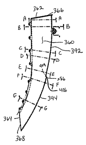
As shown in FIGURES 21 through 25, similar to the above-described embodiments,
the seed tube 356 preferably includes an elongated hollow, tubular member 358
defining an
CA 02557228 1999-O1-25
21
enclosed seed pathway 360. The hollow member 358 has an upper end 362 and a
lower end
364. The upper end 362 of tube 356 defines an ingress area 366 to the
passageway 360. As
will be appreciated, the ingress area 366 is arranged in seed receiving
relation with the seed
discharge area 54 of the seed metering apparatus 32. The lower end 364 of tube
356 defines
an egress area 368 from where seeds are deposited to the ground.
Preferably, and as shown in FIGURES 22 and 23, the tube 356 further includes
an
apertured mounting lug 370 for mounting the tube 358 to the planting unit 14.
The upper
end 362 of the tubular member 358 may be attached to the housing 38 of the
planting unit 14
in a variety of manners. In one embodiment, as shown in FIGURE 2, the upper
end 62 or
362 of the tubular member 358 has a generally square or rectangular cross-
sectional area
which is larger in size than the generally square or rectangular cross-
sectional area of the
seed discharge area 54 of the housing 38. In this embodiment, the upper end of
the tubular
member 358 is attached to the outside of the seed discharge area 54. In an
alternative
embodi~,ent, as shown in FIGURE 21, the upper end 362 of the tubular member
358 has a
generally square or rectangular cross-sectional area which is larger than the
generally square
or rectangular cross-sectional area of the seed discharge area 54 of the
housing 38. In this
embodiment, the seed discharge area 54 of the housing 38 is attached to the
outside of the
upper end 362 of the tubular member 358. While the cross-sectional areas of
the tubular
member 358 are shown to be rectangular, it will be appreciated that the cross-
sectional areas
, may take other shapes such as circular or elliptical.
The hollow member 358 also includes an upper portion 363 and a lower portion
365,
which are generally divided by a monitoring apparatus 386. Generally, the
hollow member
358, and thus the enclosed seed pathway 360, has a first, upper vertically
curved
configuration in the upper portion 363 ofthe member 358, i.e., between the
upper end 362
and the monitoring apparatus 3.86, and a second, lower vertically curved
configuration in the
lower portion 365 of the member 358, i.e., between the monitoring apparatus
386 and the
lower end 364.
It will be appreciated that the ingress and egress areas 366 and 368,
respectively, of
the enclosed seed pathway 360 are disposed in different planes. As shown, both
the upper
and lower vertically curved configurations of the hollow member 358 generally
extend in
21
CA 02557228 1999-O1-25
22
rearward directions opposite to the given forward direction of the seed
metering apparatus
32. While both the upper and lower curved configurations of the hollow member
358 extend
in rearward directions opposite the forward given direction of the seed
metering apparatus
32, the lower curved configuration extends in a more rearward direction than
the upper
curved configuration. The curved configurations of the interior surface of the
hollow
member 358 in the rearward direction tend to nullify the component of
horizontal movement
imparted to the seeds as a result of the forward movement of the planting unit
14 in a given
forward direction.
The tube 356 offers several distinct and different features for controlling
seeds as
they move along the pathway 360. First, at least the interior surface of the
enclosed
passageway 360 has an extremely low coefficient of surface friction in the
range of about
0.02 to about 0.10. In one form of the invention, the tuhe 356 is formed or
molded from a
molybdenum disulfide nylon filled material or similar material having a
coefficient of surface
friction i~ the above range, thus promoting gravitational movement of the
seeds as they
move along the pathway regardless of their size and/or shape. In a preferred
embodiment,
the tube 356 is formed or molded from an aliphatic keytone material, such as a
Carilon~
polymer material manufactured by the Shell Chemical Company. Carilon~ has been
found
to provide excellent wear for pressure-velocity and abrasive applications,
good dimensional
stability, good lubricity and good seed handling properties. Second, the
interior surface of
, the hollow member 358 is specifically configured to minimize seed rattle or
bounce therein
so that control can be maintained over the metering of the seeds as they pass
from the seed
metering apparatus 32 to the ground.
To minimize seed rattle and bounce, as shown in FIGURES 26 through 33, the
ingress opening 366 at the upper end 362 of hollow member 358 preferably has a
larger
cross-sectional area than does the~egress opening 368 at the lower end 364 of
hollow
member 35S. Moreover, the cross-sectional area of the hollow member 358
smoothly
changes as a fi~nction of the length of the hollow member 358. In particular,
from the upper
end 362 to the lower end 364 of the tubular member 358, the generally
rectangular cross-
section of the hollow member 358 decreases thereby providing less and less
space for the
seeds to bounce and move or rattle as they move along the pathway 360.
22
CA 02557228 1999-O1-25
23
In the embodiment shown in FIGURES 26 through 33, more particularly, the
tubular
member 358 includes a rear interior surface or wall 372, a pair of opposed
side interior
surfaces or walls 374 and 376 joined to and extending in a forward direction
from the rear
wall 372, and a front interior surface or wall 378 joined to each side wall
374 and 376. The
terms "front" and "rear" are relative to the path of travel of the planting
unit 14. Thus, the
front wall is in the plane of the given forward direction of the planting unit
14. As shown,
the tubular member 358 is rectangular in cross-section. It will be
appreciated, however, that
the tubular member 358 may have different cross-sectional areas, such as
circular or
elliptical. Thus, if the tubular member 358 had an elliptical cross-section
area, it would thus
have walls similar to that shown in FIGURE 20. Moreover, the walls of the
tubular member
358 do not have to be a single wall. Instead, the walls of the tubular member
358 may be
comprised of a plurality of walls.
As shown in FIGURES 26 through 33, the interior surfaces 372, 374, 376 and 378
smoothlk converge or taper inwardly toward each other as the tubular member
358 extends
from an upper end 362 to the lower end 364, thereby reducing the cross
sectional area of the
enclosed passageway 360 thus limiting the seed bounce and rattle as the seeds
gravitationally
move between opposite ends 362 and 366 of the tubular member 358.
As illustrated in FIGURES 23, 26 and 34, the front wall 378 preferably further
includes an upper portion 392 and a lower portion 394. The juncture of the
upper front wall
_ portion 392 and the lower front wall portion 394 is proximate to an opening
400 provided
for a monitoring apparatus 386. In particular, the upper end 406 ofthe lower
front wall
portion 394 defines an aperture 400 in which a component of the monitoring
apparatus 386
is positioned. Similarly, the rear wall 372 defines an aperture 402 which
separates an upper
portion 396 and a lower portion 398 of the rear wall 372 in which another
component of the
monitoring apparatus 386 is positioned.
Further to minimize seed bounce and rattle, as shown in FIGURES 26, 33 and 35,
a
section of the front wall 378 smoothly tapers and converges into a leading
front or forward
V-shaped edge 380 at the lower end 366 of the tubular member 358. In
particular, the V-
shaped fonvard edge 380 of the passageway 360 is a narrowed and generally
centralized
edge between the side walls 374, 376 of the tubular member 358. More
particularly, the
23
CA 02557228 1999-O1-25
z4
front wall 378 includes slanted surfaces 382 and 384 to form the V-shaped
forward edge 380
along a section of the lower front wall portion 394. The surfaces 382, 384
angularly diverge
in rearward opposite directions relative to each other to form the V-shaped
forward edge
380. As shown in FIGURE 35, the forward edge 380 may have a smooth or rounded
configuration. The surfaces 382 and 384 define an included angle therebetween
and, in the
illustrated embodiment, are integrally joined to and formed with the side
walls 374 and 376.
The included angle defined between the interior surfaces 382 and 384 of the
tubular member
358 ranges between about 60° and about 100°. In a most preferred
form of the invention,
the included angle defined between the surfaces 382 and 384 is about
90°.
In one embodiment, the narrowed V-shaped forward edge 380 is present in a
majority of the length of the front wall 378. In another embodiment, as
illustrated in
FIGURES 27 through 33, the V-shaped forward edge 380 extends upward from the
lower
end 366 only along a section of the lower front wall portion 394. Preferably,
the forward
edge 380. e~.rtends upward from the lower end 366 about one-half of the length
of the lower
front wall portion 394. It will be appreciated, however, that the forward edge
380 may
extend upward from the lower end 366 more than one-half of the length of the
lower front
wall portion 394, but less than the entire length of the lower front wall
portion 394. The
front or forward edge 380 preferably follows the vertically curved
configuration of the lower
front wall portion 394.
. As shown in FIGURE 22, the curved forward edge 380 and the surfaces 382, 384
(see FIGURE 35) extend in rearward'directions, i.e., curve in a direction
opposite the given
forward direction of the seed metering apparatus 32. Accordingly, as the
individual seeds
are released from the metering apparatus and gravitationally move through the
passageway
360 to the lower end 366 of the tubular member 358, the seeds inescapingly
engage and are
controlled by the edge 380 and surfaces 382, 384 of the interior passageway
360. As will be
appreciated, as the seeds gravitationally fall and engage surface 382 they
will be positively
directed by the slanted configuration thereof toward the narrowed and centered
forward
edge 380 of the pathway 360. Similarly, as the individual seeds fall and
engage surface 384
they likewise~will be positively directed by the slanted configuration of
surface 384 toward
the narrowed and centered forward edge of the pathway 360.
24
CA 02557228 1999-O1-25
As stated above, this particular embodiment of the seed tube is designed to
have
curved configurations having different and constant radii between upper and
lower portions
of the seed tube and to have the upper end of the lower portion of the front
wall of the seed
tube being located in a more forward position relative to the lower end of the
upper portion
5 of the front wall. Thus, as shown in FIGURES 23 and 26, the upper front wall
portion 392
and the lower front wall portion 394 have curved configurations of different
and constant
radii. Thus, both the upper and lower front wall portions 392 and 394,
respectively, have a
constant radial configuration. In other words, each of the upper and lower
front wall
portions is in the shape of an arc, which is a portion of the circumference of
a circle. As the
10 upper front wall portion 392 is an arc, it is readily defined by a radius
which would define an
entire circle, where the arc of the upper front wall portion 392 is a section
of that circle.
Similarly, the lower front wall portion 394 is also an arc, that is, again, a
portion of the
circumference of a circle, where the circle, and thus the arc, is defined by a
particular radius.
The radius ofthe arcs of both the upper and lower front wall portions 392 and
394,
15 respectively, may be determined from a single point. In other words, the
center of the arc of
the circle for the upper front wall portion 392 may be the same as the center
of the arc of the
circle for the lower front wall portion 394. If the centers of both arcs are
at the same point,
the radius of the curved configuration of the upper front wall portion 392 is
preferably about
731 mm (28.78 inches) and the radius of the curved configuration of the lower
front wall
20 . portion 394 is preferably about 736 mm.
In addition to the curved configurations having different and constant radii
between
the upper and lower front wall portions, as shown in FIGURE 34, at the point
just above the
opening 400 for the monitoring apparatus 386, the upper end 406 of the lower
front wall
portion 394 is located outside of, or more forward (in the direction relative
to the path of
25 travel of the planting unit 14) than, the lower end 404 of the upper front
wall portion 392.
In other words, just above the monitoring apparatus 386, the upper end 406 of
the lower
front wall portion 394 is stepped forward from the lower end 404 of the upper
front wall
portion 392. As also shown in FIGURE 34, the upper and lower front wall
portions 392 and
394, respectively, preferably have a constant, uniform thickness. Preferably,
the thickness of
the upper and lower front wall portions 392 and 394, respectively, is about 2
mm.
CA 02557228 1999-O1-25
26,
In a preferred form of the invention as shown in FIGURE 34, the seed tube 356
has a
conventional sensor or monitoring apparatus 386 arranged in operable
combination
therewith. The monitoring apparatus 386 is operably arranged in any suitable
manner
between the upper and lower front wall portions 392 and 394, respectively,
ofthe tube 356
to provide a more accurate monitoring of the individual seeds passing through
the
passageway 360. The monitoring apparatus 386 is mounted on the front and rear
walls 378
and 372, respectively, of seed tube 356, in particular, in apertures 400 and
402 of the front
and rear walls 372, respectively. Preferably, the monitoring apparatus 386 is
comprised of a
conventional photodetector including an electric light source 388 and an
electric sensor or
eye 390. As well known in the art, the photodetector is capable of producing
output signals
indicative of individual seeds passing between the light source 388 and the
sensor or eye
390. The output signals are converted to a readout that is preferably provided
to the
operator in a cab region of the tractor (not shown) used to tow the implement
10 (FIGURE
1) across-the field.
Preferably, the eye (not shown) is positioned in the aperture 400 defined in
the front
wall 378, while the light emitting source (not shown) is positioned in the
aperture 402
defined in the rear wall 372. In an alternative embodiment, the eye may be
positioned in the
aperture 402 of the rear wall 372 and the light emitting source may be
positioned in the
aperture 400 of the front wall 378. In this manner, as seeds fall past the
light source and the
. eye, light from the light source directed to the eye is disrupted when a
seed blocks the path
between the light source and the eye; -Once the light is disrupted, the
photodetector
produces output signals which are converted for the operator of the planting
unit 14 which
indicate individual seeds passing between the light source and the eye. In a
most preferred
form of the invention, the monitoring apparatus 386 is operably arranged
relative to the tube
356 such that it is approximately 6 inches or less from the ground.
The co~guration of the interior surfaces of the tubular member 358 are such
that
individual seeds have a tendency and likelihood to slide along the upper front
wall portion
392 to fall past the monitoring apparatus 380, then to slide along the lower
front wall
portion 394 into the V-shaped fonvard edge 380 and then exit the seed tube 356
from the
egress area 368 to the ground. More particularly, seeds fall through the
tubular member
26
CA 02557228 1999-O1-25
27
358 in the following manner. After a seed enters the tubular member 358
through the
ingress area 366, the seed will impact the top of the upper front wall portion
392 and then
slide or ride along the upper front wall portion 392. At the juncture of the
upper front wall
portion 392 and the lower front wall portion 394, i.e., proximate to the
monitoring
apparatus 386, because the upper end 406 of the lower front wall portion 394
is positioned
in a more forward location, or is stepped forward, relative to the lower end
404 of the upper
front wall portion 392, the seed falls past the monitoring apparatus 386,
without hitting the
monitoring apparatus 386, to impact the lower front wall portion 394. No
rearward force is
imparted to the seeds as they move downwardly across the monitor 386. As the
seeds
disengage from the upper front wall portion 392, the seeds continue downwardly
to
promptly return into sliding engagement with the lower front wall portion 394.
This prompt
engagement with the lower front wall portion 394 is aided by the forward
inertial forces (due
the given forward direction of the planting unit 14) on the seeds, which tend
to move the
seeds forward as they disengage from the upper front wall portion 392. The
seed then slides
or rides along the lower front wall portion 394 into the V-shaped forward edge
380 as the
seed travels down the lower front wall portion 394. The front edge 380
contains the seed in
its V-shaped configuration to urge the seed into the front edge 380 rather
than to the sides
382, 384 of the lower front wall portion 394, as described above. The seed
then exits the
tubular member 358 through the egress area 368 and falls to the ground.
Since the various embodiments of the present invention operate in a
substantially
similar manner relative to each other, ~nly a summary of the unique
characteristics of seed
tube 56 will be discussed in detail with the understanding that the other seed
tubes and their
own individual unique characteristics are intended to be encompassed within
the spirit and
scope of the present invention. It was previously noted that the seeds are
released with
substantially equal spacing therebetween from the disk 48 of the seed metering
apparatus 32
at essentially the "3 o'clock" position considering the rotary path of the
disk 48. As such, the
mean direction of the seeds released from the seed metering mechanism is
essentially
vertically downward.
Forming the seed tube of the present invention from any of a class of
materials
including a nylon 6/6 with a PTFE friction modifier added thereto and sold
under the
27
CA 02557228 1999-O1-25
28
tradename "Nylatron GS" or a bay resin with a PAl l l additive added thereto
or other
suitable material advantageously provides the interior surface of the enclosed
seed
passageway 60 with a coefficient of surface friction ranging between about
0.02 and about
0.10. Accordingly, and regardless of the shape or size of the individual seeds
moving along
the pathway 60, the result is that the initial contact of the individual seeds
released and
falling from the seed metering apparatus 32 with the interior surface of the
seed pathway will
have less bounce or rattle than heretofore known. Testing using high speed
photography,
conventional monitoring systems and seed space analyzers has revealed that the
extremely
low coefficient of surface friction provided along the interior seed
contacting surfaces of the
seed pathway causes the individual seeds to slide relative to the contacting
surface of the
pathway rather than bounce or rattle upon contact and produces what may be
best described
as a "deadening" or anti-bounce characteristic. Additionally, the extremely
low coefficient of
surface friction allows the seeds to slide along the interior surface of the
tube without
effecting the speed with which the seeds move as they pass between opposite
ends of the
tube. As will be appreciated by those skilled in the art, deadening the seed
by substantially
eliminating seed rattle and bounce within the tube results in a generally
uniform time it takes
for each individual seed to progress between the ingress and egress ends of
the pathway
thereby enhancing equidistant spacing between adjacent seeds during the
planting operation.
Additionally, in a preferred embodiment, the tube is formed or molded from an
aliphatic
, keytone material, such as a Carilon~ polymer material manufactured by the
Shell Chemical
Company. Additives such as carbon fibers, carbon polymers or stainless steel
fibers may be
added to the Carilon~ resin to make the seed tube resistant to static charge
build-up or to
make it electrically conductive. Carilon~ has been found to provide excellent
wear for
pressure-velocity and abrasive applications, good dimensional stability, good
lubricity and
good seed handling properties. ..
The downwardly curved configuration of the interior surface of the seed
passageway
60 furthermore serves to reduce seed rattle and bounce as the individual seeds
gravitationally
move between opposite ends and through the tube 56. The rearwardly curved
configuration
of the interior~surface of the seed pathway tends to nullify the component of
horizontal
movement imparted to the seeds as a result of the forward movement of the
implement in a
28
CA 02557228 1999-O1-25
29
given forward direction. Moreover, the rearwardly and downwardly curved
configuration of
the interior surface of tube 56 tends to minimize the angle of incidence of
seed contact with
the interior surface of the seed pathway 60.
As schematically illustrated in FIGURE 3, a dash line 57 represents the mean
path of
seeds released from the seed metering mechanism 32. Upon release from the seed
metering
mechanism 32, seeds tend to fall essentially vertically downward through the
ingress end 66
of the tube 56 and into initial contact with the interior surface of the seed
pathway 60.
Because of the curvature of the interior surface of the pathway 60 (and
partially because of
the significantly lowered coefficient of surface friction), the angle of
incidence established
between the path of the falling seed and the vertical slant of the interior
surface is relatively
small. As will be appreciated by those skilled in the art, the continuous
rearward and
vertically slanted curvature of the interior surface of the pathway 60 tends
to further reduce
the angle of incidence established between the seed contact and the interior
surface of the
pathway thus furthermore reducing the seed rattle and bounce as the individual
seeds
gravitationally travel along the pathway 60.
Configuring the seed tube with a narrowed front edge 80 extending upwardly
from
the discharge end 68 of the tube 56 and along the portion of the enclosed
pathway 60 (either
along a section of the lower front wall or a majority of the front wall)
furthermore serves to
reduce seed rattle and bounce as the seeds move along the pathway 60 thus
promoting
control over the seeds gravitationally moving along the pathway and thereby
promoting the
ability to effect equidistant spacings between adjacent seeds planted in the
furrows.
According to the present invention, the narrowed front edge 80 extends beneath
and across,
in a fore-and-aft direction, the ingress end 66 of the seed tube thus yielding
further control
over the gravitationally moving seeds as they pass between opposite ends of
the seed tube.
The angularly diverging surfaces 82, 84 rearwardly extending from the front
edge 80
furthermore serve to positively direct the seeds toward a predetermined path
of movement
while minimizing seed bounce and rattle as the seeds move along the pathway.
Because the
narrowed front edge 80 is generally centralized in a lateral direction
relative to the pathway,
the discharge of seeds from the tube ~6 tends to remain constant thus yielding
predictable
and generally uniform discharge or dispensing of the seeds into the furrow in
the ground.
29
CA 02557228 1999-O1-25
30 ,
Moreover, providing at least the interior surface configuration of the tube
with an extremely
low coefficient of contact surface friction allows the seeds, regardless of
their size or
configuration, to move along and contact the interior surface with no
appreciable loss in
speed as they move between increase and egress ends of the tube.
From the foregoing, it will be observed that numerous modifications and
variations
can be egected without departing from the true spirit and scope of the novel
concept of the
present invention. It will be appreciated that the present disclosure is
intended as an
exemplification of the invention, and is not intended to limit the invention
to the specific
embodiment illustrated. The disclosure is intended to cover by the appended
claims all such
modifications as fall within the scope of the claims.