Note: Descriptions are shown in the official language in which they were submitted.
ak 02557286 2012-11-22
1
ADJUSTMENT OF TELESCOPICALLY MOVABLE ELEMENTS
Technical Field
The invention related to a locking arrangement with two
elements that are slidable into one another such as a
shaft for a tool where the length is adjustable. The
shaft has a locking member at an outer element of one
end. The locking member is maneuverable with a
maneuvering member that is at a distance from the locking
member in a direction towards the other end on the outer
element via an affecting member that is slidable along or
rotatable about an axis that is parallel to the
longitudinal axis of the outer element.
State of the Art
In WO 02/18802A1 an arrangement is described that is
mainly adapted for a tool shaft that has a telescopic
function. The arrangement includes a tubular shaped
element, an inner and an outer, that can be locked
relative to one another. The locking is done with the
help of a locking member that is securely mounted on the
end of the outer element. The opening of the lock is
done with the help of a maneuvering member at the other
end of the outer element. The transfer of the opening
forces is done with the help of an affecting member
between the two ends on the outer element. In the
description a number of different variations of affecting
members are suggested. The preferred embodiment of the
affecting member is a thin steel band that is inserted
between the inner and the outer elements.
ak 02557286 2012-11-22
2
This embodiment functions well but is costly to produce.
Not only is the cost for the band that requires openings
and cutting high but also the mounting is cumbersome and
time-consuming. None of the remaining variations of the
affecting members that are hitherto known result in any
substantial reduction of the production costs. In
addition to the locking details, the tube system accounts
for a major portion of the costs. Especially the outer
element is costly. One reason is the demanding
requirements of durability and the surface on the outer
tube. The outer element is usually manufactured of
hardened aluminum that has been surface treated in a
certain way. It must be able to endure normal handling
without being damaged which requires a thickness of at
least one millimeter. Furthermore, it is desirable that
the surface is painted since it is used for gripping.
Anodized surfaces are also used but are experienced as
being cold to hold.
Description of the Invention
The object of the present invention is to achieve an
arrangement according to the ingress that makes it
possible to manufacture at substantially lower costs
compared to earlier known variations.
This object is achieved by the locking arrangement that
has two elements that are slidable into one another such
as a shaft for a tool where the length is adjustable.
The shaft has a locking member at an outer element of one
end. The locking member is maneuverable with a
CA 02557286 2012-11-22
3
maneuvering member that is at a distance from the locking
member in a direction towards the other end on the outer
element via an affecting member that is slidable along or
rotatable about an axis that is parallel to the
lengthwise axis of the outer element. The affecting
member includes a tube that is made of a polymeric
material. The tube encloses the outer element and the
outer element has a thin walled, untreated tube of metal,
preferably hardened aluminum.
The invention will be described in more detail with
reference to the attached drawings that are intended to
explain but not limit the invention whereas
Fig. 1 is a shortened side view showing a tool shaft with
an arrangement according to the invention.
Fig. 2 is a side view showing mainly the locking member.
Fig. 3 is a side view showing details of the opening
system of the lock.
Fig. 4 is a partly opened side view showing the upper
part of the arrangement according to Fig. 1 in a locked
position.
Fig. 5 is a partly opened side view showing the lower
part of the arrangement according to Fig. 1 in a locked
position.
CA 02557286 2012-11-22
4
Fig. 6 is a partly opened side view showing the upper
part of the arrangement according to Fig. 1 in a released
position.
Fig. 7 is a partly opened side view showing the lower
part of the arrangement according to Fig. 1 in a released
position.
Fig. 8 shows a side view of an arrangement with a pulling
maneuvering member, in a closed position.
Fig. 9 shows an arrangement according to Fig.8, in an
open position.
Fig. 10 is a side view that mainly shows the locking
member.
Fig. 11 is a cross sectional view of the locking member
according to Fig. 10 in the direction of the arrows A.
Fig. 12 is a side view that shows a wedge, affecting
member and maneuvering member.
Fig. 13 is a view of the component according to Fig. 12
seen from below according to European view positioning.
Fig. 14 is a partly opened side view that shows the
locking member according to Fig. 10, the arrangement
according to Fig. 12, mounted on the outer element that
is in a locked position with an inner element.
Fig. 15 shows the arrangement according to Fig. 14 in a
released position.
ak 02557286 2012-11-22
Fig. 16 is a partly opened side view that shows a locking
member mounted on an outer element and with a secured
locked inner element where the wedge has an alternative
5 shape.
Fig. 17 is an arrangement according to Fig. 14 with the
exception that the wedge is turned in the opposite
direction.
Fig. 18 is a side view showing a vacuum cleaner shaft
with a bent tube and hose and with a locking arrangement
according to the invention.
Fig. 19 is a partly opened enlargement of the encircled
portion of Fig. 18.
Fig. 20 is a partial side view showing the lower part of
the vacuum cleaner shaft with a vacuum cleaner nozzle
mounted thereon.
Fig. 21 is a side view according to the arrangement in
Fig. 18 and shows an alternative embodiment of the
affecting member and the maneuvering member.
Fig. 22 shows a partial cross section of an upper part of
a telescopically adjustable shaft.
Fig. 23 shows a partial cross section of a lower part of
the shaft according to Fig. 22.
ak 02557286 2012-11-22
6
Fig. 24 is a partially opened side view of a wedge
arrangement.
Fig. 25 is a partially opened side view showing a sleeve
with clamping jaws.
Fig. 26 is a cross section of the sleeve according to
Fig. 25 along the cross sectional line A-A in which the
view position is according to European drawing standards.
Fig. 27 is an enlarged portion of an upper part according
to Fig. 22.
Fig. 28 is an enlarged portion of a lower part according
to Fig. 23.
Fig. 29 is an upper part according to Fig. 27 in a
released position.
Fig. 30 is a lower part according to Fig. 28 in a
released position.
Fig. 31 is a partially broken out side view showing a
clamping jaw.
Fig. 32 is a top view showing the clamping jaw according
to Fig. 31, in which the view position is according to
European drawing standards.
Figs. 33, 34, 35 and 36 are views shown a sleeve with an
integrated wedge in which the view position is according
to European drawing standards.
cp, 02557286 2012-11-22
7
Figs. 37 and 38 are view showing a pulling bar in which
the view position is according to European drawing
standards.
Fig. 39 is a side view showing the sleeve according to
Fig. 33 including an attached clamping jaw and pulling
bar according to Figs. 31 and 38.
Fig. 40 is a opened side view showing the shortened shaft
with the locking arrangement according to Fig. 39 in a
locked position.
Fig. 41 is a opened side view showing an arrangement
according to Fig. 40 in a released position.
Fig. 42 is a partial front cross section shown a lower
sleeve put over an upper sleeve with a pulling rod.
Fig. 43 is a side view of the arrangement according to
Fig. 42 in a view position according to European drawing
standards.
Fig. 44 is a side view showing a clamping jaw.
Fig. 45 is a cross section of the clamping jaw according
to Fig. 44 along the cross sectional line A-A, in a view
position a view position according to European drawing
standards.
Fig. 46 is a front view of the arrangement according to
Fig. 42 with a clamping jaw mounted thereon according to
ak 02557286 2012-11-22
8
Fig. 44 where the arrangement is inserted into an opened
tube and is in a locked position.
Fig. 47 is an arrangement according to Fig. 46 in a
released position.
Fig. 48 is a front view of a clamping jaw with the wedge
surfaces turned away.
Fig. 49 is a side view of the clamping jaw according to
Fig. 48 in a view position according to European drawing
standards.
Fig. 50 is a view from above of a clamping jaw according
to Fig. 48 in a view position according to European
drawing standards.
Fig. 51 is an opened side view of a lower sleeve of a
lock.
Fig. 52 is a cross section of the sleeve according to
Fig. 51 along the cross sectional line A-A in a view
position according to European drawing standards.
Fig. 53 is a cross section of the upper sleeve.
Fig. 54 is a view from above of the sleeve according to
Fig. 53 in a view position according to European drawing
standards.
Fig. 55 is a partially opened side view of the locking
arrangement in a locked position.
ak 02557286 2012-11-22
9
Fig. 56 is an arrangement according to Fig. 55 in a
released position.
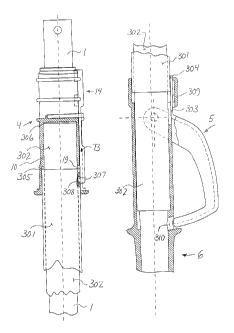
Fig. 1 shows an arrangement of a tool shaft that includes
an inner element 1 with a connection opening 2 for
connecting a suitable tool. The inner element 1 is
removably locked to the outer element 3 with the help of
a locking member 4 that is enclosed by a protection
housing 71. The lower part of the outer element 3 has a
handle mounted thereon that has swingable peg 70 on which
a U-shaped maneuvering member 5 is rotatably hooked. The
outer element has an inner metal tube and an outer
plastic tube that encloses the metal tube. The plastic
tube has the double function to provide a desirable
surface and also to be an affecting member. The opening
forces of the maneuvering member 5 with the help of the
plastic tube is transferable to the locking member 4
which function will be explained in more detail below in
the description. Fig. 2 shows the locking member in a
side view. It is substantially identical to the locking
member shown in figures 2-5, 39-41 and 45 of WO
02/18802A1. The difference is that the attachment collar
10 is extended with a flange forming a space 305 in which
the outer tube can freely move. The flange has a groove 19
for receiving an engagement tap according to the
following description. The opening system shown in Fig.
3 includes a wedge 14, an outer plastic tube 301 and a
maneuvering member 5. The wedge 14 includes, according
to known technology, two wedge elements that cooperate
with corresponding wedge grooves in the groove 13 (in
Fig. 2) and an extension 73 that is terminated by an
ak 02557286 2012-11-22
engagement peg 307. The outer tube 301 is preferably
made of extruded polypropylene which can be reinforced
and colored. This means that a heat insulated, impact
durable
5 surface is provided that has the desired colors. The
cost for this outer tube is comparable to the cost for a
varnish layer on an aluminum tube. The tube 301 has its
upper end including an opening 308 into which the
engagement peg 307 is inserted. The described locking
10 member requires about 120 N in pulling force. However,
the dimensions of the opening 308 that are here
considered, the pressure on the opening despite this so
low that the polypropylene material is not overloaded
during the relatively short opening process. The
maneuvering member 5 that is shown in Fig. 3 is
preferably made by injection molding in a suitable
plastic material and is thus shaped like a bent U-profile
with two flanges 61. Through holes 26 are defined in the
flanges. These holes 26 define a rotation center for the
maneuvering member 5. The maneuvering member is provided
with an extension 303 that is made in the same piece as
the maneuvering member which is very advantageous. The
extension 303 includes at its uppermost end a protrusion
304 that can be provided with an engagement peg that is
hooked into the corresponding holes in the tube 301. It
is preferred though that the protrusion 304 has a smooth
underside that is welded on the tube 301. Fig. 4 shows
how an inner tube 1 is inserted through the locking
member 4 and through an inner metal tube 302 preferably
made of a hardened aluminum. The inner metal tube 302 is
inserted into the opening 306 at the attachment collar 10
and thus securely attached to the locking member 4. At
CA. 02557286 2012.-11-22
11
its lower end, the tube 302 is inserted into the
corresponding bottom hole in the handle 6, according to
Fig. 5. The tube 302 has the function of keeping the
handle 6 together with the locking member 4 and
thereafter to absorb axial forces and rotating and
bending momentum. Further, the tube 302 has a channel
for the inner tube 1. The outer plastic tube 301 is put
over the tube 302 with a certain play that enables axial
sliding of the tube 301 relative to the tube 302. The
upper end of the tube 301 is inserted with a play into a
tube shaped space 305 in the attachment collar 10.
Through an opening that is in the form of a track 19 in
the attachment collar 10 is the engagement peg 307, on
the extension 73 of the wedge 14, hooked in the opening
308 of the tube 301. The wedge 14 can thus be drawn in
an axial direction by the tube 301. The wedge 14 is thus
held in place by the protection housing 71 (not in
figure) that permits the wedge to move with a certain
play without falling out of the track 13 (according to
Fig. 2). In the lower part, the tube 301 is inserted
into a tube shaped flange in the handle 6 with a certain
play. The flange is equipped with an axial groove 309
that provides a space for the protrusion 304 on the
extension 303 of the maneuvering member S. During the
opening process, the protrusion 304 can therefore freely
move in the axial direction but still be supported on the
sides so that the rotation momentum on the tube 301 is
taken up in the handle 6 and is transferred via the tube
302 to the locking member 4. The locking member 4, when
in the locked position, transfers the rotation momentum
to the inner element 1. As mentioned earlier, it is
preferred that the protrusion 304 is welded on the tube
ak 02557286 2012-11-22
12
301. This is suitably done by using ultrasound welding
after the components have been mounted. In this way, the
tolerances of the dimensions of the included components
that affect the length of the opening of the wedge 14 can
be eliminated. The groove 309 is upwardly open so that
the protrusion 304 can be inserted therethrough.
Further, the groove 309 can be provided with an outward
hole, in the right direction on Fig. 5 (not shown), so
that the weld spot can be inserted therethrough. The
maneuvering member is put over outside swingable pegs.
An upper portion of the maneuvering member has a clamp
that during the opening process is turned into the groove
310 in the handle 6. The handle 6, as in Fig. 5 is only
partly shown, is preferably made in one piece by
injection molding in a suitable polymeric material such
as polypropylene.
Figs. 6 and 7 show an upper and lower part of the
arrangement in a released position. When the maneuvering
member 5 is pushed in the direction of the arrow J the
extension 303 is pulled in the direction of the arrow K.
The extension 303 is thus bent. This does not lead to
fatigue problems if a suitable plastic material is used.
The extension 303 pulls the tube 301 in the direction of
the arrow K. Thus the wedge 14 is pulled in the
direction of the arrow L and the locking member 4 is
released so that the inner element 1 can be freely slide
and be turned in the direction of the arrows M and N,
respectively. When the maneuvering member 5 is released
the spring element in the locking member 4 returns the
system, the wedge 14, the tube 301 and the maneuvering
ak 02557286 2012-11-22
13
member 5 in the unaffected position, according to Fig. 4
and 5.
An important aspect of the present invention is the
surprising but advantageous effect of the combination of
the inexpensive plastic tube 301 and the inexpensive
metal tube 302 where the plastic tube has the double
function of providing a desirable surface for the purpose
and also be an affecting member with which help the
opening forces from the maneuvering member 5 can be
transferred to the locking member 4. The plastic tube
301 can be relatively thin walled, about 1.5 mm is
preferred if the wedge 14 is to be attached to the tube
301 according to the description above. In the case when
the extension 73 of the wedge 14 is welded on the tube
301 the thickness of the piece can be reduced. The
plastic tube has a low weight and cost but provides
despite this a powerful impact protection for the metal
tube 302 that can therefore be thin walled and thus have
a low weight and cost. It is especially advantageous for
the production cost that no surface treatment of the tube
302 is required. The total effect of this inclusive the
substantial reduction of the assembly time is that the
production costs are 30-40 ,- compared to know technique.
The invention has in the above description been used on a
special type of locking member but can of course be used
on a wide range of types of the locking member that
permit maneuvering of the distance of the locking
function. Further, the invention can be further varied
within the scope of the patent claims that is obvious to
the person of ordinary skill in the art.
ak 02557286 2012-11-22
14
The invention can within the scope of the patent claims
be further varied as follows. Fig. 8 and 9 show side
views of an arrangement with a pulling maneuvering member
in a closed and open position, respectively. The
arrangement includes as described earlier an inner
element 1 which can be provided with a connection hole 2
for attachment of a suitable tool. The inner element 1
is removably locked to the outer element 3 with the help
of a locking member 4 enclosed by a protection housing
71. The outer element includes an inner metal tube 302
and an outer
plastic tube that enclose the metal tube. The plastic
tube, that has the function according to the earlier
description, can be terminated by a pulling flange 5
which serves as the maneuvering member. Without the
pulling flange a major part of the tube 301 can function
as the maneuvering member.
A pulling maneuvering member assumes that the transfer
forces are substantially lower than 120N. A lower
maneuvering force on the locking type that is her
described can be achieved by reducing the wedge angle on
the wedge 14. Empirical tests have shown that an angle
between the wedge surfaces of about 10 degrees and with a
polyamide plastic in the wedge and acetal plastic in the
opposing surfaces the maneuvering force can be reduced to
about 30-40 N without causing the components to be stuck.
This is an easily applicable force for the grip that is
here considered. For shape-dependent lock types the
pulling forces can be further reduced.
ak 02557286 2012-11-22
When this arrangement is used as a tool shaft the user
grabs the handle with one hand and the plastic tube 301
with the other hand. The arrangement is then usually
turned so that the handle 6 is on top. When working with
5 a tool, such as mopping of a floor with a mop shaft the
upper hand rests on the handle 6 while the lower hand is
placed in a suitable position on the tube 301. This
position depends on the individual and on the work
position. To be able to achieve a sufficient leverage
10 arm a minimum distance of about 20 cm is required. For a
tooling shaft this means that there generally is a
portion of the upper part of the shaft, below the handle,
that is seldom gripped by the user. This of course
assumes that the length of the shaft can be adjusted.
15 The plastic tube 301 can thus be terminated a bit below
the handle 6 which saves weight and reduces the
production costs even if some type of surface treatment
of the visible part of the tube 302 is desirable.
During adjustment, the operator moves his lower hand up
towards the maneuvering member 5 and pulls this in the
direction of the arrow K against resistance from his
upper hand on the handle 6. The locking member 4 is thus
released so that the inner element 1 can freely be slid
in the direction of the arrow M. Because the force
requirement is relatively low, the operator can also
choose to keep his lower hand in the grip position about
the tube 301 and pull this upwardly. The adjustment can
thus be done without changing the grip. Even if the
operator moves his lower hand to the pulling flange 5
this is done with an almost unchanged grip because the
hand can control the shaft while the hand glides along
ak 02557286 2012-11-22
16
the tube 301. The maneuvering during the ongoing work
can thus be done substantially easier compared to using a
maneuvering member for the upper hand. During locking,
the operator releases the pulling grip about the tube
301. In this way, the spring element in the locking
member 4 returns the system, the wedge 14, the tube 301
and the maneuvering member 5 to an unaffected position.
The maneuvering distance for this described locking type
with the above mentioned wedge angle is about 20 mm. The
space between the maneuvering member 5 and the handle 6
of course makes it possible to use long maneuvering
distances. This is a great production technical
advantage because the locking arrangement is insensitive
to tolerances on the cutting length of the tube. An
additional production technical advantage is the simple
construction with few easily assembled components.
The invention can be varied in a many different ways
within the scope of the patent claims. For example, the
tube 301 can be shorter than what is shown in Figs. 8 and
9. For example, one could imagine that the tube is made
to the protection housing 71 by letting the protection
housing be axially shiftable and function as the
maneuvering member 5. Even if a polymeric material is
preferred the tube 301 can of course be made of other
materials such as metal. A low maneuvering force makes
it possible to use a material with a relatively low
stiffness and durability such as a renewable material.
Further the tube 302 can be made by another material than
metal such as a polymeric material or a renewable
material. Further the maneuvering member 5 can be varied
in many different ways both with regard to the
ak 02557286 2012-11-22
17
maneuvering principles and the geometrical shape. These
and other variations that are obvious to the person of
ordinary skill in the art are included in the patent
claims.
The invention can also be used on tool shaft in the form
of telescopically adjustable vacuum cleaner shafts that
has an inner and outer tube shaped elements. Due to the
requirement of a free passage of air through the inner
element only locking member that affect the outer mantel
surface of the inner element can be used in this
application. The locking member that is dominating on
the market is of a form locking type that takes advantage
of impressed locking grooves on the inner element. This
type of lock has many drawbacks. For example, the
locking grooves constrain the air flow. Another drawback
is that the locking grooves that cooperate with locking
bodies that glide against the locking grooves during
adjustment of the shaft length. This gives rise to a
disturbing noise. Another drawback is that the shaft
length can not be adjusted in an infinitely variable way.
An addition drawback is that the form lock required that
the inner and outer elements, respectively, are
permanently fixed relative to one another with regards to
the turning with the help of longitudinal grooves. It is
thus not possible to adjust the angle between the inner
and the outer elements which can be desirable because the
vacuum cleaner hose if often connected to the vacuum
cleaner shaft with the help of a bent tube that sometimes
is in the way. An additional drawback is that the
locking grooves as well as the longitudinal grooves are
costly to produce.
ak 02557286 2012-11-22
18
These drawbacks are removed with the arrangement
according to Figs. 10-17.
The locking member, according to Figs. 10 and 11 includes
jaws 9 with inside friction surfaces 12, spring element
11 and attachment collar 10 that are substantially
identical to the locking member described in WO
02/18802A1 according to Figs. 2-5, 39-41 and 45. The
difference is that the attachment collar 10 is extended
with a flange that has an outer mantle surface that
includes an axially directed guide groove 400 for an
affecting member 7 according to Figs. 12 and 13. The
affecting member 7 is at one end provided with an
extension 73 that is attached to a wedge 14. In its
other end the affecting member 7 is attached to a
maneuvering member 5 that is adapted to be shifted in an
axial direction by the thumb of the operator. An
outwardly protruding shelf 401 thus provides a support
that forms a shape-dependent gripping surface so that the
maneuvering member can be adjusted without any
difficulty. The difference between the known techniques
is also that the jaws 9 here includes outwardly directed
lips 402 that are provided with oppositely directed wedge
surfaces 203. These wedge surfaces 203 may be plane
according to known techniques or be bent according to
Fig. 10. These wedge surfaces 203 cooperate with
outwardly directed wedge surfaces 204 on the wedge 14 in
Fig. 12. Because the angle between the wedge surfaces
204, when using a suitable material, can be small
according to the earlier description so that the required
maneuvering force is so small that it can easily be
achieved by the thumb of the operator. Bent wedge
surfaces 203 make it possible to use varied wedge angle
ak 02557286 2012-11-22
19
of the wedge 14. It can, for example, be desirable to
have a great2er wedge angle in the beginning of the
maneuvering and a smaller wedge angle at the end of the
maneuvering distance. This, a constant or a degressive
maneuvering force may be obtained which may be desirable
for ergonomic reasons. The sliding of the wedge 14
gliding between the outwardly directed jaws 402 means
that the tangentially directed force derived from the
wedge towards the jaws 9 affect on a bigger radius R,
according to Fig. 11, compared to the situation when
known techniques are used. In this way, a greater
exchange of the maneuvering force compared to known
techniques is achieved. The combination of the bigger
radius, the suitable material selection and the smaller
wedge angle make it possible to include an arrangement in
the locking member where the exchange of the maneuvering
force can be achieved without outer leverage arms or
other outer force enhancing arrangements. This is
particularly advantageous because the manufacturing is
made simpler due to the fewer parts and lower tolerance
requirements. Further, more freedom for use of
difference control principles and different design shapes
of the maneuvering member, such as a thumb controlled
maneuvering member according to the description above.
This is not obvious in view of known techniques.
Fig. 14 shows an outer element 3 inserted into the
attachment collar 10 of the locking member 4 and is fixed
to this attachment collar in a suitable way. The outer
element 3 here includes an outer tube of a vacuum cleaner
tube that is preferably turned downwardly to be connected
to a vacuum cleaner nozzle. The inner element 1 is then
ak 02557286 2012-11-22
turned upwardly towards the operator to be connected to a
vacuum cleaner hose. The inner element 1 is inserted
into the outer element 3 and is, as shown in Fig. 14,
locked, in a known manner, to the jaws 9 of the locking
5 member 4. The jaws 9 and the cooperating components are
protected by the enclosing housing 71. Between the jaws
9 and the housing 71 is a space in which the wedge 14 and
the attached components may glide. When it is desired to
adjust the length of the vacuum cleaner shaft, the
10 operator grips the outer mantle surfaces on the housing
71 and the attachment collar 10 and slides thereafter the
maneuvering member 5 in the direction of the arrow K with
the support of the outwardly protruding shelf 401,
according to Fig. 15. The wedge 14 then glides between
15 the outwardly directed lips 402 so that the jaws 9 are
pressed to separate. The outer element 3 can thereafter
be adjusted to a desired position in the directions of
the arrows M and N relative to the inner element 1. This
presumes that the operator firmly holds the inner element
20 with the other hand which is a common way of adjusting
the length of the vacuum cleaner tube.
Figs. 16 and 17 show some other embodiments that are
considered in connection with vacuum cleaner shafts.
Fig. 16 shows a locking arrangement with a double
directed wedge 14 that is attached to the inner mantle
surface of the housing 71. When the operator grips the
housing 71 and shifts it in the direction of the arrow K,
the wedge 14 is also shifted in the direction of the
arrow K. This, the lock is released and the outer
element 3 glides, under the influence of the forces from
the wedge surfaces, relative the inner element 1 in the
ak 02557286 2012-11-22
21
same direction as the adjustment direction of the housing
71. The housing 71 here form the maneuvering member 5.
This adjustment of the relative position of the outer
element 3 relative to the inner element 1 can, thanks to
the double directed wedge, be done in both directions.
Fig. 17 shows an embodiment where the maneuvering member
5, when the lock is released, shifts in a direction
towards the free end of the inner element 1. This, the
inner element can be turned downwardly which sometimes is
preferred in connection with vacuum cleaner shafts.
The invention has here been described in connection with
vacuum cleaner shafts but can of course be used in
completely different applications where an inner and an
outer element can releasably be locked relative to one
another.
In connection with applications of the invention on
telescopically adjustable vacuum cleaner shafts are the
embodiments in Figs. 18-21 especially suitable.
The described combination of the invention of the locking
member affecting the outer mantle surface of the inner
element and the affecting member and the maneuvering
member that is outside the outer element are very
suitable for telescopically adjustable vacuum cleaner
shafts. In this way the inner element can have a free
passage for air while at the same time the mantle surface
of the outer element does not have to be opened but can
seal against the inner element. The inner element 1 can
at its lower end be provided with a cone 403 or be
prepared in another suitable way to receive a vacuum
ak 02557286 2012-11-22
22
cleaner nozzle such as the nozzle 405 that has an
extension 404 according to Fig. 20. At its upper portion
the inner element 1 is suitably provided with a seal 408
that seals against the inner tube 302 according to Fig.
19. It is preferred that the seal is easily moved so
that the inner element 1 falls down by its own weight at
least with the help of the weight of the vacuum cleaner
nozzle when the locking member 4 is released. The inner
element 1 is thus shiftable inside the inner tube 302.
In the lower part of the tube 302, a locking member 4 is
attached. The locking member can releasably hold the
inner element 1. In the upper part of the inner tube 302
a bent tube 406 may be inserted in a known manner. The
bent tube 406 may suitably terminate into a vacuum
cleaner hose 407. An affecting member in the form of an
outer tube 301 partly encloses the inner tube 302 with a
certain play. On the upper part of the tube 301 is a
maneuvering member in the form of a pulling flange 5
arranged. The lower part of the tube 301 is connected to
the locking member 4 so that the locking member 4 is
opened when the tube 301 is pulled in the direction of
the arrow K. Commonly available locking types on the
market can be used as the locking member but it is
preferred that a friction lock according to the invention
is used. In this way the outer tube 301 can be attached
to the housing 71. The housing 71 enclosed in this case
the locking member 4 and is axially shiftable about the
locking member with a certain play. A wedge 14 can be
attached to the inner mantle surface of the housing 71,
according to Fig. 16. In this application it is thus
preferred that the wedge 14 is operable in one direction
so that the release of the locking member 4 can be
ak 02557286 2012-11-22
23
achieved by an axial shift of the outer tube 301 in the
direction of the arrow K. In the alternative, the
extension 73 of the wedge 14, according to Fig. 12, be
made more extended and be attached to the outer tube 301.
In both cases, the locking member is released by the
operator pulling the pulling flange 5 or the outer tube
301 upwardly, in the direction of the arrow K. This
leads to the inner element being released and can be
shifted in the direction of the arrows M. It is then
also possible to rotate the inner element relative to the
locking member 4. The wedge can of course also be
turned, according to Fig. 17, so that the opening is done
by the operator pressing the tube 301 in the direction
that is opposite to the direction of the arrow K. This
arrangement makes it possible to quickly and reliably
adjust the length of the vacuum cleaner shaft without
requiring the operator to bend down which is very
desirable.
Fig. 21 shows a vacuum cleaner shaft where the affecting
member 7 includes a bar that runs adjacent to the tube
302. The cross section of the bar can have geometry such
that it partly encloses the tube 302. If the enclosing
angle is more than 180 degrees the bar can be snapped
onto the tube 302 which can be an advantage during
assembly. The bar can also be shaped so that it includes
one or many components that enclose the tube 302 more
than 180 degrees and between these components have a
smaller cross section. It is suitable that the
maneuvering member 5 is attached to the upper part of the
bar 7. In all embodiments the bar runs without much
friction against the tube 302 during axial shifting in
ak 02557286 2012-11-22
24
the direction of the arrow K. It has then the same
function as the tube 301 but can be manufactured with
less material. The advantage with a completely covered
tube 301 is, as mentioned earlier, that the requirement
of a surface treatment of the tube 302 is reduced and the
tube 302 can be made of a thinner material.
Is it from many aspects suitable for telescopically
shiftable elements with locking members that influence
the outer mantle surface according to the above
description.
In certain case though it is desirable with a locking
member that affects the inner mantle surface, according
to Figs. 22-41.
The upper part shown in Fig. 22 and in Fig. 29 of the
telescopically adjustable shaft includes a tube shaped
handle 6 that has an opening on one side (to the right in
the figure) into which the maneuvering member 5 is
inserted. The maneuvering member 5 is partly shown as
opened and has a gripping portion that has a U-shaped
cross section. The upper part of the maneuvering member
includes an extension 303 that has a peg shaped
protrusions 304. These protrusions are snapped into the
corresponding openings on the mantle surface of the
handle 6. The maneuvering member 5 is manufactured by
injection molded plastic and when a suitable material is
selected the extension 304 can serve as a hinge according
to the earlier description. The maneuvering member 5
includes also an arm 410 that is made from the same piece
as the maneuvering member. The arm 410 is preferably
provided with an opening to receive an upper hook shaped
ak 02557286 2012-11-22
portion 411 on the bar shaped affecting member 7. This
affecting member 7, preferably is made from a round bar
of aluminum, is at its lower part connected to a locking
member 4 at the lower part of the shaft according to Fig.
5 23.
The locking member 4 is now described in more detail with
reference to the Figs. 24, 25, 26 and 28. Fig. 24 shows
a cylinder 413 that has an outer mantle surface that
10 includes a rise in the form of a wedge 14. The cylinder
413 that is preferably made of an injection molded
polyamide plastic is provided with an opening with a
lower end to receive a compression spring. The lower end
is provided with a smaller through put opening 429. The
15 wedge equipped cylinder 413 is intended to cooperate with
a sleeve 414 according to Figs. 25 and 26. The sleeve
414 is preferably made of an injection molded acetal
plastic and include at its upper part a tube shaped pole
417 that is intended to be inserted and be securely
20 attached to an inner element 1. The pole 417 includes an
upper end with a smaller through put opening 418. This
end is intended to serve as a counterpart for a
compression spring. The sleeve 414 includes also a tube
shaped intermediate portion 428 which mantle surface is
25 intended to serve as a guiding surface for the
surrounding outer element 3. This intermediate portion
428 is broken up by a through put groove 416 which groove
is intended to serve as a groove for the wedge 14. The
sleeve 414 includes at its lower part a pair of jaws 9.
The jaws are made in one piece with the sleeve 414 and
are connected to the intermediate portion 428 via a
relatively narrow neck 415. The jaws 9 are separated
CA. 02557286 2012.-11-22
26
from each other by a wedge shaped groove 13 that forms
oppositely directed wedge surfaces 203 on each jaw 9,
respectively. In the sleeve 414 there is an axially
directed opening arranged that runs from the lower end of
the jaws 9 to the upper end of the pole 417. This
opening is so shaped that the cylinder 413 can glide in
it in an axial direction with a certain play. The jaws 9
include outer surface layers 12 of a suitable friction
material. It is preferred that the surface layers 12
have rubber like material sprayed thereon that has a
suitable hardness. A taped rubber layer can also be
considered. The surface layers 12 only cover a portion
of the circumference of the jaws 9 to make sure a free
passage for the outer element 3 when the lock is
released. The surface layers 12 also form a broken
mantle surface to a cylinder which has an outer diameter
that, in the unaffected position, is slightly smaller
than the inner diameter of the outer element 3. To
further ensure the free passage for the outer element 3
when the lock is released the jaws 9 can also include a
ring shaped resilient element 11 that has a compressing
effect. The element is put over the jaws 9 and down into
the grooves at about half of the height of the jaws. The
springing element 11 is mounted before the addition of
the surface layers 12. During the mounting of the
cylinder 413 the upper part of the cylinder 413 is
inserted from below into the axially directed opening in
the sleeve 414. When the wedge 14 is thus stopped by the
jaws 9 they can spring outwardly so much that the
cylinder 413 with its wedge 14 can pass so that the wedge
14 is fit into the tracks 13 and 416. The wedge 14 can
ak 02557286 2012-11-22
27
possibly be provided with a suitable phase to make
assembly easier.
Fig. 27 shows how the inner element 1 is inserted into an
opening in the lower part of the handle 6 and permanently
attached thereto in a suitable way. Further, the outer
tube 301 is put over a throat in the lower part of the
handle 6 and permanently attached with it. Between the
tubes 1 and 301 the outer element can run when the lock
is released. This release is adjusted with the help of
the maneuvering member 5 via the pole shaped affecting
member 7. Fig. 28 shows a completely assembled locking
member 4 in a locked position. The assembly sequence is
such that the compression spring 419 is inserted in the
axially directed opening in the sleeve 414. Thereafter
the cylinder 413 and its wedge 14 are inserted into the
same opening according to the description above. The
spring 419 is thus compressed. The pole shaped affecting
member 7 can then be inserted from above through the
opening 418 of the sleeve 414 and the opening 429 of the
cylinder 413. The affecting member 7 can at its lower
part be equipped with a threaded portion onto which a nut
420 can be screwed onto and be locked. The affecting
member 7 is thus connected to the cylinder 413 and can
influence this cylinder with an upwardly directed pulling
force. Thereafter the affecting member 7 and the locking
member 4 are inserted through the end of the inner
element 1 far enough so that the upper edge of the
intermediate portion 428 bears against the end of the
inner element 1. The pole 417 on the sleeve 414 can now
be secured against the inner element 1 in a suitable way
such by using a press operation. In the next step the
ak 02557286 2012-11-22
28
outer element 3 is inserted from above onto the inner
element 1. The upper end of the outer element 3 can
preferably be provided with a collar so that serve as a
stop against the upper edge of the intermediate portion
428 to prevent the outer element 3 from being pulled out
from the locking member 4 when the lock is released. As
the next step the inner element 1 can be inserted into
the intended lower opening of the handle 6 and be secured
against this. Finally the outer tube 301 can be inserted
from below on to the outer element 3 and be mounted on
the lower part of the handle 6. The function of the
locking member 4 is as follows. The compression spring
419 is compressed between the upper end of the pole 417
of the sleeve 414 and the lower end of the cylinder 413.
The cylinder 414 and its wedge 14 are thus pressed
downwardly. The wedge 14 operates against the wedge
surfaces 203 on the jaws 9. Due to the low friction of
the wedge surfaces and because of the small wedge angle,
according to the earlier description regarding Figs. 8
and 9, a great exchange of the spring force can be
achieved. Because this exchanging force operates
tangentially on the outer circumference of the jaws 9 an
additional exchange is achieved by the spring force that
is about 7 (pi) times compared to the inner cone of the
jaws 9 with the same wedge angle. This means that the
lock is very effective. Another advantage of the lock
arrangement is the rubber like surface layer 12 forms a
large surface which provides a large friction force. A
large force absorbing surface means also that the
compression of the surface layer 12 is negligible which
results in a rigid lock with a small adjustment length.
In other words, the locking force is increased from
ak 02557286 2012-11-22
29
nothing to its maximum value by merely a small axial
shift of the wedge 14. The relatively high locking force
creates mainly pressure tensions in the jaws 9. The jaws
9 are only under insubstantial load with bending tension.
It is therefore possible to dimension these jaws so that
they can be made of a thermoplastic material and still
withstand the load during a long time without creating
function reducing plastic deformations.
Figs. 29 and 30 show essential components of the shaft in
the released position. The maneuvering member 5 is
pressed by the operator against the handle 6 in the
direction of the arrow J. The arm 410 is thus turned
upwardly and thus pulls the hook shaped portion 411
upwardly on the pole shaped affection member 7. The
portion 411 can then be rotatably fitted in the opening
of the arm 410. During this rotation of the maneuvering
member 5 the extension 303 is bent and thus functions as
a hinge. If the extension is correctly dimensioned and
is made of a suitable material, such as polypropylene can
this happen without the risk of fatigue breakage. In the
alternative, the maneuvering member 5 can be rotatably
attached on the handle 6 in another way. Since the
affecting member 7 in this way is pulled upwardly the
cylinder 413 and the wedge 14 are pulled along with it.
By this, the jaws 9 are pressed together under the
influence of self tension in the plastic material of the
jaws. If a ring shaped springing element 11 is mounted
this can also contribute to the pressing together of the
jaws 9. This leads to the surface layer 12 of the jaws 9
is released from the inner mantle surface of the outer
element 3 with the consequence that the outer element 3
ak 02557286 2012-11-22
can be shifted in the axial direction to a desired
position. Thereafter, the operator releases the
maneuvering member 5 and the jaws 9 return in engagement
with the outer element 3.
5
Figures 31, 32, 33, 34, 35, 36 show substantial
components of an alternative embodiment of the locking
member. It includes a sleeve 414, preferably made of an
injection molded acetal plastic that has an upper tube
10 portion 422 intended to be inserted into and be attached
to the inner element 1. Further the sleeve 414 includes
a tube shaped intermediate portion 428 that has a mantle
surface that is intended to serve as a guiding surface
against the surrounding outer element 3. The lower part
15 of the sleeve 414 includes a tube 421 that has an outer
mantle surface that includes a rise in the form of a
wedge 14. A through penetrating groove 423 is arranged
across the tube 421. The locking member further includes
a tube shaped jaw 9 that is cut up with a lengthwise
20 wedge shaped groove 13. The groove forms wedge surfaces
203 on the opposite surfaces of the jaw 9. The outer
mantle surface of the jaw 9 includes a surface layer of a
suitable friction material according to the earlier
description. In this embodiment the surface layer 12 can
25 extend around the entire circumference of the jaw 9 with
the exception of the groove 13. The jaw 9 is suitably
made of an injection molded polyamide that is possible
glass reinforced. When the jaw is unaffected by external
forces, the outer diameter of the surface layer 12 is
30 smaller than the inner diameter of the outer element 3.
The inner diameter of the jaw 9 is at the same time
slightly larger that the outer diameter of the tube 421.
ak 02557286 2012-11-22
31
The jaw 9 can thus freely glide on the tube 421 which
tube then functions as guidance for the jaw so that no
contact between the surface layer 12 of the jaw 9 and the
inner mantle surface of the outer element 3 can occur.
Figs. 37 and 38 show a pulling pole 424, suitably made of
injection molded plastic that has an upper loop 426 and a
lower transverse beam 425.
Fig. 39 shows a mounted locking member 4 with the jaws 9
on the lower tube 421 of the sleeve 414 and fitted so
that the wedge 14 grips into the wedge shaped groove 13.
The pulling pole 424 is inserted through the opening of
the tube 421 and turned so that the beam 425 runs in the
groove 423. Thus the loop 426 can be pulled upwardly
which leads to the beam 425 pulls the jaw 9 upwardly
towards the wedge 14. The jaw 9 is then widened.
Fig. 40 shows portions of a shaft with a locking member
according to the above description. The upper tube
portion 422 of the sleeve 414 is inserted and attached to
the inner element 1. The inner element is attached to
the handle 6, according to earlier description. An outer
element 3 is, as earlier described, put on the locking
member 4 and the inner element 1. For clarity no outer
tube is shown in Figs. 40 and 41. An affecting member 7
is at its lower end provided with a hook 412 that is
inserted into the loop 426 of the pulling pole 424. The
upper part of the affecting member 7 includes an upper
hook 411 that in the same way as earlier is inserted into
the intended opening in the arm 410 on the maneuvering
member 5. The maneuvering member 5 is rotatably hung in
the handle 6 in a known manner about the point of
ak 02557286 2012-11-22
32
rotation Q. A pulling spring 427 is at its lower end
hung on the hook 411. The upper end of the pulling
spring 427 is attached to the handle 6 in a suitable way.
The pulling spring 427 is pre-tensioned with a suitable
force and is thus pulling the affecting member 7
upwardly. This result in the pulling pole 424 pulls the
jaw 9 upwardly against the wedge 14 so that the jaw 9
locket the outer element 3 relative to the inner element
1. When the outer element 3 is influenced by a force in
the direction of the arrow M, the jaws are pressed harder
against the wedge 14. This leads to the lock being self
locking against force in the direction of the arrow M
which in certain application is advantageous. When
exposed to forces on the outer element in a direction
that is opposite the direction of the arrow M, the lock
is opened when the force supersedes the pre-tension of
the pulling spring 427. When the lock is released, the
maneuvering member 5 is pressed in the direction of the
arrow J according to Fig. 41. The affecting member 7,
the pulling pole 424 and the jaw 9 are freed from the
load of the spring force. The self tension in the jaw 9
will then influence the jaw 9 to regain its diameter when
there is no load. Thus, the jaw will be centered about
the lower tube 421 of the sleeve 414 and release the
contact with the outer element 3. The position of the
outer element 3 can then be adjusted in a desired way in
the direction of the arrows M.
The above described embodiments of the invention can be
applied to a wide range of applications where a
telescopically adjustable function between two elements
is desired. Examples of applications include cleaning
ak 02557286 2012-11-22
33
shafts, sports equipment, painting shafts, boat hooks,
garden tools etc.
Other embodiments of the self-locking locking member are
shown in Figs. 42-56.
Figs. 42-45 show the substantial portions of an
alternative embodiment of the locking member. It
includes a sleeve 414, preferably made from injection
molded acetal plastic, that has an upper tube portion 422
that is adapted to be inserted into and attached to an
inner element 1. The sleeve 414 further includes a tube
shaped middle portion 428 that has a mantle surface that
is adapted to serve as a guiding surface against a
surrounding outer surface 3. The lower part of the
sleeve 414 includes a tube 421 that has an outer mantle
surface that includes a rise in the form of a wedge 141.
A lower sleeve 430 can be put onto the lower portion of
the tube 421. This sleeve 430, preferably made of an
injection molded acetal plastic, includes a tube portion
that has an inner mantle surface 431 that with a certain
play can glide against the outer mantle surface of the
tube 421.
The sleeve 430 further includes a wedge portion 14. The
locking member further includes a tube shaped jaw 9,
according to Figs. 44 and 45, that is cut up along a
lengthwise groove 13. The groove is wedge shaped at both
ends and forms four wedge surfaces 203, 203, 203, 203
on the surfaces of the jaw 9 that are turned towards one
another. As distinguished from the jaw in Fig. 31, the
outer mantle surface 433 of the jaw does not have to be
ak 02557286 2012-11-22
34
equipped with any special surface layer. The jaw 9 as a
whole may be made of one and the same material, such as
injection molded polyamide and possibly be glass
reinforced. Since the jaw 9 is not affected by the outer
forces, the outer diameter of the mantle surface 433 is
less than the inner diameter of the outer element 3. The
inner diameter of the jaw 9 is at the same time slight
greater than the outer diameter of the tube 421. The jaw
can thus freely glide on the tube 421 so that the tube
functions to guide the jaw 9 so that no contact between
the mantle surface 433 of the jaw 9 and the inner mantle
surface of the outer element 3 occurs. Figs. 42 and 43
also show a pulling rod 424 that is inserted through the
sleeve 414 and through a bottom opening of the sleeve
430. The lower portion of the pulling rod 424 may be
threaded and provided with a nut 432 threaded thereon.
Figs. 46 and 47 show a mounted locking member 4 and the
jaw 9 being put over the lower tube 421 of the sleeve 414
and fitted so that the upper edge 141 engages the upper
wedge shaped groove 13. The lower sleeve 430 is
thereafter put over the tube 421 and fitted so that the
lower wedge 14 engages the lower wedge shaped groove of
the jaw 9. The pulling rod 424 is mounted according to
the description above. The arrangement according to Fig.
46 is in a locked position. This position is achieved by
upwardly pulling the pulling rod 424 relative to the
sleeve 414. This pulling movement can, as indicated
earlier, be done under the influence of a spring. In
this way, the lower sleeve 430 is pulled upwardly towards
the sleeve 414. The wedges 14'and 14 are thus pressed
into the wedge groove 13 of the jaw 9 so that the outer
diameter of the jaw 9 is widened. The outer mantle
ak 02557286 2012-11-22
surface 433 on the jaw 9 then come into contact with the
inner mantle surface of the outer element 3. In this
way, the jaw 9 locks the outer element 3 relative to the
sleeve 414. The tube portion 422 of the sleeve is
5 adapted to be secured on the inner tube 1 according to
the earlier description. It requires a relatively small
force to widen the jaw 9 so that a contact occurs between
the inner mantle surface of the outer element 3. When
the outer element 3 is exposed to forces in the direction
10 N of the arrow relative to the sleeve 414, the jaw will
be pressed harder against the upper wedge 14. The jaw
then tends to be further widened that results in a more
forceful locking. This occurs even if there is the same
friction coefficient between the mantle surface 433 of
15 the jaw and the inner mantle surface of the outer tube 3
as it is between the wedge surfaces 203 and 204' on the
respective wedge of the jaw 9. The reason is that the
wedges 14' operate on the circumference of the jaw in a
tangential direction. This then results in, according to
20 the earlier description, an exchange between the movement
in the tangential direction and the movement in the
radial direction multiplied by 7 (pi). This means that
it is easy to obtain a self locking lock between the jaw
9 and the outer tube 3 with a wedge angle that is
25 sufficiently large to avoid any self locking of the
wedges 14, 14' in the wedge grooves 13. This leads to a
very advantageous combination of characteristics of the
locking member 4. The lock has a few simple components
and can be engaged with smaller forces although no
30 special friction material is required. During the
exposure of the outer forces the locking force is
increased according to the needs and returns to a low
ak 02557286 2012-11-22
36
engagement force after being off loaded. In this way,
there is not need to continuously load the component with
large forces which is especially advantageous when
thermoplastic materials are used in the included
components. When the outer element 3 is exposed to a
force in the 0 direction of the arrow relative to the
wedge 414, the jaw will be pressed harder against the
lower wedge 14. The jaw then tends to widen further
resulting in a more forceful locking. The outer element
3 then pulls along the lower sleeve 430 as far as is
permitted by the pulling rod 424 which can be a maximum
compression of a compression spring. This means that the
locking member 4 is self locking against movements in the
0 direction of the arrow with the exception of a certain
play. The size of this play depends on the freedom of
movement of the lower sleeve 430 in an axial direction.
When a sufficiently large engagement force is used the
locking member 4 can also be self locking against
rotation because a rotation of the outer element 3
relative to the locking member 4 tends to widen the jaw 9
resulting in an increased locking force.
Fig. 47 shows the locking member in a released position.
This position occurs by shifting the pulling rod 424 in
the K direction of the arrow. Self tensioning in the jaw
9 will then affects the jaw 9 to return to its unloaded
diameter. Thanks to the fact that the wedge angle can be
relatively large the jaw can easily be pushed away from
the wedges 14, 14 with the help of the self tensioning
in the material. The jaw 9 is then centered about the
lower tube 421 of the sleeve 414 and disengages the
contact with the outer element 3. The position of the
ak 02557286 2012-11-22
37
outer element 3 can then be adjusted in a desirable way
in the direction M of the arrows. The release obviously
requires that the locking member 4 is first unloaded from
the outer forces so that it is not in a self locking
position.
Figs. 48-50 show an alternative embodiment of a jaw 9.
The jaw 9 is as described earlier cylindrical shaped and
cut up along a lengthwise groove. On each side of the
groove are outwardly directed lips 402 arranged. The
lips include pairs of wedge surfaces 203, 203, 203, 203
that are turned away. The jaw 9 can as a whole be made
of one and the same material such an injection molded
polyamide and possibly be glass reinforced. When the jaw
9 is not affected of outer forces the inner diameter of
the inner mantle surface 434 is slightly grater than the
outer diameter of the inner element 1. In an unloaded
condition, the outer mantle surface of the jaw 9 fits in
the corresponding space in the lower sleeve 435 and the
upper sleeve 437. These sleeves can be shaped according
to Figs. 51-54. These sleeves 435 and 437 include facing
wedge surface 204, 204, 204, 204, that can cooperate
with the wedge surfaces 203, 203, 203, 203"
respectively, of the jaw 9 so that the jaw 9 is
contracted when the sleeves are pressed against one
another. A lock 436 can be attached to the sleeve 435
through a through put opening for the outer element 3.
This lock serves as a support for a compression spring.
Fig. 55 shows a mounted locking arrangement when the
upper sleeve 437 is securely attach to the outer element
3 and where a jaw is fitted into the space in the upper
ak 02557286 2012-11-22
38
sleeve 437. In this way, the wedge surfaces 203 that
are turned away in pairs on the clamping jaw 9 cooperate
with the correspondingly facing wedge surfaces 204" on
the upper sleeve 437. The lower sleeve 435, that is put
on from below and in a similar way as described above, is
fitted so that each respective wedge surface 203 and 204
cooperates with one another. Further, a compression
spring is mounted in a contracted condition between the
lid 436 and the upper sleeve 437. Under the influence of
the spring force, the sleeves are urged against each
other and the wedge surfaces 204, 204 cooperate with the
wedge surfaces 203, 203 of the jaw 9. This leads to
that the jaw 9 is contracted so that the inner mantle
surface 434 comes in contact with the outer mantle
surface of the inner element 1. In this way, a self
locking function is accomplished for movements in the N
and 0 directions of the arrows of the inner element 1
relative to the outer element 3 similar to the above
description according to Figs. 42-47. Fig. 56 shows how
the locking arrangement is released by pushing the sleeve
435 in the K direction of the arrow. In this way a space
is created for the jaw 9 that, under the influence of the
self tensioning of the material, can glide out of the
wedge grooves 24" and 24 in each respective sleeve so
that the jaw 9 is widened and disengages the contact with
the inner element 1. Thus, the inner element 1 can
freely be shifted in the M direction of the arrows. This
arrangement provides a self-locking locking function that
engaged the outer mantle surface which can be
advantageous in certain situations.