Language selection

Search

Patent 2557715 Summary

Third-party information liability

Some of the information on this Web page has been provided by external sources. The Government of Canada is not responsible for the accuracy, reliability or currency of the information supplied by external sources. Users wishing to rely upon this information should consult directly with the source of the information. Content provided by external sources is not subject to official languages, privacy and accessibility requirements.

Claims and Abstract availability

Any discrepancies in the text and image of the Claims and Abstract are due to differing posting times. Text of the Claims and Abstract are posted:

  • At the time the application is open to public inspection;
  • At the time of issue of the patent (grant).
(12) Patent Application: (11) CA 2557715
(54) English Title: BICYCLE SEAT
(54) French Title: SELLE DE BICYCLETTE
Status: Dead
Bibliographic Data
(51) International Patent Classification (IPC):
  • B62J 1/00 (2006.01)
(72) Inventors :
  • JANSCH, MIKAEL (Sweden)
(73) Owners :
  • JANSCH, MIKAEL (Sweden)
(71) Applicants :
  • JANSCH, MIKAEL (Sweden)
(74) Agent: FETHERSTONHAUGH & CO.
(74) Associate agent:
(45) Issued:
(86) PCT Filing Date: 2005-03-02
(87) Open to Public Inspection: 2005-09-15
Availability of licence: N/A
(25) Language of filing: English

Patent Cooperation Treaty (PCT): Yes
(86) PCT Filing Number: PCT/SE2005/000303
(87) International Publication Number: WO2005/085051
(85) National Entry: 2006-08-28

(30) Application Priority Data:
Application No. Country/Territory Date
0400526-0 Sweden 2004-03-03

Abstracts

English Abstract


Bicycle seat consisting of two from each other separated support portions for
supporting one of the bicycle rider's (upper femur) seat bone, whereby each
support portion is supported by a joint bar, which is arranged perpendicular
to the central plane of the bicycle. In order to make the bicycle seat
comfortable and specifically facilitate the movement of the seat bones when
the rider pedals, it is suggested a combination including that each of the
support portions is fixable on the bar and consists of at least three layers
(6, 7, 8) firmly connected to each other by means of meeting surfaces, the
undermost layer (6) being stiff and is fixable on the bar (3) and that the
next layer (7) is a cushion, which is elastic in all directions. A third layer
(8) is placed on the cushion and is stiff in all direction in its plane. The
thickness of the cushion (7) is increasing in the direction to its forward
edge and the elasticity is such that the surface pressure from the rider's
seat bone when the thighs are moving up and down is met by the elasticity
without the elasticity being completely consumed.


French Abstract

L'invention concerne une selle de bicyclette consistant en deux parties support séparées l'une de l'autre en vue de supporter l'os d'assise (fémur supérieur) du cycliste, chaque partie de support étant supportée par une barre d'assemblage, qui est placée perpendiculaire au plan central de la bicyclette. Afin de rendre le siège de bicyclette confortable et surtout de faciliter le mouvement des os d'assise lorsque le cycliste pédale, on propose une combinaison dans laquelle chaque partie de support peut être fixée sur la barre (3) et la couche suivante (7) consiste en un coussin élastique dans toutes les directions. Une troisième couche (8) placée sur le coussin est stable dans toutes les directions à l'intérieur de son plan. L'épaisseur du coussin (7) est augmentée dans le sens de son bord avant et l'élasticité est telle que la pression de surface à partir de l'os d'assise du cycliste lorsque les hauts de cuisse se déplacent de haut en bas coïncide avec l'élasticité sans que l'élasticité ne soit entièrement consumée.

Claims

Note: Claims are shown in the official language in which they were submitted.


4
CLAIMS
1. Bicycle seat including two separated support portions each
one for supporting one of the bicycle rider's upper seat bone,
the two support portions being mounted on a joint bar, which
is arranged perpendicular to the central plant of the bicycle,
characterized i n the combination that each one
of the support portions is adjustably fixable mounted on said
bar and consists of at least three layers (6, 7, 8) which are
secured to each other by means of the meeting surfaces, under-
most one (6) of the layers being nonflexible and mounted to
the bar and the layer (7) placed upon said nonflexible layer
being a cushion, which is elastic in all directions and the
uppermost layer (8) being rigid in all directions in its
plane, whereby the thickness of the cushion layer (7) is in-
creasing in the direction towards the front edge of the sup-
port portion and the elasticity is such that the surface pres-
sure from the rider's seat bone caused by the up and down
movement of rider's legs is taken up by the cushion layer
without the cushion layer loses its elasticity.
2. Bicycle seat according to claim 1, characte-
rized i n that the two support portions can be fixed on
the mounting bar (3) with different mutual distances.
3. Bicycle seat according to claim 1, characte-
rized in that the upper layer is made from leather.
4. Bicycle seat according to claim 1, characte-
rized in that the upper layer is formed from sheet
metal.


5
5. Bicycle seat according to claim 1, characte-
rized in that the cushion forming the middle layer has
a thickness of at least 10 mm and a hardness of 5-70 Shore A.
6. Bicycle seat according to any of the preceding claims,
characterized i n that the support portions are
wider at the forward end than at the rear end and that the
forward edge is round by that the forward end of the cushion
is round.
7. Bicycle seat according to any of the preceding claims,
characterized in that a foam plastic layer is
arranged between the uppermost layer and the cushion whereby
the upper layer consists of a woven fabric.

Description

Note: Descriptions are shown in the official language in which they were submitted.


CA 02557715 2006-08-28
WO 2005/085051 PCT/SE2005/000303
1
BICYCLE SEAT
The present invention relates to a bicycle saddle consisting
of two separated support~portions, each one for supporting one
of the bicycle rider's seat bones,~(upper femur), the two sup-
port portions being mounted on a joint bar, which is arranged
perpendicular to the central plane of the bicycle.
Bicycle seats of this kind are known from e.g. US 4 387 925
and w0 00/09386.
The object of the present invention is to reach to such a de-
sign of the bicycle seat that the support portions of the seat
will follow the movement of the seat bones when the rider's
thigh bones move up and down, that is to say when the rider
pedals his bicycle. The movement of the seat bone is three-di-
mensional, thus forward in the direction of the movement of
the bicycle, sideways and downwards. The specific object of
the present invention in relation to the known art is to de-
sign a bicycle seat which is very comfortable and includes as
few movable parts as possible and is adjustable to the bodily
constructional part of the rider.
An embodiment of the invention will be described in the fol-
lowing with reference to enclosed drawings.
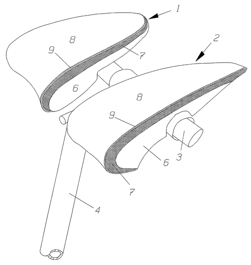
Fig. 1 is a perspective view of the bicycle seat seen from
above from the front.
Fig. 2 is a perspective view of the bicycle seat seen from be-
low from behind.


CA 02557715 2006-08-28
WO 2005/085051 PCT/SE2005/000303
2
With reference to fig. 1 it is seen that the bicycle seat con-
sists of two support portions 1 and 2, which are arranged on a
transversal mounting bar 3, which on its part is supported by
a pool 4, which forms a part of the bicycle frame. The two
support portions 1 and 2 can be displaced sideways on the bar
3 in relation to each other by being mounted each on a sepa-
rate socket, which is slidable and rotatable on the bar and
can be fastened by a handle 5. That means that the inclination
of the support portions in relation to the horizontal plane
l0 can be adjusted and fixed by the handle 5. The two support
portions 1 and 2 shall be fixed in relation to the bar 3 when
the bicycle seat is used meaning that the two support portions
shall not be able to tip or being displaced sideways. The bar
3 can be mounted to the pool 4 in different ways known per se
and does therefore not form a part of the invention.
It can further be seen from fig. 1 that the surface form of
the support portions is such that they are wider at the for-
ward edge than at the back edge. Further, it can be seen that
the forward edge is round in order to give good comfort.
The advantage of the invention is now that each one of the
support portions will meet and follow the movement of the seat
bone without tipping or moving in some other way. Each of the
support portions is therefore designed according to the fol-
lowing. The support portions consist mainly of three super im-
posed layers. The undermost one of the layers is a bottom
plate 6, which can be fixed non turnable on the mounting bar
3, that is to say the bottom plate can not tip forward or
backwards when fixed. The bottom plate 6 is suitably made from
stiff sheet-metal. A second layer in the form of a cushion 7
is fastened to the bottom plate 6, the cushion being elastic
in all directions. The elasticity of the cushion 7 shall be


CA 02557715 2006-08-28
WO 2005/085051 PCT/SE2005/000303
3
such that it is never totally compressed when being loaded by
the rider but shall follow the movement of the rider's seat
bone, which movement thus is as well known downwards and some-
what sideways, which taken together obliquely downwards and
sideways. This movement is largest at the forward end of the
support portion. The thickness of the cushion in this area is
previously about 10 cm and the hardness is between 5-70 Shore
A. As can be seen from fig. 1 the thickness of the cushion is
decreasing in the backward direction.
A third layer 8 is laid upon the cushion, which layer 8 is
stiff in all directions in its plane. However, it should be
observed that fig. 1 and 2 show an intermediate layer 9 in the
form of foamed plastic but this layer is not necessary in or-
der to achieve the desirable effect but is something which may
improve the comfort. It should be noted that the three layers,
the bottom plate 6, the cushion 7 and the upper layer 8 are
united with each other via meeting surfaces by using some sort
of adhesive means. The layers should not be able to slide in
relation to each other.
Within the scope of the invention there are other embodiments
than the above described and this concerns specifically the
bottom plate and the upper layer 8. The bottom layer shall be
stiff and thus suitably formed from metal. The uppermost layer
8 can be of woven fabric, leather or even thin metal plate.
The elasticity of the cushion can be varied according to the
rider's weight but should be so dimensioned that it can stand
the weight of the person without being completely compressed
when the rider pedals the bicycle.
Representative Drawing
A single figure which represents the drawing illustrating the invention.
Administrative Status

For a clearer understanding of the status of the application/patent presented on this page, the site Disclaimer , as well as the definitions for Patent , Administrative Status , Maintenance Fee  and Payment History  should be consulted.

Administrative Status

Title Date
Forecasted Issue Date Unavailable
(86) PCT Filing Date 2005-03-02
(87) PCT Publication Date 2005-09-15
(85) National Entry 2006-08-28
Dead Application 2009-03-02

Abandonment History

Abandonment Date Reason Reinstatement Date
2008-03-03 FAILURE TO PAY APPLICATION MAINTENANCE FEE

Payment History

Fee Type Anniversary Year Due Date Amount Paid Paid Date
Application Fee $400.00 2006-08-28
Maintenance Fee - Application - New Act 2 2007-03-02 $100.00 2007-02-19
Owners on Record

Note: Records showing the ownership history in alphabetical order.

Current Owners on Record
JANSCH, MIKAEL
Past Owners on Record
None
Past Owners that do not appear in the "Owners on Record" listing will appear in other documentation within the application.
Documents

To view selected files, please enter reCAPTCHA code :


To view images, click a link in the Document Description column. To download the documents, select one or more checkboxes in the first column and then click the "Download Selected in PDF format (Zip Archive)" or the "Download Selected as Single PDF" button.

List of published and non-published patent-specific documents on the CPD .

If you have any difficulty accessing content, you can call the Client Service Centre at 1-866-997-1936 or send them an e-mail at CIPO Client Service Centre.


Document
Description 
Date
(yyyy-mm-dd) 
Number of pages   Size of Image (KB) 
Abstract 2006-08-28 1 71
Claims 2006-08-28 2 57
Drawings 2006-08-28 2 52
Description 2006-08-28 3 132
Representative Drawing 2006-08-28 1 23
Cover Page 2006-10-26 1 50
PCT 2006-08-28 2 80
Assignment 2006-08-28 2 79