Note: Descriptions are shown in the official language in which they were submitted.
CA 02557754 2010-11-17
1
AN APPARATUS FOR THE EVAPORATIVE COOLING OF A LIQUID
PRODUCT
TECHNICAL FIELD
The present invention relates to an apparatus for the evaporative cooling of a
liquid product.
BACKGROUND ART
Heat treatment of liquid food products, such as milk, is a commonly
occurring industrial process today. By heating the product, extended shelf-
life will be
obtained by the extermination of those microorganisms which are to be found in
the
product. In the sterilisation of the food product, it is heated to
temperatures
exceeding 100 C. In order rapidly to heat to such elevated temperatures, steam
is
employed. The heating may take place either directly or indirectly. In
indirect
heating, use is made of different types of heat exchangers. In direct heating,
steam is
added directly to the product.
There are two types of direct heating of a liquid product, injection and
infusion. In injection, steam is injected into the product in a closed system.
Infusion
implies that the product is finely divided and caused to pass through a space
filled
with steam. In both cases, the supplied steam rapidly and efficiently heats up
the
product to the desired temperature and the product is then kept at this
temperature
during a given predetermined interval of time. The supplied steam must
thereafter be
removed from the product in order to avoid diluting it. This normally takes
place by
evaporative cooling, so-called flashcooling, in a vacuum chamber. During the
process, the steam is released and condensed at the same time as the product
is
cooled down to the temperature it had before the heat treatment.
CA 02557754 2006-08-29
WO 2005/084451 PCT/SE2005/000324
2
The evaporative cooling usually takes place in that the steamed product is
fed, under pressure, into a vacuum chamber. When the product enters into the
vacuum chamber, the liquid boils, the steam is released and rises upwards in
the
chamber while the product accumulates in the lower region of the chamber. Thus
cooled, the product may be tapped off from the lower region of the chamber.
The
steam which leaves the product together with incondensable gases is to be
condensed
in order for it to be able to be run off to an outlet. The condensation may be
put into
effect either in that the steam and the gases are led into a further vacuum
chamber
where the steam is cooled by being showered with cold water, or that the steam
is
condensed in some form of water-cooled plate condenser or tube condenser. The
plate or tube condenser may be integrated in the first vacuum chamber or
alternatively be placed outside it.
The majority of the apparatuses in existence today for condensing the steam
are relatively expensive to manufacture since, in the first case, an extra
vacuum
chamber is required, or alternatively some form of condenser is needed. For
the
conventional method of condensing the steam, a considerable quantity of
coolant
water is moreover consumed, and this water should be of good quality so as to
avoid
limestone furring and corrosion on plates or tubes in the condenser.
Swedish Patent Specification SE 514 560 discloses an apparatus for
evaporative cooling which only utilises one vacuum chamber. The vacuum chamber
is divided into two concentrically placed spaces which are open upwards
towards the
upper end wall of the chamber. The steamed product enters into the one space,
and in
the second space the released steam is showered with coolant water from a
closed
circulation circuit. Nor does this apparatus require any expensive and
complicated
condensers. However, one drawback inherent in this apparatus is that there is
a risk
that the coolant water which is employed for condensing the steam may splash
over
to the second space and thereby dilute the product, or even worse run the risk
of
infecting the sterile food product. By showering with coolant liquid from
above in
the one space, there is also created a cold surface against the product space
which
may result in the steam in the product being condensed too early and that a
part of
the steam thereby accompanies the product out from the plant.
CA 02557754 2010-11-17
3
SUMMARY OF THE INVENTION
One object of the present invention is to design the apparatus intimated by
way of
introduction so that the coolant water which is showered over the released
steam does not
run the risk of finding its way into the product.
A further object of the present invention is to design the apparatus so that
there is
no cold surface against the product which results in the steam in the product
being
condensed too early and thereby accompanying the product.
Yet a further object of the present invention is that the closed coolant water
circuit
may be washed together with the remaining processing equipment which is
sterilised
together with other equipment, thus affording increased safety and reliability
for an
apparatus which handles sensitive food products.
These and other objects have been attained according to the present invention
in
that the apparatus of the type described by way of introduction has been given
the
characterising feature that the first space is extended downwards so that it
extends at least
as far below the bottom of the vacuum chamber as the extent of the space
inside the
vacuum chamber.
According to an aspect of the present invention there is provided an apparatus
for
evaporative cooling of a liquid product, the apparatus comprising:
a vacuum chamber including a top wall and a bottom wall, the vacuum chamber
being divided into a first chamber centrally positioned with respect to a
longitudinal axis
of the vacuum chamber and a second chamber which concentrically surrounds the
first
chamber and in which both the first and second chambers are open towards the
top wall
of the vacuum chamber, and the first chamber has an outlet for condensed steam
and the
second chamber has an inlet for steamed product and an outlet for the product;
a circulation circuit for coolant liquid, wherein the first chamber has an
upper part
located inside the vacuum chamber and a lower part located beneath the bottom
wall of
the vacuum chamber, and the lower part extends downwards below the bottom wall
of
the vacuum chamber so that a length of the lower part below the bottom wall is
at least
the same as a length of the upper part inside the vacuum chamber; and
a coolant conduit positioned inside the lower part of the first chamber
located
below the bottom wall for delivering coolant to cool the condensed steam.
CA 02557754 2010-11-17
3a
According to another aspect of the present invention there is provided the
apparatus as described herein, wherein the upper part of the first chamber
located inside
the vacuum chamber and the lower part of the first chamber located beneath the
bottom
wall of the vacuum chamber are configured to be detachable from each other.
According to a further aspect of the present invention there is provided the
apparatus as described herein, wherein the inlet for the steamed product is
tangentially
disposed in a side wall of the vacuum chamber, and wherein the inlet is formed
as a
vertical gap.
According to another aspect of the present invention there is provided the
apparatus as described herein, wherein the circulation circuit for the coolant
liquid
discharges via the coolant conduit in an upper region of a lower part of the
first chamber.
According to a further aspect of the present invention there is provided the
apparatus as described herein, wherein the outlet for the condensed steam is a
spillway
overflow.
According to a further aspect of the present invention there is provided the
apparatus as described herein, wherein a number of downwardly directed
apertures are
provided in an upper region of the coolant conduit.
According to a further aspect of the present invention there is provided the
apparatus as described herein, wherein the circulation circuit for the coolant
liquid
includes an outlet, conduits, a centrifugal pump, and a cooler.
According to a further aspect of the present invention there is provided the
apparatus as described herein, wherein ingress and egress of the coolant
liquid is at a
lower portion of the lower part of the first chamber.
BRIEF DESCRIPTION OF THE ACCOMPANYING DRAWINGS
One preferred embodiment of the present invention will now be described in
greater detail hereinbelow, with reference to the accompanying Drawings. In
the
accompanying Drawings:
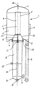
Fig. I is a side elevation, partly in section, of the vacuum chamber in the
apparatus; and
Fig. 2 is a flow diagram for the apparatus.
CA 02557754 2010-11-17
3b
DESCRIPTION OF PREFERRED EMBODIMENT
The present invention relates to an apparatus for the evaporative cooling of a
liquid product comprising a vacuum chamber divided into a first centrally
positioned
space and a second space which concentrically surrounds the first space and
where both
of the spaces are open towards the upper end wall of the vacuum chamber, the
first space
having an outlet for condensed steam and the second space having an inlet for
steamed
product, as well as an outlet for the product, the apparatus further including
a circulation
circuit for coolant liquid.
An apparatus for the evaporative cooling of a liquid product comprises a
vacuum
chamber 1 which is shown in detail in Fig. 1. The vacuum chamber 1 has an
CA 02557754 2006-08-29
WO 2005/084451 PCT/SE2005/000324
4
upper end wall 2, a side wall 3 and a bottom wall 4. Inside the vacuum chamber
1,
there is disposed an additional circular wall 5 which divides the vacuum
chamber 1
into two concentrically disposed spaces, a first space 6 and a second space 7.
Both of
the spaces 6, 7 are open towards the upper end wall 2 of the vacuum chamber 1.
The
lower definition of the second space 7 consists of the bottom wall 4 of the
vacuum
chamber 1.
The first space 6 which is positioned centrally in the vacuum chamber 1 is
extended downwards so that the space 6 continues below the bottom wall 4 of
the
vacuum chamber 1, so that the space 6 consists of two parts 8, 9. That part 8
of the
space 6 which is located below the bottom wall 4 is of a longer or
alternatively
equally long extent as that part 9 which is located above the bottom wall 4
and inside
the vacuum chamber 1. The lower part 8 has a bottom portion 10 which is
rounded-
off or otherwise suitably designed for a vacuum chamber.
As a result of the above-described design of the vacuum chamber with both
of its spaces 6, 7, no manhole is required on the vacuum chamber 1. By
disconnecting the lower part 8 of the first space 6 from the upper part 9 at a
connection 29, it is then possible to draw out the upper part 9 from the
vacuum
chamber 1 and by such means gain access to the vacuum chamber 1. In that the
manhole becomes superfluous, the vacuum chamber 1 may be manufactured
considerably more economically.
In the second space 7 in the vacuum chamber 1, there is provided an inlet 11
for the steamed, heated product. The inlet 11 is tangentially disposed in the
side wall
2 of the vacuum chamber 1 and is arranged as a vertical gap. In the second
space 7,
there is also provided an outlet 12 for the cooled product. The bottom wall 4
of the
vacuum chamber 1 is designed so that liquid, i.e. product or cleaning liquid,
cannot
be left standing in the lower region of the second space 7. The outlet 12 is
connected
to a conduit 13 which, via a centrifugal pump 14, pumps the product further
for
continued treatment.
The first space 6 has, in its bottom portion 10, an outlet 15 for the coolant
liquid, preferably water, which is to condense the steam from the product. The
outlet
15 is connected to a conduit 16 which, via a centrifugal pump 17, pumps the
coolant
CA 02557754 2006-08-29
WO 2005/084451 PCT/SE2005/000324
water to a cooler 30. The cooler 30 may, for example, be a plate heat
exchanger. The
cooler 30 is also connected to a cold water conduit 18.
From the cooler 30, the coolant water passes further into an almost closed
circuit via a conduit 28, back to a coolant water inlet 19 in the bottom
portion 10 of
5 the first space 6. The coolant water conduit continues through most of the
lower part
8 of the first space 6. That portion 20 which passes through the lower part 8
of the
first space 6 has, in its upper end, a number of apertures 21 which are
directed
downwards. Through these apertures 21, coolant water is showered down onto the
steam which is located in the lower part 8 of the first space 6. The number of
apertures 21 depends upon the capacity for which the apparatus is calculated.
The coolant water conduit 20 passing through the part 8 may also be extended
somewhat upwards so that there will be provided a short pipe length 22 of
slight
diameter which, in its upper region, is provided with a number of holes 23.
These
holes 23 may, if necessary, be employed for cooling the wall surface 24
between the
first 6 and the second 7 space. For products which show a ready tendency to
froth,
the cooling of the wall surface 24 may contribute in counteracting the
frothing. A
large frothing may entail that product froth may accompany the steam into the
first
space 6, with product losses as a result.
In the lower part 8 of the first space 6, there is also provided an outlet 25
for
the condensed steam and the incondensable gases departing from the product.
The
outlet 25 is designed as a spillway overflow. The conduit from this outlet 25
normally passes via a vacuum pump 31 to an outlet. It is this vacuum pump 31
which
besides creates vacuum in the chamber 1.
The vacuum chamber 1 is also provided with one or more connections 26 for
cleaning, with spray nozzles 27 placed inside the upper region of the vacuum
chamber 1. By interconnecting the closed coolant water circuit by valve
arrangement
with the remaining processing equipment, the coolant water circuit may be
washed
together with the remaining equipment and be connected to the standard CIP
equipment (Cleaning In Place) with which conventional processing plants are
equipped. As a result of these valve arrangements, the closed coolant water
circuit
may also be sterilised together with remaining processing equipment, which
affords
an additional level of safety if coolant water were to leak into the product.
CA 02557754 2006-08-29
WO 2005/084451 PCT/SE2005/000324
6
The product, which is normally at a temperature of 70 to 120 C, is heat
treated before entering the apparatus. The product is heated by being directly
supplied with steam in an injector or an infuser (not shown). The product is
heated in
the injector or infuser normally to a temperature of from 100 to 150 C and is
then
kept at this temperature in a holding cell (not shown) for a given
predetermined
interval of time. This interval of time is dependant upon the treatment
temperature.
After the holding cell, the product which is mixed with steam enters under
pressure into the vacuum chamber 1 of the apparatus through the tangential
inlet 11.
As a result of the tangential design of the inlet 11, the product will follow
the side
wall 3 in the chamber 1 as a result of so-called cyclone effect. When the
product
enters into the vacuum chamber 1 under pressure, the liquid will boil on the
sudden
pressure drop, in which event steam and incondensable gases are released from
the
product. The heavier product falls downwards in the second space 7, while the
lighter
steam and the incondensable gases rise.
The product which has been freed of steam is now at a temperature
corresponding to the temperature it had before the heat treatment, i.e.
between 70 and
120 C. The product is accumulated in the lower portion of the second space 7
in the
vacuum chamber 1 and departs therefrom through the outlet 12. Via the conduit
13
and the centrifugal pump 14, the product is transported further to additional
cooling,
or alternatively to other treatment.
The steam and the incondensable gases that have risen upwards in the
vacuum chamber 1 are drawn down in the upper portion 9 of the first space 6
which
functions as an evacuation pipe. In the lower part 8 of the first space 6, the
steam and
gases will be showered with coolant water from the coolant water conduit 20
and the
apertures 21. The coolant water may be at a temperature of between 10 and 40
C.
The higher the temperature of the coolant water, the greater will be the
quantity of
coolant water which is consumed for condensing the steam. In that the coolant
water
is showered out over the steam at a level which lies below the upper part 8 of
the first
space 6, there is no risk that coolant water, which may be unsterile, leaks
into the
product.
CA 02557754 2006-08-29
WO 2005/084451 PCT/SE2005/000324
7
The condensed steam, the coolant water and the incondensable gases
accumulate in the lower region of the lower part 8 of the first space 6. The
spillway
overflow 25 is disposed here such that the addition of condensed steam and
gases
leaves the apparatus through this spillway overflow 25, whereafter the
condensed
steam and the gases are normally led direct to an outlet.
The coolant water which accumulates under the spillway overflow 25 in the
lower region of the lower part 8 of the first space 6 is included in the
almost closed
circulation circuit for coolant water which is included in the apparatus. Via
the outlet
and the conduit 16, coolant water is pumped from the vacuum chamber 1 by
10 means of the circulation pump 17 to the cooler 30. The cooler 30 may, for
example,
consist of a plate heat exchanger. In the cooler 30, the water is cooled to a
temperature of between 10 and 40 C with the aid of cold water which enters
into the
cooler 30 through the conduit 18.
After the cooler 30, the coolant water passes back to the vacuum chamber 1
15 via the conduit 28, through the inlet 19 and the conduit 20 where the
coolant water is
once again utilised for showering the released steam from the product. By
employing
an almost closed coolant water circuit, the consumption of coolant liquid is
reduced.
By a suitable valve arrangement, the coolant water circuit is washable and is
capable
of being sterilised together with the rest of the process equipment.
As will have been apparent from the foregoing description, the present
invention realises an apparatus for the evaporative cooling of a liquid food
product
which is cheaper than most apparatuses occurring on the market. The apparatus
ensures that the coolant water cannot reach the product at any stage. In that
the
coolant water circuit may be washed and sterilised with the rest of the
equipment, an
even more hygienic apparatus will be obtained. As a result of the design of
the
apparatus, there will be no cold surface against that space where the product
is kept,
with the result that the steam in the product is not condensed too early and
thereby
accompanies the product.