Language selection

Search

Patent 2557756 Summary

Third-party information liability

Some of the information on this Web page has been provided by external sources. The Government of Canada is not responsible for the accuracy, reliability or currency of the information supplied by external sources. Users wishing to rely upon this information should consult directly with the source of the information. Content provided by external sources is not subject to official languages, privacy and accessibility requirements.

Claims and Abstract availability

Any discrepancies in the text and image of the Claims and Abstract are due to differing posting times. Text of the Claims and Abstract are posted:

  • At the time the application is open to public inspection;
  • At the time of issue of the patent (grant).
(12) Patent Application: (11) CA 2557756
(54) English Title: HYDRAULIC CYLINDER
(54) French Title: VERIN HYDRAULIQUE
Status: Deemed Abandoned and Beyond the Period of Reinstatement - Pending Response to Notice of Disregarded Communication
Bibliographic Data
Abstracts

English Abstract


A hydraulic cylinder comprises a piston, which is movable inside a tube
between an end cup and a head gland
in the direction of the cylinder axis. The head gland is provided with an
opening for a piston rod, and a clevis is
attached to the end cup. Each tube end is provided with the internal screw
thread, which is adapted for cooperation
with the external screw thread at each of the end cup and the head gland. A
spacer can be added to rearrange the
rotational position of the clevis with respect to the oil ports. The end cup
can be provided with an optional
cushion unit, and metering passages can be built in this end cup.


Claims

Note: Claims are shown in the official language in which they were submitted.

CLAIM
1.The hydraulic cylinder shown in the FIG.1 and FIG.2 comprises a cylindrical
tube 4 with a head gland 2 and an
end cup 9. The head gland 2 is provided with an opening for a piston rod 1
which is connected to a piston 11, and
the piston 11 has a free linear movement inside the tube 4 between the head
gland 2 and the end cup 9. The
diameter of the bore in the head gland 2 is larger than the diameter of the
piston rod 1. The head gland 2 and the
end cup 9 are connected to the tube 4 via screw joints, each tube end is
provided with the internal screw thread,
which is adapted for cooperation with the external screw thread at each of the
head gland 2 and the end cup 9.
2. The hydraulic cylinder of Claim 1, wherein the said head gland 2 and the
end cup 9 shown in FIG.1 are
provided with groove for O-ring and backup ring 3, 8 to prevent from leaking,
and the head gland 2 also is
provided with shaft seals 13. The piston 11 locked on rod 1 by set screw 7, is
provided with piston seals 6 and
O-ring 5.
3. The hydraulic cylinder of Claim 1, wherein the said tube 4 is designed with
two ports B, C shown in FIG.1,
which are to be connected with hydraulic fittings.

Page 4
4. The hydraulic cylinder of Claim 1, wherein the piston rod 1 is provided
with a plunger A as shown in FIG.1,
which diameter is smaller than that of the bore H shown in FIG.4.
5. The hydraulic cylinder of Claim 1, wherein the said end cup 9 shown in
FIG.4 may be provided with optional
cushion passages D, E, F, G, H.
6.The hydraulic cylinder of Claim 1, wherein the said end cup 9 can be
provided with a cushion unit comprising
an adjustable spool 19, O-ring (with backup ring) 18, a lock nut 17, and
passages F, G, which are shown in FIG.3-
FIG.6. Shown in FIG.4, a check valve unit which includes a NPT plug14, a ball
15, a spring 16, and passages
D, E, is also comprised in the said end cup 9.
7.The hydraulic cylinder of Claim 6, wherein the said adjustable spool 19 is
locked by lock nut 17.As the piston
11 with plunger A extends toward the bore H in the end cup 9, the flow of
exhausted fluid will be restricted
through the passages F, G. The metering adjustment of exhausted fluid through
the passage F also can be
accomplished by turning the adjustable spool 19.
8. The hydraulic cylinder of Claim 6, wherein the said ball 15 and spring 16
are held by an NPT plug 14, which
keep the flow of fluid in one direction. When piston 11 is extended and the
plunger A is still moving inside the
bore H, this check valve unit will be open.
9. The hydraulic cylinder of Claim 6, wherein the said cushion adjustment unit
A, D, E, F, G, H and 14-19 may
be eliminated, and it becomes a threaded end cup cylinder without cushion.
10.A method of manufacturing this cylinder of claim 1, the end cup 9 and the
tube 4 will be preassembled in
locking engagement. Then the desired position of ports B, C will be located.
Drilling and taping could be
accomplished only after the component comprising the end cup 9 and the tube 4
has been disassembled. In this
case, The spacer 10 will not be needed.

Page 5
11. The method of claim 10, wherein the said spacer 10 may be needed when
different orientation of the end cup
9 with respect to the oil port B, C is required. The thickness of the spacer
10 can be calculated according to the
pitch of the thread on the end cup 9 and the rotating angle required. After
the said spacer 10 is located between
the end cup 9 and the tube 4 in locking engagement, the end cup 9 will be
rearranged on the tube 4 in some
desired turning position about the cylinder axis with respect to the oil
ports.
12. The hydraulic cylinder of Claim 1,wherein the invention is not limited to
the above described embodiment,
but several variants are conceivable within the scope of the accompanying
claims. For example, the style of the
clevis J of the said cylinder may be different.

Description

Note: Descriptions are shown in the official language in which they were submitted.


CA 02557756 2006-08-16
Pagelof 5
DETAILED DESCRIPTION OF THE INVENTION
This invention relates to a hydraulic cylinder with a special end cup. A
welded cylinder or a tie rod cylinder is very
common in the industrial application. When a welded hydraulic cylinder is
applied in the engineering, the
following disadvantages must be considered, such as extra welding process,
thermal deformation of the tube, and
the cushion unit being difficult to be made etc. In the same time, there is a
lot of limitation when a tie rod cylinder
is used as a component of machines, such as taking more space and too heavy.
When designed a welded hydraulic cylinder, I found the welded end cup can be
replaced by a standard end cup
with the external thread. Although there are many kinds of modification on the
welded end cup, more parts will
be needed to replace this welded end cup and the manufacturing process will be
more complicated.
In this invention of this hydraulic cylinder, only one end cup with a clevis
is needed to replace a traditional
welded end cup, and can be designed as a standard part to facilitate the
manufacture of the hydraulic cylinder. For
this kind of hydraulic cylinder, a cushion unit including cushion passages can
be comprised in the end cup just
like the tie rod cylinder. Inlet or outlet ports are located at the tube, and
the tube can be designed as a standard
part according to strokes, piston size, tube thickness. This cylinder can be
also designed as a heavy duty hydraulic
cylinder and applied in the different working condition.
This end cup is connected with the tube via screw joints, and the clevis is
attached to the end cup, so the orientation
of the inlet/outlet ports which attach the tube of the cylinder can be
adjusted with respect to the clevis only adding
spacers between the end cup and tube. Therefore, limitations on the mounting
position of the cylinder can be
avoided in the future service.
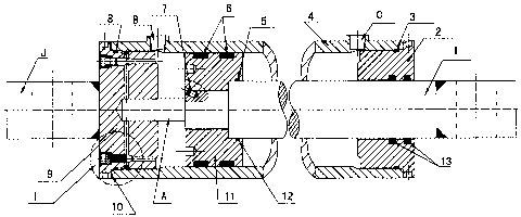
In drawings which illustrate embodiments of the invention, FIG.1 shows a
longitudinal section through a cylinder
according to the invention; FIG.2 is top view of this cylinder; FIG.3 is
sectional view of I and II in somewhat
enlarged scale, which are from FIG.1 and FIG.2; FIG.4 is a detailed drawing of
the end cup according to the
invention; FIG.5 is detail drawing of the adjustable spool from the cushion
unit; FIG.6 is a detailed drawing of

CA 02557756 2006-08-16
Page 2 of 5
the lock nut from the cushion unit.
The hydraulic cylinder shown in the FIG.1 comprises a cylindrical tube 4 with
a head gland 2 and an end cup 9.
The head gland 2 is provided with an opening for a piston rod 1 which is
connected to a piston 11, which has a
free linear movement between the head gland 2 and the end cup 9 inside the
tube 4.
Shown in FIG. 1, the diameter of the bore in the head gland 2 is larger than
the diameter of the piston rod 1. The
end cup 9 and the head gland 2 are connected to the tube 4 via screw joints,
each tube end is provided with
internal screw thread, which is adapted for cooperation with external screw
thread at each of the end cup 9 and
the head gland 2. The end cup 9 may be provided with optional cushion passages
and a clevis J, which is shown
in FIG.4.
The head gland 2 and the end cup 9 are provided with grooves for 0-ring and
backup ring 3, 8 to prevent from
leaking. The head gland 2 also is provided with shaft seals 13, and the piston
11 is provided with piston seals
6 and 0-ring 5. The piston 11 is locked on the rod I by a set screw 7. There
are two ports B, C, which are to be
connected with hydraulic fittings.
When this cylinder is assembled, in the first the end cup 9 and the tube 4
have to be preassembled in locking
engagement. Then the desired position of ports B, C will be located. Drilling
and taping the two ports (B, C) can
be accomplished only after disassemble the component (comprising the end cup 9
and the tube 4). In this case,
no spacer is needed.
When the different orientation of the end cup No.9 with respect to the oil
ports (B, C )is required in the future
service, the spacer 10 will be needed on this condition. After the spacer 10
is assembled with the end cup 9 and
the tube 4 in locking engagement, the end cup 9 will be rearranged on the tube
4 in some desired rotational
position about the cylinder axis with respect to the clevis J and the oil
ports B, C. The thickness of the spacer 10
can be calculated according to the pitch of the thread on the end cup 9 and
the rotating angle required.

CA 02557756 2006-08-16
Page 3 of 5
Shown in FIG.3 and FIG.4, a cusllion unit may be provided with metering
passages F, G in the end cup 9 of the
cylinder through which exhausted fluid is expelled. As the piston l l with the
plunger A (shown in F1G.1) extends
toward the bore H in the end cup 9, the flow of exhausted fluid will be
restricted. Adjustment of inetering
exhausted fluid through H will be acconiplished by turning an adjustable spool
19 shown in FIG.5, which is
locked by a lock nut 17 shown in FIG.6. The second series of passages( D, E)
comprising a check valve unit( a
ball 15, and a spring 16), keep the flow of fluid in one direction. This
cushion adjustment unit A, D, E, F, G, H,
and item 14-19 (shown in FIG.I-5) may be eliminated, and this cylinder becomes
a threaded end cup cylinder
without cushion.
The invention is not limited to the above described embodiment, but several
variants are conceivable within the
scope of the accompanying claims. For example, the style of the clevis J may
be different.

Representative Drawing
A single figure which represents the drawing illustrating the invention.
Administrative Status

2024-08-01:As part of the Next Generation Patents (NGP) transition, the Canadian Patents Database (CPD) now contains a more detailed Event History, which replicates the Event Log of our new back-office solution.

Please note that "Inactive:" events refers to events no longer in use in our new back-office solution.

For a clearer understanding of the status of the application/patent presented on this page, the site Disclaimer , as well as the definitions for Patent , Event History , Maintenance Fee  and Payment History  should be consulted.

Event History

Description Date
Application Not Reinstated by Deadline 2010-08-16
Time Limit for Reversal Expired 2010-08-16
Inactive: Adhoc Request Documented 2010-07-22
Inactive: Adhoc Request Documented 2010-05-19
Deemed Abandoned - Failure to Respond to Maintenance Fee Notice 2009-08-17
Application Published (Open to Public Inspection) 2008-02-16
Inactive: Cover page published 2008-02-15
Inactive: First IPC assigned 2007-01-10
Inactive: IPC assigned 2007-01-10
Inactive: Office letter 2006-10-03
Filing Requirements Determined Compliant 2006-09-26
Inactive: Filing certificate - No RFE (English) 2006-09-26
Application Received - Regular National 2006-09-26
Small Entity Declaration Determined Compliant 2006-08-16

Abandonment History

Abandonment Date Reason Reinstatement Date
2009-08-17

Maintenance Fee

The last payment was received on 2008-08-15

Note : If the full payment has not been received on or before the date indicated, a further fee may be required which may be one of the following

  • the reinstatement fee;
  • the late payment fee; or
  • additional fee to reverse deemed expiry.

Please refer to the CIPO Patent Fees web page to see all current fee amounts.

Fee History

Fee Type Anniversary Year Due Date Paid Date
Application fee - small 2006-08-16
MF (application, 2nd anniv.) - small 02 2008-08-18 2008-08-15
Owners on Record

Note: Records showing the ownership history in alphabetical order.

Current Owners on Record
MINGZE WANG
Past Owners on Record
None
Past Owners that do not appear in the "Owners on Record" listing will appear in other documentation within the application.
Documents

To view selected files, please enter reCAPTCHA code :


To view images, click a link in the Document Description column. To download the documents, select one or more checkboxes in the first column and then click the "Download Selected in PDF format (Zip Archive)" or the "Download Selected as Single PDF" button.

List of published and non-published patent-specific documents on the CPD .

If you have any difficulty accessing content, you can call the Client Service Centre at 1-866-997-1936 or send them an e-mail at CIPO Client Service Centre.


Document
Description 
Date
(yyyy-mm-dd) 
Number of pages   Size of Image (KB) 
Abstract 2006-08-16 1 14
Description 2006-08-16 3 110
Claims 2006-08-16 3 79
Drawings 2006-08-16 6 79
Representative drawing 2007-08-09 1 15
Cover Page 2008-02-05 1 41
Filing Certificate (English) 2006-09-26 1 158
Notice: Maintenance Fee Reminder 2008-05-20 1 129
Notice: Maintenance Fee Reminder 2009-05-20 1 119
Courtesy - Abandonment Letter (Maintenance Fee) 2009-10-13 1 171
Second Notice: Maintenance Fee Reminder 2010-02-17 1 119
Notice: Maintenance Fee Reminder 2010-05-18 1 132
Correspondence 2006-09-26 1 9
Fees 2008-08-15 1 47
Correspondence 2010-02-17 3 390
Correspondence 2010-07-29 3 182