Sélection de la langue

Search

Sommaire du brevet 2557756 

Énoncé de désistement de responsabilité concernant l'information provenant de tiers

Une partie des informations de ce site Web a été fournie par des sources externes. Le gouvernement du Canada n'assume aucune responsabilité concernant la précision, l'actualité ou la fiabilité des informations fournies par les sources externes. Les utilisateurs qui désirent employer cette information devraient consulter directement la source des informations. Le contenu fourni par les sources externes n'est pas assujetti aux exigences sur les langues officielles, la protection des renseignements personnels et l'accessibilité.

Disponibilité de l'Abrégé et des Revendications

L'apparition de différences dans le texte et l'image des Revendications et de l'Abrégé dépend du moment auquel le document est publié. Les textes des Revendications et de l'Abrégé sont affichés :

  • lorsque la demande peut être examinée par le public;
  • lorsque le brevet est émis (délivrance).
(12) Demande de brevet: (11) CA 2557756
(54) Titre français: VERIN HYDRAULIQUE
(54) Titre anglais: HYDRAULIC CYLINDER
Statut: Réputée abandonnée et au-delà du délai pour le rétablissement - en attente de la réponse à l’avis de communication rejetée
Données bibliographiques
Abrégés

Abrégé anglais


A hydraulic cylinder comprises a piston, which is movable inside a tube
between an end cup and a head gland
in the direction of the cylinder axis. The head gland is provided with an
opening for a piston rod, and a clevis is
attached to the end cup. Each tube end is provided with the internal screw
thread, which is adapted for cooperation
with the external screw thread at each of the end cup and the head gland. A
spacer can be added to rearrange the
rotational position of the clevis with respect to the oil ports. The end cup
can be provided with an optional
cushion unit, and metering passages can be built in this end cup.

Revendications

Note : Les revendications sont présentées dans la langue officielle dans laquelle elles ont été soumises.


CLAIM
1.The hydraulic cylinder shown in the FIG.1 and FIG.2 comprises a cylindrical
tube 4 with a head gland 2 and an
end cup 9. The head gland 2 is provided with an opening for a piston rod 1
which is connected to a piston 11, and
the piston 11 has a free linear movement inside the tube 4 between the head
gland 2 and the end cup 9. The
diameter of the bore in the head gland 2 is larger than the diameter of the
piston rod 1. The head gland 2 and the
end cup 9 are connected to the tube 4 via screw joints, each tube end is
provided with the internal screw thread,
which is adapted for cooperation with the external screw thread at each of the
head gland 2 and the end cup 9.
2. The hydraulic cylinder of Claim 1, wherein the said head gland 2 and the
end cup 9 shown in FIG.1 are
provided with groove for O-ring and backup ring 3, 8 to prevent from leaking,
and the head gland 2 also is
provided with shaft seals 13. The piston 11 locked on rod 1 by set screw 7, is
provided with piston seals 6 and
O-ring 5.
3. The hydraulic cylinder of Claim 1, wherein the said tube 4 is designed with
two ports B, C shown in FIG.1,
which are to be connected with hydraulic fittings.

Page 4
4. The hydraulic cylinder of Claim 1, wherein the piston rod 1 is provided
with a plunger A as shown in FIG.1,
which diameter is smaller than that of the bore H shown in FIG.4.
5. The hydraulic cylinder of Claim 1, wherein the said end cup 9 shown in
FIG.4 may be provided with optional
cushion passages D, E, F, G, H.
6.The hydraulic cylinder of Claim 1, wherein the said end cup 9 can be
provided with a cushion unit comprising
an adjustable spool 19, O-ring (with backup ring) 18, a lock nut 17, and
passages F, G, which are shown in FIG.3-
FIG.6. Shown in FIG.4, a check valve unit which includes a NPT plug14, a ball
15, a spring 16, and passages
D, E, is also comprised in the said end cup 9.
7.The hydraulic cylinder of Claim 6, wherein the said adjustable spool 19 is
locked by lock nut 17.As the piston
11 with plunger A extends toward the bore H in the end cup 9, the flow of
exhausted fluid will be restricted
through the passages F, G. The metering adjustment of exhausted fluid through
the passage F also can be
accomplished by turning the adjustable spool 19.
8. The hydraulic cylinder of Claim 6, wherein the said ball 15 and spring 16
are held by an NPT plug 14, which
keep the flow of fluid in one direction. When piston 11 is extended and the
plunger A is still moving inside the
bore H, this check valve unit will be open.
9. The hydraulic cylinder of Claim 6, wherein the said cushion adjustment unit
A, D, E, F, G, H and 14-19 may
be eliminated, and it becomes a threaded end cup cylinder without cushion.
10.A method of manufacturing this cylinder of claim 1, the end cup 9 and the
tube 4 will be preassembled in
locking engagement. Then the desired position of ports B, C will be located.
Drilling and taping could be
accomplished only after the component comprising the end cup 9 and the tube 4
has been disassembled. In this
case, The spacer 10 will not be needed.

Page 5
11. The method of claim 10, wherein the said spacer 10 may be needed when
different orientation of the end cup
9 with respect to the oil port B, C is required. The thickness of the spacer
10 can be calculated according to the
pitch of the thread on the end cup 9 and the rotating angle required. After
the said spacer 10 is located between
the end cup 9 and the tube 4 in locking engagement, the end cup 9 will be
rearranged on the tube 4 in some
desired turning position about the cylinder axis with respect to the oil
ports.
12. The hydraulic cylinder of Claim 1,wherein the invention is not limited to
the above described embodiment,
but several variants are conceivable within the scope of the accompanying
claims. For example, the style of the
clevis J of the said cylinder may be different.

Description

Note : Les descriptions sont présentées dans la langue officielle dans laquelle elles ont été soumises.

CA 02557756 2006-08-16
Pagelof 5
DETAILED DESCRIPTION OF THE INVENTION
This invention relates to a hydraulic cylinder with a special end cup. A
welded cylinder or a tie rod cylinder is very
common in the industrial application. When a welded hydraulic cylinder is
applied in the engineering, the
following disadvantages must be considered, such as extra welding process,
thermal deformation of the tube, and
the cushion unit being difficult to be made etc. In the same time, there is a
lot of limitation when a tie rod cylinder
is used as a component of machines, such as taking more space and too heavy.
When designed a welded hydraulic cylinder, I found the welded end cup can be
replaced by a standard end cup
with the external thread. Although there are many kinds of modification on the
welded end cup, more parts will
be needed to replace this welded end cup and the manufacturing process will be
more complicated.
In this invention of this hydraulic cylinder, only one end cup with a clevis
is needed to replace a traditional
welded end cup, and can be designed as a standard part to facilitate the
manufacture of the hydraulic cylinder. For
this kind of hydraulic cylinder, a cushion unit including cushion passages can
be comprised in the end cup just
like the tie rod cylinder. Inlet or outlet ports are located at the tube, and
the tube can be designed as a standard
part according to strokes, piston size, tube thickness. This cylinder can be
also designed as a heavy duty hydraulic
cylinder and applied in the different working condition.
This end cup is connected with the tube via screw joints, and the clevis is
attached to the end cup, so the orientation
of the inlet/outlet ports which attach the tube of the cylinder can be
adjusted with respect to the clevis only adding
spacers between the end cup and tube. Therefore, limitations on the mounting
position of the cylinder can be
avoided in the future service.
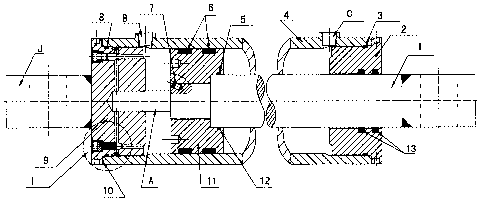
In drawings which illustrate embodiments of the invention, FIG.1 shows a
longitudinal section through a cylinder
according to the invention; FIG.2 is top view of this cylinder; FIG.3 is
sectional view of I and II in somewhat
enlarged scale, which are from FIG.1 and FIG.2; FIG.4 is a detailed drawing of
the end cup according to the
invention; FIG.5 is detail drawing of the adjustable spool from the cushion
unit; FIG.6 is a detailed drawing of

CA 02557756 2006-08-16
Page 2 of 5
the lock nut from the cushion unit.
The hydraulic cylinder shown in the FIG.1 comprises a cylindrical tube 4 with
a head gland 2 and an end cup 9.
The head gland 2 is provided with an opening for a piston rod 1 which is
connected to a piston 11, which has a
free linear movement between the head gland 2 and the end cup 9 inside the
tube 4.
Shown in FIG. 1, the diameter of the bore in the head gland 2 is larger than
the diameter of the piston rod 1. The
end cup 9 and the head gland 2 are connected to the tube 4 via screw joints,
each tube end is provided with
internal screw thread, which is adapted for cooperation with external screw
thread at each of the end cup 9 and
the head gland 2. The end cup 9 may be provided with optional cushion passages
and a clevis J, which is shown
in FIG.4.
The head gland 2 and the end cup 9 are provided with grooves for 0-ring and
backup ring 3, 8 to prevent from
leaking. The head gland 2 also is provided with shaft seals 13, and the piston
11 is provided with piston seals
6 and 0-ring 5. The piston 11 is locked on the rod I by a set screw 7. There
are two ports B, C, which are to be
connected with hydraulic fittings.
When this cylinder is assembled, in the first the end cup 9 and the tube 4
have to be preassembled in locking
engagement. Then the desired position of ports B, C will be located. Drilling
and taping the two ports (B, C) can
be accomplished only after disassemble the component (comprising the end cup 9
and the tube 4). In this case,
no spacer is needed.
When the different orientation of the end cup No.9 with respect to the oil
ports (B, C )is required in the future
service, the spacer 10 will be needed on this condition. After the spacer 10
is assembled with the end cup 9 and
the tube 4 in locking engagement, the end cup 9 will be rearranged on the tube
4 in some desired rotational
position about the cylinder axis with respect to the clevis J and the oil
ports B, C. The thickness of the spacer 10
can be calculated according to the pitch of the thread on the end cup 9 and
the rotating angle required.

CA 02557756 2006-08-16
Page 3 of 5
Shown in FIG.3 and FIG.4, a cusllion unit may be provided with metering
passages F, G in the end cup 9 of the
cylinder through which exhausted fluid is expelled. As the piston l l with the
plunger A (shown in F1G.1) extends
toward the bore H in the end cup 9, the flow of exhausted fluid will be
restricted. Adjustment of inetering
exhausted fluid through H will be acconiplished by turning an adjustable spool
19 shown in FIG.5, which is
locked by a lock nut 17 shown in FIG.6. The second series of passages( D, E)
comprising a check valve unit( a
ball 15, and a spring 16), keep the flow of fluid in one direction. This
cushion adjustment unit A, D, E, F, G, H,
and item 14-19 (shown in FIG.I-5) may be eliminated, and this cylinder becomes
a threaded end cup cylinder
without cushion.
The invention is not limited to the above described embodiment, but several
variants are conceivable within the
scope of the accompanying claims. For example, the style of the clevis J may
be different.

Dessin représentatif
Une figure unique qui représente un dessin illustrant l'invention.
États administratifs

2024-08-01 : Dans le cadre de la transition vers les Brevets de nouvelle génération (BNG), la base de données sur les brevets canadiens (BDBC) contient désormais un Historique d'événement plus détaillé, qui reproduit le Journal des événements de notre nouvelle solution interne.

Veuillez noter que les événements débutant par « Inactive : » se réfèrent à des événements qui ne sont plus utilisés dans notre nouvelle solution interne.

Pour une meilleure compréhension de l'état de la demande ou brevet qui figure sur cette page, la rubrique Mise en garde , et les descriptions de Brevet , Historique d'événement , Taxes périodiques et Historique des paiements devraient être consultées.

Historique d'événement

Description Date
Demande non rétablie avant l'échéance 2010-08-16
Le délai pour l'annulation est expiré 2010-08-16
Inactive : Demande ad hoc documentée 2010-07-22
Inactive : Demande ad hoc documentée 2010-05-19
Réputée abandonnée - omission de répondre à un avis sur les taxes pour le maintien en état 2009-08-17
Demande publiée (accessible au public) 2008-02-16
Inactive : Page couverture publiée 2008-02-15
Inactive : CIB en 1re position 2007-01-10
Inactive : CIB attribuée 2007-01-10
Inactive : Lettre officielle 2006-10-03
Exigences de dépôt - jugé conforme 2006-09-26
Inactive : Certificat de dépôt - Sans RE (Anglais) 2006-09-26
Demande reçue - nationale ordinaire 2006-09-26
Déclaration du statut de petite entité jugée conforme 2006-08-16

Historique d'abandonnement

Date d'abandonnement Raison Date de rétablissement
2009-08-17

Taxes périodiques

Le dernier paiement a été reçu le 2008-08-15

Avis : Si le paiement en totalité n'a pas été reçu au plus tard à la date indiquée, une taxe supplémentaire peut être imposée, soit une des taxes suivantes :

  • taxe de rétablissement ;
  • taxe pour paiement en souffrance ; ou
  • taxe additionnelle pour le renversement d'une péremption réputée.

Veuillez vous référer à la page web des taxes sur les brevets de l'OPIC pour voir tous les montants actuels des taxes.

Historique des taxes

Type de taxes Anniversaire Échéance Date payée
Taxe pour le dépôt - petite 2006-08-16
TM (demande, 2e anniv.) - petite 02 2008-08-18 2008-08-15
Titulaires au dossier

Les titulaires actuels et antérieures au dossier sont affichés en ordre alphabétique.

Titulaires actuels au dossier
MINGZE WANG
Titulaires antérieures au dossier
S.O.
Les propriétaires antérieurs qui ne figurent pas dans la liste des « Propriétaires au dossier » apparaîtront dans d'autres documents au dossier.
Documents

Pour visionner les fichiers sélectionnés, entrer le code reCAPTCHA :


Pour visualiser une image, cliquer sur un lien dans la colonne description du document. Pour télécharger l'image (les images), cliquer l'une ou plusieurs cases à cocher dans la première colonne et ensuite cliquer sur le bouton "Télécharger sélection en format PDF (archive Zip)" ou le bouton "Télécharger sélection (en un fichier PDF fusionné)".

Liste des documents de brevet publiés et non publiés sur la BDBC .

Si vous avez des difficultés à accéder au contenu, veuillez communiquer avec le Centre de services à la clientèle au 1-866-997-1936, ou envoyer un courriel au Centre de service à la clientèle de l'OPIC.


Description du
Document 
Date
(aaaa-mm-jj) 
Nombre de pages   Taille de l'image (Ko) 
Abrégé 2006-08-16 1 14
Description 2006-08-16 3 110
Revendications 2006-08-16 3 79
Dessins 2006-08-16 6 79
Dessin représentatif 2007-08-09 1 15
Page couverture 2008-02-05 1 41
Certificat de dépôt (anglais) 2006-09-26 1 158
Avis de rappel: Taxes de maintien 2008-05-20 1 129
Avis de rappel: Taxes de maintien 2009-05-20 1 119
Courtoisie - Lettre d'abandon (taxe de maintien en état) 2009-10-13 1 171
Deuxième avis de rappel: taxes de maintien 2010-02-17 1 119
Avis de rappel: Taxes de maintien 2010-05-18 1 132
Correspondance 2006-09-26 1 9
Taxes 2008-08-15 1 47
Correspondance 2010-02-17 3 390
Correspondance 2010-07-29 3 182