Note: Descriptions are shown in the official language in which they were submitted.
CA 02557928 2013-07-04
TITLE OF INVENTION
Single Disc Liquid Fertilizer Opener
FIELD OF THE INVENTION
The apparatus and method described herein are generally applicable to the
field
of agricultural equipment. The embodiments shown and described herein are
more particularly for improved delivery of liquid fertilizer as used with seed
planter row units.
=
1
CA 02557928 2006-08-29
BACKGROUND OF THE INVENTION
The invention as described herein is for attachment to a planter row unit to
be
used in minimum or no-till conditions. Over the past forty years there has
been a
migration in agriculture from full tillage prior to planting to no or minimum
tilled planting. Full tillage operations may have included multiple passes and
resulted in a soil surface having a relatively smooth, soft and uniform
composition. The tilled seedbed offered a uniformly inviting environment for
introduction of fertilizer. By contrast, the field and soil conditions offered
by the
typical no-till or minimum till environment are inhospitable. The surface
cover
and soil conditions are typically non-uniform. The field residue, although
substantially decomposed, presents ample opportunities for plugging, wadding
and or repelling of a disc, coulter or knife inserted therein. Farmers face
the
challenges presented by adoption of no-till and minimum till practices now out
of necessity versus choice as required by the ever competitive agricultural
environment.
Since the introduction of the modern planter row unit, many changes have taken
place within agriculture as a result of both internal and external forces.
Genetic,
chemical and fertilization technologies have increased yields while
globalization
has increased competition to produce more bushels at less cost. Another
important force in the market has been consolidation of operations and growth
of farming operations. Farming operations now may cover thousands and tens of
2
CA 02557928 2006-08-29
thousands of acres, acreages not possible or thought plausible twenty to
thirty
years ago. This consolidation has fueled intense competition to reduce
operating
costs and maximize equipment utilization rates to increase profitability. As a
result operators are pulling larger row crop planters, driving faster across
the
field during planting and reducing the trips to and across the field. The
drive to
reduce the trips across the field has spurned interest in both low and no-
tillage
planting operations. These practices are also sought because fewer passes over
a
field require less input cost. Additionally, due to reduced margins and larger
equipment, fewer farmers are farming more acres of ground. This has produced
the impetus to increase planting speed up to 6-7 miles per hour.
Environmental laws and regulations passed since the initial introduction of
the
modern planter row unit governing water run-off and soil erosion require
implementation of low-till or minimum till practices. Further operational
changes are also driven by the impact of government price supports and
payments. Compliance with environmental laws and regulations is required for
enrollment in most government programs and payments may be contingent on
compliance with modern soil conservation techniques.
What has not changed, however, is the length of the seasons and the importance
of field conditions to the resultant crop planted. Per region, there are
typically
only so many days best suited for planting crops. Furthermore, planting in sub-
3
CA 02557928 2006-08-29
optimum conditions still increases the potential for a poor result and reduced
crop yields. Now then, more than ever, farm operators have an incentive to
reduce costs and comply with the standards of government programs through
adoption of one-pass or one-trip technologies. Minimal disruption of the soil
is
preferred for both compliance reasons and economics i.e. one-trip planting
requires less fuel and labor expense. These factors have changed the
environment and requirements for the modern planter row unit. The field and
market environment today therefore, requires planter attachments that can
handle increased variations in the soil and field conditions.
A compliment to one-pass planting methods is the introduction of fertilizer at
the
time of planting. This practice is supported by agricultural research
indicating a
small amount of fertilizer concurrent with the introduction of seed and in
relative proximity to the seed, provides the emerging plant with a boost or
jumpstart. Although either liquid or dry fertilizer can be used to provide
this
"jumpstart", many users have migrated to liquid because it absorbs into the
soil
better and is easier to handle. Directed placement of fertilizer (also known
as
"starter" or "jumpstarter" fertilizer) in close spatial relationship to seed
at the
time of planting is therefore beneficial to the plant. The benefits of this
practice
are supported by ample trials and evidence suggesting improved plant growth
characteristics and ultimately improved yields. To achieve the desired
benefits of
starter fertilizer requires attainment of the following objectives:
4
CA 02557928 2006-08-29
1. Proper fertilizer placement in the soil;
2. Proper fertilizer placement in relation to the seed as the seed is placed
in the
soil; and
3. Segregation of the seed and fertilizer as placed in the soil.
The resulting detrimental effects of not achieving the above objectives are
understood by those practiced in the arts. Placing the fertilizer on top of
the soil
reduces the value of the fertilizer to the seed and exposes the fertilizer to
wind or
water erosion. Placing the fertilizer too far from the seed, either vertically
or
horizontally, reduces the seed's access to the fertilizer, thereby reducing
the
effectiveness of the fertilizer. It is also advantageous to minimize the
contact of
the liquid fertilizer with the planting equipment. Liquid fertilizer is known
to
degrade both paint and metal surfaces potentially decreasing equipment
operational run times. The corrosive nature of the liquid fertilizer also
increases
operator difficulties in working on equipment exposed to said fertilizer.
Direct
placement of corrosive liquid fertilizer upon the seed can degrade and or
destroy
the planted seed.
The prior art, however, has failed to enable an apparatus or method of starter
fertilizer placement which accomplishes the above objectives. A review and
examination of the prior art highlights the weaknesses of the prior art to
enable
CA 02557928 2006-08-29
liquid fertilizer delivery in close proximity to a seed trench. As result, the
solutions available in the prior art are inadequate.
Prior Art Review
U.S. Patents 6,912,963 and 6,644,224 issued to Bassett both disclose single
disc
fertilizer opener mounted to a row unit. Both patents fail to teach a method
or
apparatus for directed placement of liquid fertilizer and incorporated within
the
soil therein. Furthermore, Bassett is silent on the necessity of maintaining
soil
between the placed fertilizer and seed. U.S. Patent 6,347,594 issued to
Wendling
teaches a single disc seed opener in combination with a closing wheel. To
respond to changes in soil elevation and conditions, Wendling requires
mounting the assembly on the planter frame and for the disc opener to be
spring
loaded. Furthermore, angle of the disc blade is to be angled at approximately
five
(5) degrees from the direction of travel. As deployed, under Wendling, all
units
are mounted at the same angle to the direction of travel. This mounting method
results in high side loading forces at the point of attachment for each unit.
Placement of fertilizer using the seed tube as taught by Wendling would result
in
splashing fertilizer on the disc and potentially the seed. U.S. patent #
4,760,806
issued to Bigbee teaches another frame mounted single disc in combination with
a seed tube. See also U.S. Patent number 5,640,914 issued to Rawson; U.S.
patent
number 5,626,196 issued to Hughes; and U.S. patent number 4,987,841 issued to
Rawson provide other examples of frame mounted single disc openers. U.S.
Patent number 5,787,994 issued to Frieson discloses a single disc opener
mounted
6
CA 02557928 2006-08-29
to the parallel linkage of a row unit. The angle of the single disc as taught
by
Frieson is four degrees from the planter direction of travel; the fertilizer
placement tube as mounted moves in the same direction as the planter direction
of travel. The disc is coultered or tined as taught by Friesen and the
fertilizer feed
tube is mounted to an upright mounted groove forming shank. A spring is
disclosed to bias the shank against the disc having a coulter or tine. No
mechanism is disclosed to bias the shank against the furrow to hold the shank
in
the furrow. No mechanism is disclosed to move the fertilizer feed tube
discharge
outlet in combination with the opener assembly. Finally, U.S. Patent numbers
6,260,632 and 6,024,179 issued to Bourgault discloses a floating disc opener
contacting an inner side of the disc blade. As disclosed the assembly does not
extend to or past the outer perimeter of the disc. The fertilizer tube as
taught by
Bourgault does not extend into the furrow created by the disc.
The above prior art alone or in combination fails to teach a planter row unit
mounted attachment for directed delivery and incorporation of liquid
fertilizer in
no or minimum till conditions which is compact and light in weight. The prior
art fails to teach an apparatus that minimizes interference with seed
placement
while minimizing soil disruption for placement of said fertilizer. The prior
art
fails to teach a liquid fertilizer opener that creates minimal side loading
using a
symmetrical but opposite mounting structure.
SUMMARY OF THE INVENTION
7
CA 02557928 2006-08-29
The row unit mounted single disc liquid fertilizer opener described and
claimed
herein is mounted upon a planter row unit to minimize impact and disruption of
the seed furrow while delivering liquid fertilizer to a separate and
segregated
fertilizer furrow for no-till or minimum tillage operations. The single disc
fertilizer opener is preferably mounted in combination with a row cleaner but
is
not necessary for enablement. The single disc is angled less than five degrees
from the direction of travel. In the preferred embodiment, the single disc
liquid
fertilizer opener assemblies for the left and right planter row units are a
mirror
image of each other but have opposite angles i.e. the left and right side
units are
not interchangeable. In this configuration, soil is moved by the disc from the
inside of the row to the outside, thus minimizing interference with the seed
trench. This configuration also equalizes the side loading when an equal
number
of units are mounted on each side of the planter frame.
The disc assembly is mounted upon a disc axle using tapered bearings.
Adjustment and maintenance of the disc assembly has been improved by
inclusion of an interlocking axle and step washer to allow tightening the
tapered
bearings without removal of a cotter or tapered pin which are prone to failure
and or corrosion.
As disclosed and claimed, the discs are angled and work in combination with a
furrow control strap which is mounted to the outer edge of the disc. As
8
CA 02557928 2006-08-29
configured, the furrow control strap always faces to the outside of the
planter
row units. For example, when mounted on the left side planter row units, the
furrow control strap will be on the left side of the assembly with the
fertilizer
feed shoe on the right. Conversely, one the right hand side planter row units,
the
furrow control strap will be on the right side of the assembly with the
fertilizer
feed shoe on the left.
The outer edge of the single disc blade is flat and the inner portion is
beveled.
The beveled edge of the disc cuts the furrow for insertion of the spring
loaded
fertilizer feed tube shoe within the furrow. The spring loaded fertilizer feed
tube
shoe is pre-loaded during assembly so that the fertilizer feed tube shoe is
biased
both to the bottom of the furrow and against the interior of the disc. The
lower
front portion of the fertilizer feed tube shoe rests against the lower aft
portion of
the fertilizer feed tube pocket. This allows the fertilizer feed tube shoe to
maintain its substantially horizontal orientation but pivot upward in the
event of
an over load condition i.e. contact with a stone or clod, thereby preventing
catastrophic failure. The upper portion of the fertilizer feed tube pocket
serves to
strengthen the disc hub support beam against side loading forces. The
fertilizer
feed tube protective pocket also reduces contact between the fertilizer feed
tube
assembly and undesirable materials. The front interior edge of fertilizer feed
tube
protective pocket is in close proximity to the disc and acts as a scraper.
9
CA 02557928 2006-08-29
The spring loaded fertilizer feed shoe has a generally low profile to minimize
soil
disruption with a length that is substantially greater than its width and
height.
The fertilizer feed shoe has both an active inner and outer surface. The inner
surface is substantially flat and is biased against the disc to act as a disc
scraper.
The fertilizer feed tube shoe furrow control edge forms the outer surface of
the
fertilizer feed tube shoe and has an arcuate surface with a decreasing radius
which ends as a straight edge providing the fertilizer feed tube shoe with a
knife
like edge to engage the lower inside portion of the furrow. The edge is
substantially horizontal during soil engagement. Fertilizer feed shoe soil
engagement tip forms the outer portion of the fertilizer feed tube shoe furrow
control edge extending past the periphery of the disc. The inner portion
facing
the disc is substantially flat. The outer portion also forms a knife like edge
having
a decreasing arcuate radius along its length and ending as a u-shape at the
outer
most engagement tip. During operation, the disc and fertilizer feed tube shoe
furrow control edge in combination produce a u-shaped furrow having a bottom
width substantially equivalent to its top width. The combination of decreasing
radii along the fertilizer feed shoe soil engagement tip and fertilizer feed
tube
shoe furrow control edge hold the furrow created by the disc open and shape
the
furrow to allow even discharge and distribution of the liquid fertilizer
therein at
the fertilizer feed shoe soil engagement tip with a minimum of soil
disruption.
CA 02557928 2006-08-29
The furrow control strap mounted against the flat side of the disc serves to
minimize build-up on the outside of the disc and aids in minimizing disruption
of the soil surrounding the fertilizer furrow. The combination of minimal seed
furrow disruption and segregation of the seed and fertilizer furrows provides
desired depth and spatial placement of liquid starter fertilizer during
planting
operations. The disc assembly may be adjusted to increase or decrease the
depth
of fertilizer placement. The disc assembly may be set to place the fertilizer
furrow
within one, two and three inches of the seed furrow. The depth of the furrow
control strap may also be adjusted.
The single disk liquid fertilizer opener as disclosed and claimed is mounted
on
the planter row unit. Mounting upon the row unit allows each disk opener to
respond in parallel with the individual soil and field conditions encountered
by
each individual row unit as the planter is pulled across the field. Mounting
to the
row unit improves performance by increasing responsiveness. Furthermore,
mounting allows elimination of complex spring systems which add bulk, weight
and complexity thereby reducing performance. In the preferred embodiment, the
single disc blade has a diameter of fourteen inches allowing close mounting to
the other row unit components. The single disc blade is also substantially
vertical; this orientation reduces the mounted width of the assembly, allowing
mounting on the planter row unit face plate. As built and mounted, the entire
assembly weighs thirty-six pounds. By comparison, the assemblies of the prior
1.1
CA 02557928 2006-08-29
art weigh between seventy and ninety pounds. This additional weight is
unnecessary and only promotes sidewall compaction in certain conditions where
reduction in row unit down pressure is desired.
The single disk liquid fertilizer opener disclosed may be applied to all
agricultural planters. Attaching to existing planter equipment is justified
because
the unit is simple to install, easily grasped by those in the field and
reliable. As
shown by research and practice, liquid fertilizer may increase yields by 5-10%
through improved seed access to necessary fertilizer components. Therefore, a
compact single disc fertilizer opener is desirable to increase use and
application
of liquid starter fertilizer at the time of planting in no-till and minimum
till
conditions. It is therefore an objective of the method and apparatus disclosed
to
open a small fertilizer trench before the seed trench and offset to said seed
trench
for directed delivery of liquid fertilizer at the bottom of the fertilizer
trench prior
to insertion of the seed in the furrow.
It is another objective of the method and apparatus disclosed to minimize
creation of sidewall compaction of the v-groove seed trench formed by the row
unit for planting of the seed.
It is another objective of the method and apparatus disclosed to maintain an
uniform distance between the fertilizer furrow and the seed furrow.
It is another objective of the method and apparatus disclosed to minimize
contact
between the disc assembly and the seed trench.
12
CA 02557928 2012-05-25
It is another objective of the method and apparatus disclosed to shield the
fertilizer
feed tube to minimize opportunities for fertilizer feed tube failure due to
impact with
field stubble, clods and stones.
It is another objective of the method and apparatus disclosed to eliminate
premature
mechanical failure of the system by allowing improved access and maintenance.
In accordance with an aspect of the present invention, there is provided a row
unit
mounted opener assembly for depositing liquid fertilizer in a furrow in the
ground, the
opener assembly comprising: a. a mounting means adapted for attachment of said
opener assembly to said row unit; b. a vertical axle support means for
attachment to
said mounting means; c. a horizontal disc axle support means angularly
attached to
said vertical axle support means; d. a substantially vertical opener disc
having first
and second sides and leading and trailing edges, said opener disc affixed to a
horizontal disc axle engaged upon said angled horizontal disc axle support
means; a
biased furrow engaging means adjacent the second side of said opener disc,
said
biased furrow engaging means having a liquid fertilizer means for delivery of
liquid
fertilizer to said furrow wherein said biased furrow engaging means is biased
against
said second side of said disc, wherein said furrow engagement means is also
biased
downwardly towards said furrow, and wherein said furrow engaging means extends
to
the bottom of said furrow.
In accordance with another aspect of the present invention, there is provided
an
opener assembly for depositing liquid fertilizer in a furrow comprising: a. a
mounting
bracket adapted for attachment of said opener assembly to a row unit; b. a
disc hub
support beam coupled to said mounting bracket; c. an opener disc angularly
coupled
13
CA 02557928 2012-05-25
to said disc hub support beam for rotation about a disc axis to form said
furrow in the
ground, said opener disc having first and second sides and leading and
trailing edges;
d. a liquid fertilizer placement shoe mounted to said disc hub support beam,
wherein
said liquid fertilizer placement shoe is located on the second side of said
opener disc
adjacent said trailing edge, and wherein said liquid fertilizer placement shoe
extends
to the bottom of said furrow; and e. a spring mounted on said disc hub support
beam,
wherein said spring simultaneously biases said liquid fertilizer placement
shoe against
said opener disc and said furrow.
In accordance with another aspect of the present invention, there is provided
an
opener assembly for depositing liquid fertilizer in a furrow comprising: a. a
mounting
bracket adapted for attachment of said opener assembly to a row unit; b. a
disc hub
support beam coupled to said mounting bracket; c. an opener disc angularly
coupled
to said disc hub support beam for rotation about a disc axis to form said
furrow in the
ground, said opener disc having first and second sides and leading and
trailing edges;
d. a liquid fertilizer placement shoe mounted to said disc hub support beam,
wherein
said liquid fertilizer placement shoe is located on the second side of said
opener disc
adjacent said trailing edge, and wherein said liquid fertilizer placement shoe
deposits
liquid fertilizer in a direction substantially parallel to said furrow; and e.
a spring
mounted on said disc hub support beam, wherein said spring simultaneously
biases
said liquid fertilizer placement shoe against said opener disc and said
furrow.
In accordance with another aspect of the present invention, there is provided
an
opener assembly for depositing liquid fertilizer in a furrow comprising: a. a
mounting
bracket adapted for attachment of said opener assembly to a row unit; b. a
disc hub
1 3a
CA 02557928 2012-05-25
support beam coupled to said mounting bracket; c. an opener disc angularly
coupled
to said disc hub support beam for rotation about a disc axis to form said
furrow in the
ground, said opener disc having first and second sides and leading and
trailing edges;
d. a liquid fertilizer placement shoe mounted to said disc hub support beam,
wherein
said liquid fertilizer placement shoe is located on the second side of said
opener disc
adjacent said trailing edge, and wherein said liquid fertilizer placement shoe
is shaped
to fully engage the bottom of said furrow; and e. a spring mounted on said
disc hub
support beam, wherein said spring simultaneously biases said liquid fertilizer
placement shoe against said opener disc and said furrow.
In accordance with another aspect of the present invention, there is provided
a
material delivery shoe comprising: a. a first end, wherein said first end is
configured
to pivotally affix said shoe to a hub of a disc opener; b. a second end,
wherein said
second end is configured to engage the bottom and a portion of the sides of a
furrow;
c. a bottom surface, wherein a portion of said bottom surface connects said
first end to
said second end, wherein said bottom surface is configured to engage the
bottom and
a portion of the sides of said furrow, and wherein the cross-sectional shape
of said
bottom surface approximates the shape of said furrow; and d. an inner surface,
wherein said inner surface is positioned adjacent said disc opener, and
wherein at least
a portion of said inner surface engages said disc opener.
In accordance with another aspect of the present invention, there is provided
a
material delivery shoe comprising: a. a cantilevered first end, wherein said
cantilevered first end is configured to pivotally affix said shoe to a hub of
a disc
opener; b. a tapered second end, wherein said tapered second end is configured
to
1 3b
CA 02557928 2012-05-25
engage the bottom of a furrow; c. a bottom surface, wherein a portion of said
bottom
surface connects said cantilevered first end to said tapered second end, and
wherein
said bottom surface is configured to engage the bottom of said furrow; d. a
tube,
wherein said tube is positioned away from said bottom surface; and e. an inner
surface, wherein said inner surface is positioned adjacent said disc opener,
and
wherein at least a portion of said inner surface engages said disc opener.
In accordance with another aspect of the present invention, there is provided
a
material placement shoe for use with an opener assembly of a planter row unit,
said
shoe comprising: a. a main body comprising: i) a first end, wherein said first
end is
configured to pivotally affix said shoe to said opener assembly; ii) a second
end,
wherein said second end is configured to engage a furrow formed by said opener
assembly; iii) a bottom surface, wherein said bottom surface is configured to
engage
the bottom of said furrow; iv) a top surface, wherein said top side is
opposite said
bottom surface; v) an inner surface, wherein said inner surface is adjacent to
said
opener assembly, and wherein a portion of said inner surface is in contact
with said
opener assembly; and b. a tube, wherein said tube is affixed to said top
surface of said
main body, and wherein said tube includes a discharge end positioned above
said
main body second end such that said main body second end is positioned between
the
bottom of said furrow and said discharge end of said tube.
1 3c
CA 02557928 2006-08-29
BRIEF DESCRIPTION OF THE DRAWINGS
Figure 1 provides a side perspective view of a planter row unit as found in
the
prior art.
Figure 2 provides a side view of a planter row unit as found in the prior art
with
the present invention mounted in combination with a row cleaner.
Figure 3 provides a side perspective view of the planter row unit with the
fertilizer disc opener and row cleaner mounted.
Figure 4 provides an exploded view of single disc liquid fertilizer opener as
shown in Figure 3 above.
Figure 5 provides a left side view of a left side row unit fertilizer disc
opener.
Figure 6 provides a right side view of a left side row unit fertilizer disc
opener.
Figure 7 provides a front perspective view of a left side row unit fertilizer
disc
opener.
Figure 8 provides a rear perspective view of a left side row unit fertilizer
disc
opener.
Figure 9 provides a front perspective view of a left side row unit fertilizer
disc
opener.
Figure 10 provides a left side view of the right side row unit fertilizer disc
opener.
Figure 11 provides a right side view of the right side row unit fertilizer
disc
opener.
14
CA 02557928 2006-08-29
Figure 12 provides a front perspective view of the right side row unit
fertilizer
disc opener.
Figure 13 provides a rear perspective view of the right side row unit
fertilizer
disc opener.
Figure 14 provides a front perspective view of a right side row unit
fertilizer disc
opener.
Figure 15 provides an enhanced view of the fertilizer feed tube shoe.
CA 02557928 2006-08-29
DETAILED DESCRIPTION - LISTING OF ELEMENTS
Element Description Element
Number
Planter Row Unit 1
Row Unit Parallel link 2
Planter Row Unit Front Face Plate 3
Row Unit Mounting Bracket plate 4
Row Unit Mounting Bracket plate bolts 5
Row Unit Mounting Bracket plate bolt holes 6
Mounting bracket support beam side plate 7
Mounting bracket support beam side plate bolt holes 8
Support beam adjustment shim 9
Disc 10
Disc beveled edge 11
Disc hub support beam 12
Double-threaded end disc axle 13
Support beam attachment bolts 14
Furrow strap bracket support nut 15
Furrow strap side axle washer 16
Step washer 17
Disc axle support tube 18
Disc axle support tube support weld 19
Support beam attachment nuts 20
Washer 21
Support beam bolt holes 22
Furrow strap depth adjustment lever 23
Furrow strap depth adjustment lever setting bolt 24
Disc hub 25
Disc hub bearing grease zirk 26
Disc hub mounting bolts 27
Disc hub tapered bearing 28
Disc axle strap keyed and threaded end 29
Furrow strap 30
Furrow strap mounting bracket 31
Furrow strap mounting bracket lock slot 32
Furrow strap stiffener 34
Furrow strap adjustment holes 35
Furrow strap elastic insert 36
Fertilizer feed tube inlet 37
16
CA 02557928 2006-08-29
=
DETAILED DESCRIPTION - LISTING OF ELEMENTS CONT'D
Element Description Element Number
Furrow strap mounting bolts 38
Furrow strap mounting nuts 39
Fertilizer feed tube shoe 40
Fertilizer feed tube 41
Fertilizer feed shoe soil engagement tip 42
Disc axle bearing wear adjustment nut 43
Fertilizer feed tube shoe cantilever end 44
Fertilizer feed tube shoe furrow control edge 45
Fertilizer feed shoe spring engagement slot 46
Fertilizer feed shoe spring 47
Fertilizer feed tube pocket 48
Fertilizer feed tube discharge end 49
Disc axle strap depth control lock slot 50
Disc axle strap depth control keyed and threaded end 51
Fertilizer feed tube shoe spring anti-rotation end 52
Step washer groove 53
Fertilizer feed shoe spring fixation nut 54
Planter mainframe 55
Upper parallel link 56
Lower parallel link 57
Center mount of the row unit frame 58
Row unit seed hopper frame 59
Row Unit Cleaner 60
Intentionally blank 61
Gauge Wheels 62
Vee opener blades 63
Guard for opener blades 64
Row Cleaner Unit Trash Wheel 65
Center Shank of Row Unit 66
Air Bag 67
Upper Support - Down Pressure Spring 68
Lower Arm Assembly - Down Pressure Spring 69
Main Drive Shaft 70
Flexible Drive Shaft - Row Unit 71
Seed hopper 72
Row Cleaner Unit Mounting assembly 73
Closing wheels 74
Single disc liquid fertilizer opener assembly 75
17
CA 02557928 2006-08-29
DETAILED DESCRIPTION OF INVENTION
Referring now to the drawings, wherein like reference numerals designate
identical or corresponding parts throughout the several views, Figures 1-3 as
presented disclose and describe a typical planter row unit upon which the
invention may be mounted wherein the row units 1 are attached to a tool bar or
main frame 58 via a parallel linkage 56, 57. Figure 1 shows the planter row
unit 1
is traditionally mounted behind and to the planter mainframe 55 by means of a
four bar linkage. This four bar linkage is referred to as a parallel linkage
and
labeled an upper link 56 and a lower link 57. This configuration allows the
planter row unit 1 to flex during operation. The linkage system composed of
upper link 56 and lower link 57 connects the center mount of the row unit
frame
58 to seed frame hopper 59. Those practiced in the arts will understand that
with
minor modification the apparatus and method disclosed herein can be also
adapted to planter row units 1 mounted to the front of the main planter frame
55.
The seed hopper frame 59 and seed hopper 72 are attached to the other end of
the parallel linkage. Upper support down pressure spring 68 in combination
with air bag 67 and lower arm assembly 69 which is connected to the lower link
57 of the parallel linkage to work together to exert down pressure to keep the
planter row unit 1 in the ground during planting. Main drive shaft 70 powers
and synchronizes operation of all planter row units mounted to the planter
main
frame 55. During operation, a furrow for the seed is created by the combined
actions of gauge wheels 62 and vee opener blades 63. The seed is deposited in
the
18
CA 02557928 2006-08-29
furrow between the gauge wheels 62 and is metered by a conventional metering
unit from a seed storage hopper 72. The furrow is closed by a pair of trailing
pinch wheels known as closing wheels 74. (Not shown in Figure 1) Main drive
shaft 70 powers and synchronizes the operation of all of the planter row units
mounted to the planter main frame 1 for transmission to and through flexible
drive shaft 71 to power each individual planter row unit 1.
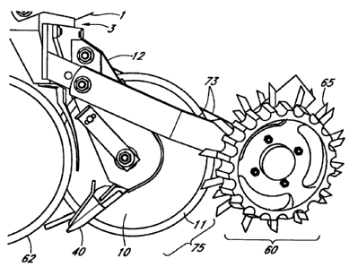
Figure 2 shows the relative mounting of the single disc fertilizer opener 75
to the
planter row unit front face plate 3. In figures 2 and 3, the single disc
fertilizer
opener 75 has been mounted in combination with a row cleaner 60 to row unit
face plate 3. For ease of viewing, liquid fertilizer storage tanks and lines
have not
been included in the enclosed drawings as those practiced in the arts are well
versed in storage and supply of liquid fertilizers for incorporated
application. As
shown in Figure 3, the compact offset design of the fertilizer disc opener
assembly 75 does not interfere with operation of either the row cleaner 60 or
the
seed vee-opener blades 63 of the planter row unit 1, even when mounted in the
mounting area provided by the row unit front face plate 3. This compact but
sturdy configuration allows the fertilizer feed shoe 40 to maintain its pre-
set
spatial distance from the seed furrow created by the vee-openers 63 during
operation over various terrains. As shown, the fertilizer feed shoe 40 may be
set
to deliver liquid fertilizer within one inch of the seed furrow created by vee
openers 63.
19
CA 02557928 2006-08-29
Figure 4 provides an exploded view of the invention as shown in Figure 3. This
view specifically illustrates another improvement provided herein. Reference
is
specifically made herein to U.S. Patent 4,796,550 issued to Van Natta et al
for a
"Single Angled Blade Coulter and Fertilizer Opener." As taught by the Van
Natta reference, adjustment to the tapered bearings as required by normal wear
and use of the disc assembly 75 would require removal of a tapered cotter pin
from a notch in the shaft assembly before the nuts holding the disc assembly
in
place could be drawn down to pull the shaft through the bearing assembly and
thus tighten the disc on the shaft assembly. Because of the difficult
conditions
that this assembly is subjected to, the removal of a cotter pin from a tapered
slot
is complicated by wear, rust and impacted dirt. The present art allows for a
simple adjustment of the tapered bearings 28 by simply tightening disc axle
bearing wear adjustment nut 43. Another advantage of this improved tightening
method is that adjustment of the shaft and tapered bearing 28 does not require
exposing the internal portions of the tapered bearing. This improved
maintenance feature is allowed by using step washer 17 with insert groove 53.
Tightening disc axle bearing wear adjustment nut 43 pulls the double-threaded
end disc axle 13 through the tapered bearing 28 thereby removing the gap or
slack caused by wear in the axle 13 or tapered bearing 28.
The fertilizer feed shoe spring 47 as shown in Figure 4 when installed is
coiled
around axle support tube 18. The pre-installation angle between opposing
CA 02557928 2006-08-29
members of the fertilizer feed shoe spring is 105-110 degrees. After
installation,
the opposing members have an approximate angle of 90 degrees. The top
member is fixed to the disc support beam. The other member fits into
engagement slot 46 of fertilizer feed shoe 40 at the ninety degree angle
defined as
the fertilizer feed tube shoe spring anti-rotation end 52. This ninety degree
angle
locks the fertilizer feed shoe 40 in position. The result of installing the
coiled
fertilizer feed shoe spring 47 under load and including fertilizer feed tube
shoe
spring anti-rotation end 52 is to bias the fertilizer feed shoe 40 towards
both disc
and against the bottom of the furrow during operation.
Figures 5-9 illustrate the invention as mounted to the row units found on the
left
side of a planter. Figures 10-14 illustrate the invention as mounted to the
row
units found on the right side of a planter. Figure 5 provides a left side view
of a
left side row unit fertilizer disc opener assembly 75 which is primarily
composed
of sub-assemblies for angularly mounting the disc 10, the furrow closing strap
30
and the fertilizer feed tube shoe 40. Row unit mounting bracket plate 4 is
attached to the planter row unit at the row unit front face plate 3 by
inserting
mounting bracket plate bolts 5 and through mounting bracket bolt holes 6. Disc
hub support beam 12 is engaged and attached to mounting bracket support beam
side plate 7 by support beam attachment bolts 14 inserted through bracket
support beam side plate bolt holes 8, washers 21 and nuts 20 for affixation.
The
depth of the disc 10 may be adjusted for three depths. When the top bracket
21
CA 02557928 2006-08-29
support beam side plate bolt holes 8 are engaged, the depth of disc 10 is pre-
set
to cut a maximum of three-quarter inch above where the seed will be deposited.
Selecting the middle bracket support beam side plate bolt holes 8 for
securement
sets the depth of disc 10 equal to the depth at which the seed will be
planted.
Selecting the bottom bracket support beam side plate bolt holes 8 for
securement
sets the depth of disc 10 equal to three-quarter inch below the depth at which
the
seed will be planted. As illustrated by Figure 5, furrow strap mounting
bracket
31 attaches and aligns the furrow strap 30 to the disc opener assembly 75
through double-threaded end disc axle 13. Furrow strap bracket support nut 15
and washer 16 affixed the position of the furrow strap mounting bracket 31 in
relation disc 10. Furrow strap 30 which supports creation of the furrow made
by
disc 10 is composed of furrow strap stiffener 34 which provides a rigid back
to an
elastic insert 36 which contacts the soil during operation. Insert 36 may be
composed of any number of rubber or plastic materials which allow a
combination of wear resistance and flexibility. The combination of stiffener
34
and elastic insert 36 serve to give furrow control strap 30 the necessary
resiliency
to minimize disruption of the soil as the fertilizer furrow is created by disc
10 for
deposition of liquid fertilizer. As illustrated by figure 5, fertilizer feed
tube 41 is
mounted to fertilizer feed tube shoe 40 (not shown) and fertilizer feed shoe
soil
engagement tip 42 extends past the periphery of disc 10. Similarly, Figure 10
provides a left side view of a right side row unit fertilizer disc opener
assembly
22
CA 02557928 2006-08-29
75 which is pr-imarily composed of sub-assemblies for angularly mounting the
disc 10, the furrow control strap 30 and the fertilizer feed tube shoe 40.
Figure 6 provides a right side view of a left side row unit fertilizer disc
opener
assembly 75. Disc 10 is configured to rotate around double-threaded end disc
axle 13 (not shown) which is inserted through axle support tube 18 (not shown)
and attached to the lower end of substantially vertical disc hub support beam
12.
The outside edge of fertilizer feed tube pocket 48 forms a J-shape and when
affixed to disc hub support beam 12 by welding, improves the structural
strength
of the disc assembly 75 while also creating a protective pocket for fertilizer
feed
tube shoe 40. The bottom front portion of fertilizer feed tube 40 forms
fertilizer
feed tube shoe cantilever end 44 that pivotably rests against the inside of
the
lower aft portion of fertilizer feed tube pocket 48. Above the fertilizer feed
tube
shoe cantilever end 44 is fertilizer feed shoe spring engagement slot 46 for
engagement of fertilizer feed shoe spring 47 which is installed under load.
By assembling fertilizer feed tube shoe 40 under load, fertilizer feed tube
shoe
spring 47 is biased against both disc 10 and the bottom of the furrow created
by
disc 10.
The disc axle strap depth control keyed and threaded end 51 is inserted
through
furrow depth control lever 23 and affixed in place by disc axle bearing wear
adjustment nut 43. As shown in Figure 6, fertilizer feed tube 41 is affixed to
the
top of fertilizer feed tube shoe 40 for discharge of the liquid fertilizer
within the
23
CA 02557928 2006-08-29
furrow created by the disc. Fertilizer feed tube shoe furrow control edge 45
provides a u-shaped fertilizer furrow and keeps the furrow open until the
liquid
fertilizer is delivered from feed tube discharge end 49 into the bottom of the
furrow past the outside periphery of disc 10. Similarly, Figure 11 provides a
right
side view of a right side row unit fertilizer disc opener assembly 75 which is
primarily composed of sub-assemblies for angularly mounting the disc 10, the
furrow strap 30 and the fertilizer feed tube shoe 40.
Figure 7 provides a front perspective view of a left side row unit fertilizer
disc
opener assembly 75. As shown in Figure 7, the disc support beam 12 is mounted
between both mounting bracket support beam side plates 7. Support beam
attachment bolts 14 are inserted through mounting bracket support beam side
plate bolt holes 8 and support beam adjustment shim 9 to affix disc hub
support
beam 12 to the mounting bracket plate 4. The configuration shown in Figure 7
places the fertilizer two inches from the center of the seed furrow. Placing
and
securing the disc hub support beam on either side of mounting bracket support
beam side plates 7 allows the liquid fertilizer to be placed either one inch
or three
inches from the center of the seed furrow. Support beam adjustment shim 9
allows the same bolts to be used and fixes the spacing of the components.
The disc assembly 75 may also be adjusted to increase or decrease the depth of
fertilizer placement. Selection of any two of the mounting bracket support
beam
side plate bolt holes 8 allows the disc depth to be set equal to the planter
row
24
CA 02557928 2006-08-29
unit vee-opener blades, which places the fertilizer at the same depth as the
seed.
The fertilizer may also be placed three-quarter inch above or below the depth
of
the seed. Similarly, figure 12 provides a right side view of a right side row
unit
fertilizer disc opener assembly 75 which is primarily composed of sub-
assemblies
for angularly mounting the disc 10, the furrow strap 30 and the fertilizer
feed
tube shoe 40. As shown in Figure 12, the disc hub support beam 12 is mounted
between both mounting bracket support beam side plates 7 but may also be
configured for selected offsets from the center of the seed furrow or pre-
selected
depths.
Figure 8 provides a rear perspective view of a left side row unit fertilizer
disc
opener assembly 75. As shown in Figure 8, disc hub support beam 12 is parallel
to the planter row unit 1 direction of travel. Disc axle support tube 18 is
mounted
to disc hub support beam 12 at a four degree angle by disc axle support tube
support weld 19 and double-threaded end disc axle 13 is inserted through disc
axle support tube 18. Furrow control strap 30, disc 10 and fertilizer feed
shoe 40
are then mounted upon disc axle support tube 18 or double-threaded end disc
axle 13 in parallel to each other but at a four degree angle to the planter
row unit
direction of travel. This configuration ensures accurate placement of the
liquid
fertilizer both in relation to the fertilizer furrow and the seed furrow
during
operation. This figure also illustrates the importance of furrow control strap
30 to
achieving the objectives of the row unit fertilizer disc opener assembly 75.
The
CA 02557928 2006-08-29
furrow control strap 30 mounted against the flat side of the disc 10 serves to
minimize build-up on the outside of the disc and aids in minimizing disruption
of the soil surrounding the fertilizer furrow. The combination of minimal seed
furrow disruption and segregation of the seed and fertilizer furrows provides
desired depth and spatial placement of liquid starter fertilizer during
planting
operations. The position of the furrow control strap 30 may also be adjusted
via
furrow strap adjustment lever 23 and furrow strap adjustment lever setting
bolt
24. Similarly, figure 13 provides a right side view of a right side row unit
fertilizer disc opener assembly 75 which is primarily composed of sub-
assemblies
for angularly mounting the disc 10, the furrow strap 30 and the fertilizer
feed
tube shoe 40.
Figure 9 provides a front perspective view of a left side row unit fertilizer
disc
opener assembly 75. Figures 8 and 9 also illustrate the beneficial structural
features allowed by fertilizer feed tube pocket 48. As shown in figure 8, the
steel
structure of fertilizer feed tube pocket 48 serves as a shield against
undesirable
materials and reduces contact between the fertilizer feed tube assembly 40 and
said materials. The front interior edge of fertilizer feed tube protective
pocket 48
is in close proximity to the disc 10 and acts as a scraper. As shown in figure
9, the
J shape of the front edge of the fertilizer feed tube pocket 48 serves to
strengthen
the disc hub support beam 12 against side loading forces. Similarly, figure 14
provides a front perspective of a right side row unit fertilizer disc opener
26
CA 02557928 2006-08-29
= =
assembly 75 which is primarily composed of sub-assemblies for angularly
mounting the disc 10, the furrow strap 30 and the fertilizer feed tube shoe
40.
Figure 15 better illustrates the fertilizer feed shoe 40. The outer edge of
the single
disc blade 10 is flat and the inner portion is beveled 11. The beveled edge of
the
disc 11 cuts a furrow for insertion of the spring loaded fertilizer feed tube
shoe 40
within the furrow. The fertilizer feed tube shoe spring 47 is pre-loaded
during
assembly so that the fertilizer feed tube shoe 40 is biased both to the bottom
of
the furrow and against the interior of the disc 10. The lower front portion of
the
fertilizer feed tube shoe 44 rests against the lower aft portion of the
fertilizer feed
tube pocket 48. This configuration allows the fertilizer feed tube shoe 40 to
maintain its substantially horizontal orientation but pivot upward in the
event of
an over load condition i.e. contact with a stone or clod, thereby preventing
catastrophic failure.
The spring loaded fertilizer feed shoe 40 has a generally low profile to
minimize
soil disruption with a length that is substantially greater than its width and
height. In the preferred embodiment, the fertilizer feed shoe 40 is six inches
long
when paired with a disc 10 having a fourteen inch diameter. The fertilizer
feed
shoe 40 has both an active inner and outer surface. The inner surface is
substantially flat and is biased against the disc 10 to act as a disc scraper.
The
fertilizer feed tube shoe furrow control edge 45 forms the outer surface of
the
fertilizer feed tube shoe 40 and has an arcuate surface with a decreasing
radius
27
CA 02557928 2006-08-29
which ends as a straight edge providing the fertilizer feed tube shoe 40 with
a
knife like edge to engage the lower inside portion of the furrow. The
fertilizer
feed tube shoe furrow control edge 45 is substantially horizontal during soil
engagement. Fertilizer feed shoe soil engagement tip 42 forms the outer
portion
of the fertilizer feed tube shoe furrow control edge 45 extending past the
periphery of the disc 10. The inner portion of the fertilizer feed shoe soil
engagement tip 42 facing the disc is substantially flat. The outer portion of
the
fertilizer feed shoe soil engagement tip 42 also forms a knife like edge
having a
decreasing arcuate radius along its length and ending as a u-shape at the
outer
most engagement tip. During operation, the disc 10 and fertilizer feed tube
shoe
furrow control edge 45 in combination produce a u-shaped furrow having a
bottom width substantially equivalent to its top width. The combination of
decreasing radii along the fertilizer feed shoe soil engagement tip 42 and
fertilizer feed tube shoe furrow control edge 45 hold the furrow created by
the
disc 10 open and shape the furrow to allow even discharge and distribution of
the liquid fertilizer from the fertilizer feed tube discharge end 49 therein
at the
fertilizer feed shoe soil engagement tip 42 with a minimum of soil disruption.
Although preferred forms of the invention have been described above, it is to
be
recognized that such disclosure is by way of illustration only, and should not
be
utilized in a limiting sense in interpreting the scope of the present
invention.
Obvious modifications to the exemplary embodiments, as hereinabove set forth,
28
CA 02557928 2006-08-29
could be readily made by those skilled in the art without departing from the
spirit of the present invention.
The inventors hereby state their intent to rely on the Doctrine of Equivalents
to
determine and assess the reasonably fair scope of their invention as pertains
to
any apparatus not materially departing from but outside the literal scope of
the
invention as set out in the following claims.
29