Note: Descriptions are shown in the official language in which they were submitted.
CA 02557937 2006-08-29
WO 2005/089050 PCT/1B2005/000589
1
Enhanced Uplink Dedicated Channel - Application protocol over lub/lur
BACKGROUND OF THE INVENTION
1. Field the Invention
The present invention relates to an enhanced mobile communications
uplink (the direction of the radio link from the user equipment to the
network) and, more particularly, to the content of messages needed
between a third generation a radio network controller (RNC) and base
station (Node B) to carry out the enhancement within a mobile
communications network.
2. Discussion of Related Art
To enhance the DCH (Dedicated Channel) performance, the Third
Generation Partnership Project (3GPP) agreed on a Release 6 Study Item,
'Uplink Enhancements for Dedicated Transport Channels' in October 2002.
The justification of the study item was that since the use of IP (Internet
Protocol) based services is becoming more important there is an increasing
demand to improve the coverage and throughput as well as to reduce delay
in the uplink. Applications that could benefit from an enhanced uplink (UL
E-DCH) may include services like video-clips, multimedia, e-mail,
telematics, gaming, video-streaming, etc. This study item investigates
enhancements that can be applied to UMTS (Universal Mobile
Telecommunications System) Terrestrial Radio Access (UTRA) in order to
improve the performance on uplink dedicated transport channels.
The study includes the following topics related to enhanced uplink for
UTRA FDD (Frequency Division Duplex) to enhance uplink performance in
CA 02557937 2006-08-29
WO 2005/089050 PCT/1B2005/000589
2
general or to enhance the uplink performance for background, interactive
and streaming based traffic:
Adaptive modulation and coding schemes
Hybrid ARQ (Automatic Repeat Request) protocols
Node B controlled scheduling
Physical layer or higher layer signaling mechanisms to support the
enhancements
Fast DCH setup
Shorter frame size and improved QoS (Quality of Service)
This UL E-DCH can be compared to HSDPA (High Speed Downlink Packet
Access) since HSDPA was for a similar enhancement in the downlink (DL).
SUMMARY OF THE INVENTION
In this invention disclosure, signalling over the interfaces (lub/lur) between
the 3GPP radio network controller (RNC) and Node B and between RNCs,
including parameters, is shown to support the air interface enhancement on
UL DCHs.
Currently no description can be found from 3GPP specifications or
technical reports as to what kind of parameters should be added in which
messages in the lub/lur application protocol to support UL E-DCH. The
present invention defines the basic Information Elements (lEs), which
should be provided to set up and to support E-DCH functionality in the
network on lub/lur.
Thus the goal of this invention is to provide general signalling methods for
the lub/lur interface between the RNCs and the Node Bs in order to be able
to setup and re-configure the UL E-DCH channel. It is another object to do
so with maximum flexibility so as not to be restricted to any particular
CA 02557937 2013-10-25
message, but to be later applicable to any selected message or messages in the
yet undefined protocol.
According to a first aspect of the present invention, there is provided a
method
comprising: receiving information having both a cell specific parameter and a
radio link specific parameter, in respective messages on an interface between
a
base station and a radio network controller for configuring a radio uplink
from a
user equipment to the base station; configuring the radio uplink at the base
station; and receiving a payload packet from the user equipment to the base
station over the radio uplink after the radio uplink is configured at the base
station, wherein at least one of said respective messages enables said
configuring the radio uplink, and wherein the cell specific parameter
comprises
an information element indicating a total allowable uplink interference for
the
base station, and the radio link specific parameter comprises at least one of
an
information element indicating the power offset of acknowledgement
transmission to the user equipment and an information element indicating the
power offset of rate grant signaling to the user equipment.
In further accord with the first aspect of the present invention, the method
further
comprises the steps of acknowledging correct reception of the payload packet
at
the network element on a radio downlink from the network element to the user
equipment, and sending the payload packet from the base station to the radio
network controller following the correct reception from the user equipment.
According to a second aspect of the present invention, there is provided a
method comprising: sending an information element having both a cell specific
parameter and a radio link specific parameter, in respective messages on an
interface to a base station from a radio network controller for configuring a
radio
uplink from a user equipment to the base station; and receiving a payload
packet from the base station after the payload packet has been sent from the
user equipment to the base station over the radio uplink that has been
3
CA 02557937 2013-10-25
configured, wherein at least one of said respective messages enables said
configuring the radio uplink, wherein prior to said sending said information
on
said interface between said base station and said radio network controller,
said
radio network controller decides a value for said cell specific parameter or
said
radio link specific parameter, or both, for said sending said information with
said
cell specific parameter and said radio link specific parameter in said
respective
messages on said interface from said radio network controller to said base
station, and wherein the cell specific parameter comprises an information
element indicating a total allowable uplink interference for the base station,
and
the radio link specific parameter comprises at least one of an information
element indicating the power offset of acknowledgement transmission to the
user equipment and an information element indicating the power offset of rate
grant signaling to the user equipment.
In still further accord with the second aspect of the present invention, the
method
further comprises the step of sending the information element on an interface
between the radio network controller and another radio network controller for
relay to another base station for configuring an uplink between the other base
station and the user equipment.
According to a third aspect of the present invention, there is provided an
apparatus comprising: a first interface configured to communicate information
having both a cell specific parameter and a radio link specific parameter in
respective messages to a base station from the apparatus in order to configure
a radio uplink from user equipment to the base station; and a second interface
configured to communicate the information between the apparatus which is a
radio network controller and a second radio network controller connected to a
second base station, wherein at least one of said respective messages is
arranged to enable said configuring the radio uplink, wherein prior to
communicating said information on said first interface between said base
station
and said apparatus, said apparatus is configured to decide a value for said
cell
4
CA 02557937 2013-10-25
specific parameter or said radio link specific parameter, or both, for sending
said
information with said cell specific parameter and said radio link specific
parameter in said respective messages on said first interface from said
apparatus to said base station, and wherein the cell specific parameter
comprises an information element indicating a total allowable uplink
interference
for the base station, and the radio link specific parameter comprises at least
one
of an information element indicating the power offset of acknowledgement
transmission to the user equipment and an information element indicating the
power offset of rate grant signaling to the user equipment.
According to a fourth aspect of the present invention, there is provided an
apparatus comprising: a first means for communicating information having both
a cell specific parameter and a radio link specific parameter in respective
messages between the apparatus, which is a base station, and a radio network
controller for configuring an uplink channel on a radio link; and a second
means
for communicating signals related to said configuring the uplink channel
between the base station and the user equipment, and arranged to receive a
payload packet from the user equipment to the base station over the radio link
after said configuring the uplink channel on the radio link is carried out by
the
base station, wherein the first means is also for conveying the payload packet
from the base station to the radio network controller following the reception
by
the base station from the user equipment, wherein at least one of said
respective message is arranged to enable said configuring the uplink, and
wherein the cell specific parameter comprises an information element
indicating
a total allowable uplink interference for the base station, and the radio link
specific parameter comprises at least one of an information element indicating
the power offset of acknowledgement transmission to the user equipment and
an information element indicating the power offset of rate grant signaling to
the
user equipment.
CA 02557937 2013-10-25
According to a fifth aspect of the present invention, there is provided an
apparatus comprising: a first interface arranged to communicate information
having both a cell specific parameter and a radio link specific parameter in
respective messages between the apparatus, which is a base station, and a
radio network controller in order to configure an uplink channel on a radio
link;
and a second interface arranged to communicate signals related to said
configuring the uplink channel between the base station and the user
equipment, and arranged to receive a payload packet from the user equipment
to the base station over the radio link after said configuring the uplink
channel on
the radio link is carried out by the base station, wherein the first interface
is also
arranged to convey the payload packet from the base station to the radio
network controller following the reception by the base station from the user
equipment, wherein at least one of said respective messages is arranged to
enable said configuring the uplink, and wherein the cell specific parameter
comprises an information element indicating a total allowable uplink
interference
for the base station, and the radio link specific parameter comprises at least
one
of an information element indicating the power offset of acknowledgement
transmission to the user equipment and an information element indicating the
power offset of rate grant signaling to the user equipment.
According to a sixth aspect of the present invention, there is provided an
apparatus comprising: a transceiver configured to receive and transmit signals
over an interface between the apparatus, which is a user equipment, and a base
station; and a control arranged to process signalling between the base station
and the user equipment in order to configure a radio uplink from the user
equipment to the base station according to at least a radio link specific
parameter conveyed in information having both a cell specific parameter and a
radio link specific parameter in respective messages on an interface between
the base station and a radio network controller, wherein the cell specific
parameter comprise an information element indicating the total allowable
uplink
interference for the base station, and the radio link specific parameter
comprises
6
CA 02557937 2013-10-25
at least one of an information element indicating the power offset of
acknowledgement transmission to the user equipment and an information
element indicating the power offset of rate grant signaling to the user
equipment,
wherein the user equipment is configured to send a payload packet from the
user equipment to the base station over the radio uplink after the radio
uplink is
configured.
According to a seventh aspect of the present invention, there is provided a
system comprising: a base station and a radio network controller connected by
a
signalling interface and arranged to configure a first radio uplink from a
user
equipment to the base station, the signaling interface being arranged to
convey
messages having information elements that contain parameters from the radio
network controller to the base station, wherein the information elements have
both a cell specific parameter and a radio link specific parameter, and are
conveyed in respective messages on the signaling interface between the base
station and the radio network controller, wherein the user equipment is
arranged
to send a payload packet to the base station over the first radio uplink after
the
first radio uplink is configured at the user equipment for sending the payload
packet to the radio network controller, wherein at least one of said
respective
messages is arranged to enable said configuring the first radio uplink,
wherein
the information elements are arranged to configure a second radio uplink
between the base station and the user equipment, the first radio network
controller being configured to receive a payload packet from the base station
over the signaling interface, the second radio network controller being
configured to redeive the payload packet from the second base station after
receipt by the base station from the user equipment over the second radio
uplink, and the radio network controller being configured to send the payload
packet received from the base station to the radio network controller
following
the reception by the base station from the user equipment for transfer from
the
radio network controller, and wherein the cell specific parameter comprises an
information element indicating a total allowable uplink interference for the
base
7
CA 02557937 2013-10-25
station, and the radio link specific parameter comprises at least one of an
information element indicating the power offset of acknowledgement
transmission to the user equipment and an information element indicating the
power offset of rate grant signaling to the user equipment.
According to an eighth aspect of the present invention, there is provided a
non-
transitory computer readable medium embodying a data structure for access by
computer readable code being executed by a CPU, the data structure
comprising: information having both a cell specific parameter and a radio link
specific parameter to be transferred in respective messages on an interface
between a base station and a radio network controller in order to configure a
radio uplink from a user equipment to the base station, wherein said
configuring
is carried out in order to enable transmission of a payload packet from the
user
equipment to the base station over the radio uplink and from the base station
to
the radio network controller, wherein at least one of said respective messages
is
arranged to enable said configuring the radio uplink, and wherein prior to
said
transferring of said information on said interface between said base station
and
said radio network controller, said radio network controller decides a value
for
said cell specific parameter or said radio link specific parameter, or both,
for said
sending said information with said cell specific parameter and said radio link
specific parameter in said respective messages on said interface from said
radio
network controller to said base station.
7a
CA 02557937 2013-10-25
According to a ninth aspect of the present invention, there is provided a non-
transitory computer readable medium embodying a data structure for access by
computer readable code being executed by a CPU, the data structure
comprising: information having both a cell specific parameter and a radio link
specific parameter for transfer in respective messages on an interface between
a base station and a user equipment in order to configure a radio uplink from
the
user equipment to the base station, wherein said configuring is carried out at
the
base station, for enabling transmission of a payload packet from the user
equipment to the base station over the radio uplink and from the base station
to
a radio network controller, wherein at least one of said respective messages
is
arranged to enable said configuring the radio uplink, and wherein prior to
said
sending said information on said interface between said base station and said
radio network controller, said radio network controller decides a value for
said
cell specific parameter or said radio link specific parameter, or both, for
said
sending said information with said cell specific parameter and said radio link
specific parameter in said respective messages on said interface from said
radio
network controller to said base station.
These and other objects, features and advantages of the present invention will
become more apparent in light of a detailed description of a best mode
embodiment thereof which follows, as illustrated in the accompanying drawing.
7b
CA 02557937 2006-08-29
WO 2005/089050 PCT/1B2005/000589
8
BRIEF DESCRIPTION OF THE DRAWINGS
Fig. 1 shows signalling between the interfaces (lub/lur) between the 3GPP
network element called "Node B" (or "base station") and radio network
controller (RNC) and between RNCs, including parameters, according to
the present invention, to support the air interface uplink enhancement.
Fig. 2 shows a prior art packet transmission on a radio uplink from a User
Equipment (UE) to a Radio Network Controller (RNC) via a Node B which
is comparable to a base station of a second generation system and a
retransmission of the packet upon receiving a negative acknowledgement
from the RNC to the UE.
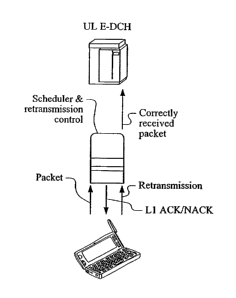
Fig. 3 shows a proposal, according to an enhanced uplink dedicated
channel (E-DCH) concept to enhance the uplink by moving the scheduler
and retransmission control from the RNC to the Node B but which proposal
has not yet explained the information elements and parameters needed for
exchange between an RNC and a Node B and between RNCs.
Fig. 4 shows a User Equipment (UE) such as the user equipment of Figs. 1
and 3, according to the present invention.
DETAILED DESCRIPTION OF INVENTION
An enhanced uplink dedicated channel is currently proposed in 3GPP
standardization committees in order to provide uplink enhancements for
Dedicated Transport Channels. In relation to enhanced uplink for UTRA
FDD (Frequency Division Duplex) uplink performance may be enhanced by
improved Hybrid ARQ (Automatic Repeat Request) protocols and Node B
CA 02557937 2006-08-29
WO 2005/089050 PCT/1B2005/000589
9
controlled scheduling. Physical layer or higher layer signaling mechanisms
may also be provided to support the enhancements.
An UL E-DCH can be compared to HSDPA (High Speed Downlink Packet
Access) since HSDPA was for a similar enhancement in the downlink (DL).
Fig. 2 shows a payload packet sent from a User Equipment (UE) over an
uplink radio interface to a base station (Node B) and from there to a Radio
Network Controller (RNC) connected to the Node B by means other than a
radio link. The RNC replies with a radio link control (RLC)
acknowledgment, indicating either success (ACK) or failure (NACK) in
receipt of the payload packet. By "payload" is meant information distinct
from configuration information such as setup, scheduling or retransmission
control signalling, i.e., for use by the user of the user equipment after
setup
or reconfiguration in an application such as a web page, video, text, etc.
Thus, preceding any exchange of payload information there will be a
distinct configuration setup, scheduling, or retransmission control signalling
procedure. Examples of third generation signalling procedures are shown
in detail in 3GPP TR 25.931 v5.1.0 (2002-06).
Fig. 3 shows a proposal, according to an enhanced uplink dedicated
channel (E-DCH) concept. One aspect of the improvement is to enhance
the uplink by moving the acknowledgement function from the RNC to the
Node B. The acknowledgement function is a known retransmission control
function that is normally controlled at the RNC and need not be described
here. What is important here is the network entity selected to perform this
function. The E-DCH concept helps reduce delays by making the Node B
take on control of this important function closer to the UE. The E-DCH
proposal has not yet explained the information elements and parameters
needed to be exchanged in the above-mentioned distinct signalling
procedures between an RNC and a Node B, between the Node B and the
user equipment, and also between RNCs in order to carry out such a
change.
CA 02557937 2006-08-29
WO 2005/089050 PCT/1B2005/000589
Another aspect of the E-DCH concept is "fast" Node B configuration control
for uplink scheduling/loading. In other words, instead of the RNC, the Node
B would be in configuration control of scheduling and/or congestion. Again,
5 this reduces delays. The RNC sends information about the user equipment
capabilities, cell specific parametrization and user equipment specific
parametrization information related to E-DCH to the Node B. The
configuration capabilities signalled might for instance include the number of
HARQ processes, the modulation supported, the maximum data rate, etc.
10 The cell specific parametrization could include setting up shared
control
channels, allocation of hardware and power resources for E-DCH, etc. The
user equipment specific parametrization could include maximum data rate
RNC allows the Node B to allocate to the UE, the power offsets and
signalling repetition factors to be used for signalling to that UE and by that
UE etc. Generally, the user equipment may send signalling to the Node B
to assist the Node B scheduler and the Node B may send signalling back to
the user equipment that informs the user equipment of its data rates or
limits them. Thus, the user equipment may (or may not) signal the Node B
information to help the Node B scheduler. As examples, the user
equipment could request a data rate from the Node B or it could just send
information on how much data it has and how much transmit power it is
able to use. The Node B may (or may not) signal the scheduling
commands to the UE. For instance, the Node B could signal the user
equipment with a (maximum) data rate. This maximum data rate might
then be valid until a new one is signalled by the Node B, or for a specific
time period; or, it may change according to some specific rules, e.g.,
related to the usage of data rates.
Fig. 1 shows an exchange of information elements and parameters in such
a distinct configuration signalling procedure such as a setup procedure.
Configuration messages are exchanged between a Radio Network
Controller (RNC) which in this case is shown as a "serving" RNC 130 and
CA 02557937 2006-08-29
WO 2005/089050 PCT/1B2005/000589
11
a so-called "Node B" 132, according to the present invention, for
configuring an enhanced uplink dedicated channel (E-DCH) for a User
Equipment 160. The Node B 132 is a third generation base station.
Between the SRNC 130 and the Node B 132 is a so-called tub interface
(non-radio). According to the present invention, configuration messages for
E-DCH are defined for exchange over the lub interface, for example, on a
signalling line 133 from the SRNC 130 to the Node B 132 and on a
signalling line 134 in the reverse direction from the Node B 132 to the
SRNC 130.
As known in the art, when the UE moves into the range of another Node B
110 which may be connected to another RNC 100, there may be a need for
communication of signalling similar to that exchanged over the lub interface
lines 133, 134 over a so-called lur interface between the SRNC 130 and
another RNC 100 which may be designated a "drift" RNC (DRNC)
connected to the other Node B 110. Between the SRNC 130 and the
DRNC 100, a configuration setup message signal is shown on a line 150
from the SRNC 130 to the DRNC 100 and a configuration setup message
signal in the reverse direction is shown on a line 140 between the DRNC
100 and the SRNC 130. These signals are provided over a so-called lur
interface which is a non-radio interface. A message signal is shown on a
line 120 from the DRNC 100 to the other Node B and a message signal in
the reverse direction is shown on a line 122 from the Node B 11010 the
DRNC 100. Together, these signals form another lub interface which is
also a non-radio interface. For a given situation, the information elements
and parameters of the present invention may be carried over one or all of
these lur and lub interfaces. It should be understood that the example
given is not exhaustive as will be made clear by reference to 3GPP TS
25.931. The other Node B 110 is shown in communication with the UE 160
via a radio downlink 170 and a radio uplink 180. Similarly, the Node B 132
is shown in communication with the UE 160 via a radio downlink 135 and a
radio uplink 136.
CA 02557937 2006-08-29
WO 2005/089050 PCT/1B2005/000589
12
For background information, in third generation systems, it will thus be
understood, the RNC 130 may be in communication with another RNC 100
which may, with respect to a given UE, be a Drift RNC (DRNC) or a
Serving RNC (SRNC) over the so-called lur interface. The SRNC 130 of
Fig. 1 is the "serving" RNC for UE 160. It is connected to other Node Bs
(not shown) in other cells. The UE 160 is currently located in the cell of one
of the Node Bs connected to the SRNC 130 and is in radio communication
with that Node B as well as the Node B 110 because it may be in proximity
to the other Node B 110. The UE 160 is currently being "served" by the
SRNC 130. The UE 160 may however be travelling toward the cell of Node
B 110 connected to RNC 100 (called the "drift" RNC) and could be handed
over to that cell. The UE would then either be "served" by RNC 100 and
RNC 100 would become the SRNC for the UE or the RNC 130 may still
continue "serving" the UE i.e. functioning as SRNC and the RNC 100 would
still remain as "drift" RNC. By establishing the lur interface, the third
generation improves over the "hard-handover" situation of the second
generation by providing the UE the ability to communicate with multiple
Node Bs at the same time. A "soft-handover" is thereby enabled that does
not require re-synchronization and, unlike second generation systems,
makes the handover imperceptible to the user. For purposes of the present
invention, however, the details of the soft handover process is secondary.
The important thing here is the nature of the parameters disclosed below
and transmitted in information elements contained in messages transmitted
over the lur/lub interface.
The message signal on the line 122 from the Node B 110 may therefore be
forwarded on a line 140 to the SRNC 130. Likewise, the message signal on
the line 120 from the RNC 100 most likely would have originated as a
signal on a line 150 from the SRNC 130 to the RNC 100 and forwarded
from there on the line 120 to the Node B 110.
CA 02557937 2006-08-29
WO 2005/089050 PCT/1B2005/000589
13
Fig. 4 shows the UE of Fig. 1 or Fig. 3 at a level of detail sufficient to
show
the elements needed to carry out the present invention. The UE 160
includes a receiver 190 responsive to the downlink 170 from the Node B
110 and the downlink 138 from the Node B 132. The UE 160 also includes
a transmitter 192 for providing the uplink 180 from the UE to the Node B
110 and the uplink 136 from the UE 162 the Node B 132. A retransmission
control 194 provides a signal on a line 196 to the transmitter 192 and
receives a signal 198 from the receiver 190. Referring both to Figs. 3 and
4, an acknowledge/negative acknowledge signal may be received on one
or both of the downlinks 138, 170 by the receiver 190 which in turn
provides the received signal on the line 198 to the retransmission control
194. The retransmission control in turn evaluates the acknowledgement or
negative acknowledgement signal and decides whether a retransmission is
required or not. If a retransmission is required, the retransmission control
sees to it that the retransmission is provided on the signal line 196 to the
transmitter 192 which in turn transmits a retransmission on one or both of
the uplinks 136, 180. The retransmission control 194 can be viewed as a
transmission control or a transmission/retransmission control. In other
words, a packet is transmitted, retransmitted or both by the control 194.
It should be realized that although a majority of the configuration
parameters disclosed herein are disclosed in a way that is more related to
how the Node B is to control the data rate of the UE, it is quite possible for
the UE to control or have a role in the control of its own data rate. It can
be
possible for the UE control 194 to take care of not only
transmission/retransmission but also data rate adjustments and timing of
the transmissions based on the control information received in the
downlink.
The present invention discloses various information elements and
parameters in general terms without necessarily specifying exactly which
existing or new message signal is to be used to communicate the
CA 02557937 2006-08-29
WO 2005/089050 PCT/1B2005/000589
14
information elements and parameters. There are of course numerous
existing messages that may be used for conveying the disclosed
information elements (lEs) and parameters and some of them are
mentioned hereafter as candidates but it is foreseen that others may be
used as well some of which may not yet be defined. One of the more
important decisions yet to be made involves which network entity, node, or
element will decide the values of parameters.
A radio network controller, according to the present invention, has an E-
DCH configuration signalling interface comprising the information elements
and parameters described in further detail below and exchanged over the
lub lines 133, 134 or over the lur lines 140, 150, or both. A Node B,
according to the present invention, has an E-DCH configuration signalling
interface comprising the information elements and parameters described in
further detail below and exchanged over the lub lines 133, 134 or 120, 122.
A system, according to the present invention, has one or more radio
network controllers and at least one Node B each with an E-DCH
configuration signalling interface as described above and comprising the
information elements and parameters described in further detail below.
Depending on which network node will decide the values of the
parameters, the following cases can be considered:
1) The RNC decides the value and informs Node B. Node B follows the
decision. Even though the Node B may now be taking on functions that
were previously the RNC's responsibility, it does not work completely
independently. The RNC provides the Node B with a set of parameters
according to which it should then perform these functions. One could think
of the RNC as a manager and Node B as the worker working according to
the guidelines and on the UEs the RNC has commanded the Node B to
work on. But the manager is always right and in overall control.
CA 02557937 2006-08-29
WO 2005/089050 PCT/1B2005/000589
2) The RNC gives the boundaries within which choices may be made by
Node B. Node B can decide the value according to its present condition
within the boundaries given. The RNC could signal the UE capabilities,
such as its maximum supported data rate capability, to the Node B, but as
5 well it should signal some parametrization like how Node B resources are
to be allocated for E-DCH, what are the repetition factors and power offsets
etc. to be used for that UE, what is the maximum data rate currently
allowed by the RNC to be given to the UE, etc.
10 3) Node B proposes a value to RNC and RNC confirms or decides the
value. (In this case RNC has freedom not to accept Node B's proposal.)
4) Node B decides the value dynamically and RNC doesn't need to know it.
15 5) Others can certainly be contemplated as well and these are just
examples.
It should be also considered whether both the UE and the network have to
have the same value for a certain parameter. In this case the SRNC has to
know the value of the parameter to inform it to UE via an RRC (Radio
Resource Control) message. Case(1) and Case(3) can be used for this
case.
Case(2) is a typical procedure for a Cell specific parameter. That means
RNC configures the E-DCH resource pool and Node B decides the exact
value according to the air interface situation.
Case(3) is valid in case that Node B knows the resource situation, the air
interface condition, other E-DCH parameter usage but SRNC has to
manage the overall resource situation.
Since the Layer 1 concept of E-DCH is still under discussion in 3GPP and
UTRAN signalling hasn't been discussed, this invention covers all the
CA 02557937 2006-08-29
WO 2005/089050 PCT/1B2005/000589
16
possibilities. The parameters which are proposed in this invention can be
delivered to another network node (Node B or RNC) in any of the
procedures listed above and the message used to carry out a given
procedure can already exist in the existing lub/lur Application protocol
(i.e.,
reuse the existing procedures) or new procedures (i.e., define new
procedures and messages for E-DCH parameter delivery).
According to the present invention, parameters are provided on the lub
interface, the lur interface, or both, that define either cell-specific
parameters, RL-specific parameters, or both, for E-DCH. Such may include
but are not limited to the following parameters: (1)Prx_nrt Node B,
(2)Prx_Target, (3)Node B TFCI Threshold, (4)UE TFCI Threshold, (5)ACK-
NACK Power Offset, (6)ACK-NACK Repetition Factor, (7)Rate Grant
Power Offset, (8)Rate Grant Repetition Factor, (9)UE Threshold Dtx,
(10)UE Threshold Dtx Delay, (11)UE Capability Information, (12)HARQ
Memory Partitioning, (13)Guideline Information for Node B Scheduling, (14)
QoS, (15) delay due to UE Ptx Power and (16) TrCH under Node B control.
The nature of each of these parameters is explained in more detail below.
To support the E-DCH in a cell, new semi-static IEs (cell related
parameters) which configure E-DCH resources in a cell can be added in
Cell Setup/Cell Reconfiguration procedure or Common Transport Channel
Setup/Common Transport Channel Reconfiguration procedure or Physical
Shared Channel Reconfiguration procedure or a new procedure.
- Prx_nrt_Node B
- Prx Target
These parameters are given to Node B by the CRNC (Controlling Radio
Network Controller) to limit the Node B scheduling freedom. The meaning
of each parameter will be explained below.
CA 02557937 2006-08-30
PCT / IB 2005 / 0 0 0 5 8 9
rpall'OrtIn _______________________________
_________________________________________ pagrgagne7d
2 -01- 2006
Radio Link (RL) related IEs, to setup and re-configure E-DCH channels are
listed
below. The parameters conveyed on the line 133 from the SRNC to the Node B 132
can be added into a Radio Link Setup Request message, in a Radio Link
Reconfiguration Prepare message, in a Radio Link Reconfiguration Request
message or in some new message yet to be defined.
The parameters conveyed on the line 134 from Node B 132 to SRNC 130 can be
added into a Radio Link Setup Response message, a Radio Link Reconfiguration
Ready message, a Radio Link Reconfiguration Response message or can be
conveyed in a new message that has not yet been defined or standardized. As in
the
Case (3), if Node B 132 has to propose a value for a parameter, it can reuse
the
Radio Link Parameter Update Indication message or define a new message for
delivery on the line 134 to the RNC 130. After the SRNC 130 receives the
proposal
from Node B 132 , it can reuse the Synchronised/Unsynchronised Radio Link
Reconfiguration procedure or define a new procedure. The same parameters to
setup
and re-configure may be exchanged between the SRNC 130 and the other Node B
110 via the DRNC 100 using the Iur interface 140,150 between the SRNC 130 and
the DRNC 100 and the tub interface 120,122 between the DRNC 100 and the other
Node B 110.
- E-DCH Information
- Payload CRC Presence Indicator
- UL FP Mode
- ToAWS
-ToAWE
-DCHID
- UL Transport Format Set
- DL Transport Format Set
-Allocation/Retention Priority
- Frame Handling Priority
17
AMENDED SHEET
=
CA 02557937 2006-08-29
WO 2005/089050 PCT/1B2005/000589
18
- QE-Selector
- Unidirectional DCH Indicator
- Node B TFCI Threshold
- UE TFCI Threshold
- ACK PO
- NACK PO
- ACK Repetition Factor
- NACK Repetition Factor
- Rate Grant PO
- Rate Grant Repetition Factor
- Rate Request PO
- Rate Request Repetition Factor
- Guideline Information for Node B Scheduling
- QoS Parameters (like Traffic Handling Priority, GBR, discard timer etc.)
- UE Threshold Dtx
- UE Threshold Dtx Delay
- Delay due to UE Ptx Power
- TrCH under Node B control
- UE Capability Information
- HARQ Capacity
- Num0fChannel
- MaxAttempt
- RedundancyVer
- E-DCH Information Response
- DCH ID
- Binding ID
- Transport Layer Address
- HARQ Memory Partitioning
CA 02557937 2006-08-29
WO 2005/089050 PCT/1B2005/000589
19
- E-DCH Information to modify: Same with E-DCH Information
The meanings of IEs, which are defined in the DCH FDD Information IE
group and DCH Information Response IE group, are same with the
definitions in 3GPP specification. The additional IEs will be explained
further below. Furthermore, the IE structure shows only one example. Thus
it could be vary without contradicting the main concept of invention.
Cell Specific parameters
These lEs can be included in CELL SETUP REQUEST message or/and
CELL RECONFIGURATION REQUEST message or Common Transport
Channel Setup message or/and Common Transport Channel
Reconfiguration Request message or Physical Shared Channel
Reconfiguration Request message or a new message from CRNC to Node
B.
IE/Group Name Presence Range 1E type and
Semantics Criticality Assigned
Reference description
Criticality
E-DCH Information 0...1 YES
reject
>Prx_nrt NodeB
>Prx Target
Prx_nrt NodeB
The Pnc nrt NodeB JE defines the total allowable interference due to E-
DCH users. Node B scheduler has to take this into account when it grants
bit rates to UEs. The scheduler may not let the sum of E-DCH users' noise
rise exceed this value. In principle this is the part of load reserved for E-
DCH users.
CA 02557937 2006-08-29
WO 2005/089050 PCT/1B2005/000589
IE/Group Name Presence Range IE type and Semantics
description
reference
Prx_nrt NodeB
In case the throughput based RRM is used, some other parameter than
Prx nrt NodeB IE can be used like allowed bitrate. Which RRM algorithm
5 will be used should be decided later. In addition to Prx_nrt_NodeB, Node
B
needs to have knowledge to link between the data rate it will assign to UE
and the consumption of Prx_nrt_NodeB as well. How Node B will obtain
this information has to be decided later.
10 Prx Target
The Prx Target IE defines the target of the total uplink load of the cell to
help Node 13 scheduling. Thus Node B can optimize the capacity in a cell
even if there are not so many E-DCH users in a cell.
IE/Group Name Presence Range IE type and Semantics
description
reference
Prx Target
RL Specific parameters
The following explains RL specific parameters. Parameters from SRNC to
20 Node B can be included in a Radio Link Setup Request message, a Radio
Link Reconfiguration Prepare message, or a Radio Link Reconfiguration
Request message. Otherwise a new message can be defined for E-DCH
parameter delivery. Parameters from Node B to SRNC can be added in a
Radio Link Setup Response message, a Radio Link Reconfiguration Ready
message, or a Radio Link Reconfiguration Response message. Otherwise
CA 02557937 2006-08-29
WO 2005/089050 PCT/1B2005/000589
21
a new message can be defined for this purpose. Parameters which have to
have the same values in both the network and the UE have to have the
same values (e.g., Power Offsets, Repetition Factors, etc...) and on which
Node B has better idea than SRNC, can be included in the Radio Link
Parameter Update Indication message or a new message to allow Node B
to be able to indicated its willingness of changing the parameter to SRNC.
Since the E-DCH users are basically DCH user, basic parameters (i.e., not
E-DCH specific) are already defined in the earlier release. (e.g., TFCI)
Therefore in this section, only new E-DCH parameters are explained.
Node B TFCI Threshold (SRNC -> Node B)
The Node B TFCI Threshold IE sets the maximum data rate TFC the Node
B scheduler is allowed to grant to the UE.
IE/Group Name Presence Range IE type and Semantics
reference
description
=
Node B TFC Threshold - INTEGER
UE TFCI Threshold (SRNC -> Node B)
The UE TFCI Threshold IE sets the maximum data rate TFC the UE is
allowed to use. After receiving this value from the RNC, the Node B
scheduler can adjust this parameter independently and signal it to the UE
in the limits of Node B TFCI Threshold.
IE/Group Name Presence Range IE type and Semantics
= -
reference
description
UE TFC Threshold INTEGER
ACK/NACK Power Offset (SRNC-> Node 6)
The ACKNACK PO IE is assigned by SRNC as similar way than HSDPA.
With this PO Node B can set the power of Hybrid ARQ ACK/NACK
CA 02557937 2006-08-29
WO 2005/089050 PCT/1B2005/000589
22
information transmission to the UE. Note that ACK and NACK could be
signalled with different power offsets thus having a dedicated IE for ACK
power offset and NACK power offset. Further this or these could be cell
specific parameters applicable to all the E-DCH users or radio link specific,
i.e. defined separately for each UE.
IE/Group Name Presence Range IE type and
Semantics
reference
description
ACKNACK PO INTEGER
ACK/NACK Repetition Factor (SRNC-> Node B)
The ACKNACK Repetition Factor 1E is assigned by SRNC as similar way
than HSDPA. It defines, how many times the Hybrid ARQ ACK/NACK is
repeated. Since ACK/NACK repetition Factor for HSDPA is defined in
HSDPA IE group, it is not supposed to be reused.
IE/Group Name Presence Range IE type and
Semantics
reference
description
ACKNACK Repetition INTEGER
Factor
Rate Grant Power Offset (SRNC-> Node B)
The Rate Grant PO IE is assigned by SRNC as similar way than
ACK/NACK PO. With this PO Node B can set the power of the scheduling
related downlink signalling. This could be cell specific parameter applicable
to all the E-DCH users or radio link specific, i.e. defined separately for
each
UE.
CA 02557937 2006-08-29
WO 2005/089050 PCT/1B2005/000589
23
IE/Group Name Presence Range IE type and
Semantics
reference
description
Rate Grant PO INTEGER
Rate Grant Repetition Factor (SRNC-> Node B)
The Rate Grant Repetition Factor IE is assigned by SRNC. It defines, how
many times the scheduling related downlink signalling is repeated.
IE/Group Name Presence Range IE type and
Semantics
reference description
Rate Grant Repetition INTEGER
Factor
Rate Request Power Offset (SRNC-> Node B)
The Rate Request PO IE is assigned by SRNC as similar way than
ACKJNACK PO. With this PO Node B knows the power offset applied by
the UE to the uplink related scheduling signalling. This parameter makes
Node B receiver simpler when it acquires the uplink scheduling signalling
information from UE.
IE/Group Name Presence Range IE type and
Semantics
reference description
Rate Request PO INTEGER
Rate Request Repetition Factor (SRNC-> Node B)
The Rate Request Repetition Factor IE is assigned by SRNC. Node B will
use this value when it receives Rate Request Information from UE. It
defines, how many times the scheduling related uplink signalling is
repeated.
CA 02557937 2006-08-29
WO 2005/089050 PCT/1B2005/000589
24
IE/Group Name Presence Range IE type and
Semantics
reference
description
Rate Grant Repetition INTEGER
Factor
UE Threshold Dtx (SRNC-> Node B)
The UE Threshold Dtx IE is assigned by SRNC. Node B scheduler will
lower the UE TFCI Threshold to this value after the UE has been inactive
for a period set by UE Threshold Dtx Delay
IE/Group Name Presence Range LE type and
Semantics
reference description
UE Threshold Dtx INTEGER
UE Threshold Dtx Delay (SRNC-> Node B)
The UE Threshold Dtx Delay IE defines the inactivity period after which the
UE should set the UE TFCI Threshold = UE Threshold Dtx after getting into
DTX mode. I.e. If the UE has been inactive (not transmitting any data on E-
DCH) for the duration of this delay, the Node B assumes that the UE has
no data to transmit or it cannot transmit that data and can perform
accordingly.
IE/Group Name Presence Range IE type and
Semantics
reference
description
UE Threshold Dtx INTEGER
Delay
Delay due to UE Pbc Power (SRNC-> Node B)
The Delay due to UE Ptx Power IE defines the period in which UE is not
using the maximum bit rate due to the UE Pbc Power limitation. If the UE
has not been using the maximum allowed data rate for the duration of the
delay but has not been completely inactive (i.e. has transmitted some data
on E-DCH during the delay but has not been using the maximum allowed
data rate), for the duration of this delay, the Node B assumes that the UE is
CA 02557937 2006-08-29
WO 2005/089050 PCT/1B2005/000589
not capable of transmitting with that high a data rate due to power limitation
or the UE produces data to transmit in a lower rate than would be the
maximum allowed, and can perform accordingly. A proposed functionality
would be to drop the maximum allowed data rate to what is indicated by
5 'UE Threshold DTX' IE.
1E/Group Name Presence Range IE type and
Semantics
reference
description
Delay due to UE INTEGER
Ptx Power
TrCH under Node B control (SRNC-> Node B)
The TrCH under Node B control 1E indicates which transport channels are
under Node B scheduling control. Thus Node B can use this information for
10 scheduling. (One Coded Composite Transport Channel (CCTrCH) may
have a number of transport channels (TrCH) combined to it and it is
possible that some of the TrCHs may be controllable to the Node B and
some not.)
IE/Group Name Presence Range IE type and
Semantics
reference
description
TrCH under Node B
control
UE Capabilities Information or UE Category Information (SRNC-> Node B)
The UE Capabilities Information 1E provides information related to UE
capabilities for E-DCH or alternatively the UE capabilities may be
categorized and the UE category parameter can be signalled to the Node
B.
CA 02557937 2006-08-29
WO 2005/089050
PCT/1B2005/000589
26
IE/Group Name Presence ¨ Range IE type
Semantics Criticality Assigned
and descrip-tions
Criticality
reference
UE Capabilities
Information
>Num of HARQ
Process
Number of HARQ process could be one example in this IE group. And
further UE Capability parameters will be defined.
HARQ Memory Partitioning (Node B -> SRNC)
The HARQ Memory Partitioning 1E provides information for HARQ memory
usage.
IE/Group Name Presence Range IE type and
Semantics Critical- Assigned
reference descriptions ity Criticality
Num of Process M INTEGER
HARQ Memory /.. <max
Partitioning noofHA
Rqproc
esses>
>Process Memory M - INTEGER
Size
Range bound Explanation
Maxnoof HARQprocesses Maximum
number of HARQ processes.
One possible operation mode of this parameter can be that Node B,
depending on the scheduler processing speed etc, decides how many ARQ
processes are needed. If the TTI is 10 ms then the number of ARQ
CA 02557937 2006-08-29
WO 2005/089050 PCT/1B2005/000589
27
processes should be less than with the 2 ms HSDPA TTI. (There were 8
processes with HSDPA, impact of the timing of downlink signaling to be
taken into account as well).
Node B informs UE (via SRNC) the number of processes to be used and
the memory per ARQ process. One possible way is that UE would be
assuming even memory partitioning for all ARQ processes to avoid UE
having to determine separately every TTI how much data with what coding
can be transmitted in a given TTI.
Further information to give a guideline to Node B scheduling might need.
For example Transmission Delay that the UE has to expect before it is
allowed to ask for a higher data rate or RLC Buffer size (or RLC Window
Size) might need to be signaled to Node B.
Some QoS Parameter (SRNC -> Node B)
To help Node B scheduling, information on which UEs have priority when
scheduling the data rates, e.g. some QoS parameter (like traffic class, SPI,
GBR parameter, discard timer etc...) might be needed.
Referring back to Fig. 1, each of the network elements including the RNCs
100, 130, the Node Bs 110, 132 and the UE 160 will typically include a
signal processor that may be a special or general-purpose signal
processor. A central processing unit (CPU) may be provided along with
memory devices including both permanent memory and memory for storing
information temporarily. Input/output ports are provided and all of these
various devices are interconnected by data, address, and control signal
lines. The permanent memory may be used to store instructions coded
according to a selected computer programming language for carrying out
the formation of the messages described above with information elements
for conveying the above-described parameters. Therefore, it should be
understood that these various components within a given network element
CA 02557937 2006-08-29
WO 2005/089050 PCT/1B2005/000589
28
or device constitute means for implementing the interfaces disclosed
above.
Although the invention has been shown and described with respect to a
best mode embodiment thereof, it should be understood by those skilled in
the art that various changes, omissions and deletions in the form and detail
of the foregoing may be made therein without departing from the spirit and
scope of the invention.
Abbreviations
CCTrCH Coded Composite Transport Channel
CRNC Control RNC (network element)
E-DCH Enhanced Dedicated Channel (transport channel)
FDD Frequency Division Duplex (operation mode)
GBR Guaranteed Bit Rate (parameter)
HARQ Hybrid Automatic Repeat Request (function)
HSDPA High Speed Downlink Packet Access (concept)
1E Information Element (protocol)
RNC Radio Resource Controller (network element)
RG Rate Grant (Li message)
RR Rate Request (Li message)
SPI Scheduling Priority Indicator (parameter)
SRNC Serving RNC (network element)
TrCH Transport Channel
UE User Equipment (user device)