Note: Descriptions are shown in the official language in which they were submitted.
CA 02558228 2006-08-31
WO 2005/086401 PCT/US2005/005968
WDM SYSTEMS AND METHODS
Field of the Invention
The present invention relates to wavelength division multiplexed
optical networks.
Background of the Invention
Wavelength division multiplexed (WDM) optical networks are
known where light of multiple wavelengths is spacially dispersed such that
each
wavelength of light is spacially separated from every other wavelength of
light. A
plurality of signals having wavelengths of different lengths can be combined
for
transmission over a single fiber optic cable. For optical transmission systems
such
as in a backbone network with a great demand for communication, a further
increase
in capacity has been found by reducing the optical frequency spacing of a
plurality
of signal channels to increase the degree of multiplexing. WDM processing with
a
higher degree of multiplexing is called dense wavelength division multiplexing
(DWDM). Also, it is known in optical transmission systems where there is not a
large demand for communication, the degree of multiplexing can be decreased by
increasing the optical frequency spacing of a plurality of signal channels.
This has
the effect of reducing costs for the system components. WDM processing with a
lower degree of multiplexing is called coarse wavelength division multiplexing
(CWDM). In a CWDM system, inexpensive optical components can be used.
In WDM systems, and in particular CWDM systems, a variety of
different media signals may be handled including coaxial, twisted pair
(shielded and
unshielded), and optical. WDM's including CWDM's are utilized to process these
signals for transmission over fiber networks. In the case of multimode signals
on
fiber optic cables, WDM's can be used to process the signals for transmission
on a
multiplexed single cable system including a single mode fiber.
There is a need for conversion circuitry associated with the WDM's
to convert the native protocol media signal (coaxial, twisted pair, multimode
optical), into an appropriate signal for multichannel transmission on a single
fiber
optic cable. There is a further need to modularize such system components. In
particular, there is a need to modularize the components of the system to
address
CA 02558228 2013-03-27
concerns that arise during initial setup, and modifications and upkeep of the
system
over time.
Summary of the Invention
The present invention concerns a WDM optical system and method
including first and second WDM's including an optical link therebetween.
Preferably, the optical link includes both a transmit signal path and a
receive signal
path. Each WDM includes circuitry for linking a multiplexer and demultiplexer
to a
plurality of modular elements. The modular elements include a first set of
modules
for converting between native protocol media signals and common format
signals,
and a second set of modules for converting between the common format signals
and
optical signals at separate wavelengths for communication with the
multiplexers and
demultiplexers.
In one preferred embodiment of the invention there is provided a WDM
optical system comprising:
first and second WDM's;
an optical link for transmit and receive signals for each WDM;
each WDM including circuitry including a multiplexer and a demultiplexer;
each WDM including a plurality of separate optical to electrical converters
connecting to a backplane at an electrical interface including a card edge
connector,
each optical to electrical converter removably mated with the circuitry and
configured
to transmit and receive common format signals and operate at a separate
wavelength, the common format signals having the same format for each of the
plurality of separate optical to electrical converters, each electrical
interface including
an identification feature configured to allow identification of an optical to
electrical
converter operable at a desired wavelength;
each WDM including a plurality of separate electrical to electrical
converters,
each directly and removably mated with one of the optical to electrical
converters at a
card edge connector to receive power and to send and receive common format
2
CA 02558228 2013-03-27
signals, each electrical to electrical converter including input and output
signal
locations and configured to provide conversion between native protocol media
signals and the common format signals; and
a CPU card connected to the backplane of the first WDM at a card edge
connector, the CPU card configured to:
send command and control signals to each optical to electrical converter and
each electrical to electrical converter in the first WDM; and
communicate with the second WDM.
In another preferred embodiment, there is provided a WDM chassis
comprising:
a backplane including an input power port, a control signal port, and a
plurality
of optical interface ports for interfacing with an optical to electrical
conversion card,
each optical interface port including a power port, a control signal port, and
at least
one optical port, the backplane further including an identification feature
configured to
allow identification of an optical to electrical converter card operable at a
desired
wavelength;
a plurality of optical to electrical cards each including a backplane
interface
portion for mating with the optical interface port and including a power port,
a control
signal port, and at least one optical port, each optical to electrical card
including
optical to electrical conversion circuitry for converting between common
format
signals and optical signals, each optical to electrical card including an
electrical
interface port including a power port, a control signal port, and at least one
electrical
port, the common format signals having the same format for each of the
plurality of
separate optical to electrical converter cards;
a plurality of electrical to electrical cards each including a rear interface
portion
including a card edge connector for mating with the electrical interface port
and
including a power port, a control signal port, and at least one electrical
port, each
electrical to electrical card including electrical to electrical conversion
circuitry for
converting between native protocol media signals and common format signals,
each
2a
CA 02558228 2013-03-27
electrical to electrical card including a media interface port including at
least one
main signal port; and
a CPU card connected to the backplane at a card edge connector, the CPU
card configured to:
send command and control signals to each optical to electrical card and each
electrical to electrical card; and
communicate with a WDM system remote from the WDM chassis.
In another preferred embodiment of the invention there is provided a
WDM optical system comprising:
a first WDM including a chassis and circuitry including a multiplexer;
a second WDM including a chassis and circuitry including a demultiplexer;
an optical link for transmitting multiplexed optical signals from the first
WDM
for receipt by the second WDM;
each WDM including a plurality of separate optical to electrical converter
cards
received by each chassis, each optical to electrical converter card connecting
to a
backplane in the chassis and operating at a separate wavelength to transmit
and
receive a main signal, each optical to electrical card removably mated with
the
circuitry via the backplane, the backplane including an identification feature
configured to allow identification of the optical to electrical converter
cards as
operable at a desired wavelength;
each WDM including a plurality of separate main signal to electrical converter
cards received by each chassis, each main signal to electrical converter card
removably and directly mated with one of the optical to electrical converter
cards at a
card edge connector to receive power and to communicate via the main signal,
each
main signal to electrical converter card including a main signal port and
configured to
convert between the main signal and a native protocol media signal, the main
signals
having the same format for each of the plurality of separate optical to
electrical
converters;
wherein the first WDM further includes a CPU card connected to the
backplane at a card edge connector, the CPU card configured to:
2b
CA 02558228 2013-03-27
4
send command and control signals to each optical to electrical converter card
and each electrical to electrical converter card; and
communicate with the second WDM.
Still another embodiment of the invention provided a method of optical
system management comprising:
providing multiplexing and demultiplexing circuitry for a multi-channel signal
system;
mating a plurality of optical to electrical converter cards to the circuitry,
each
optical to electrical converter card selected to transmit and receive optical
signals at
a distinct wavelength of light relative to the other optical to electrical
converter cards
of the multi-channel system, the backplane including an identification feature
configured to allow identification of the optical to electrical converter
cards as
operable at a desired wavelength;
removably and directly mating an electrical to electrical converter card to a
selected one of the optical to electrical converter cards at a card edge
connector to
receive power and to communicate with the selected one of the optical to
electrical
converter cards, wherein the electrical to electrical converter card transmits
and
receives native protocol media signals in a first format, and converts the
signals to a
second common format signal, wherein the signals of the second electrical
format
are converted to optical signals at the distinct wavelength of light of the
selected
optical to electrical converter card, the common format signals having the
same
format for each of the plurality of separate optical to electrical converter
cards; and
mating a CPU card to the backplane, the CPU card configured to
send command and control signals to each optical to electrical converter card
and to
the electrical to electrical converter card and communicate with a far-end
WDM.
The WDM chassis includes optical signal splitters for splitting or
combining of the multiplexed output and input optical signals. The splitters
provide
dual pathway protection between near and far ends of the optical system.
2c
CA 02558228 2006-08-31
WO 2005/086401
PCT/US2005/005968
Brief Description of the Drawings
Fig. 1 is a schematic of a first preferred embodiment of a WDM
optical system.
Fig. 2 is a schematic of a second preferred embodiment of a WDM
optical system.
Fig. 3 is a schematic of a WDM chassis.
Fig. 4 is a more detailed schematic for aspects of the WDM chassis of
Fig. 3.
Fig. 5 is a more detailed perspective view of one embodiment of a
WDM chassis including modular cards.
Fig. 6 is an alternative arrangement for the WDM chassis relative to
the arrangement shown in Fig. 4.
Detailed Description of the Preferred Embodiment
Referring now to Fig. 1, a first embodiment of a WDM system 10 is
shown. A plurality of channels of native optical or copper media 20 are linked
to a
plurality of channels of native optical or copper media 40 across a
multiplexed/demultiplexed optical link 30 over a single optical path. Near end
individual channels 22 (represented by 16 different channels in the present
embodiment, 221 through 2216) communicate with far end channels 42
(represented
by channels 42 through 4216) over optical pathways 36, 38. As shown, pathways
36, 38 define transmit and receive signal pathways. Near and far end WDM's 32,
34
are used to multiplex/demultiplex the optical signals. As will be described
below,
WDM's 32, 34 include modular elements utilized during assembly and also
useable
at later points in time for further system modification or repair.
Referring now to Fig. 2, a modified WDM system 12 is shown
including a multiplexed/demultiplexed optical link 50 with dual path
protection.
WDM's 52, 54 include splitting and combining functions which create dual
pathways for communication between WDM's 52, 54. Such dual pathways are
useful in case one pathway is disrupted, such as when one pathway is
inadvertently
severed in an underground placement. Generally, WDM's 52, 54 are similar to
WDM's 32, 34, except WDM's 32, 34 do not include any splitting function.
3
CA 02558228 2006-08-31
WO 2005/086401
PCT/US2005/005968
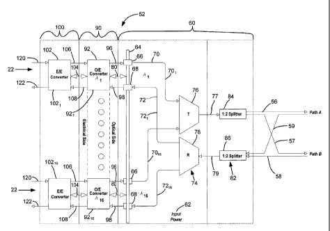
Referring now to Fig. 3, WDM 52 includes circuitry for converting
between native protocol media signals on channels 22 and the combined
multiplexed
optical signals on pathways 56, 57, 58, 59. WDM 52 includes
multiplexing/demultiplexing circuitry 60, hereinafter referred to as mux/demux
circuitry 60. Mux/demux circuitry 60 multiplexes the separate channels of
optical
signals into one signal for transmission to far end equipment. Mux/demux
circuitry
60 also demultiplexes the one signal received from far end equipment into
separate
channels of optical signals. WDM 52 includes optical to electrical conversion
circuitry 90 which interfaces with mux/demux circuitry 60. WDM 52 further
includes electrical to electrical conversion circuitry 100 which interfaces
with
optical to electrical conversion circuitry 90. The conversion circuitry 90,
100
converts between native protocol media circuitry and the optical signals
transmitted
by mux/demux circuitry 60. WDM 54 includes similar features, allowing for two-
way communication.
In the preferred embodiment, electrical to electrical conversion
circuitry 100 is removably connectable to mux/demux circuitry 60. Further, in
the
preferred embodiment, optical to electrical conversion circuitry 90 is
removably
connectable to mux/demux circuitry 60. In addition, it is preferred that
optical to
electrical conversion circuitry 90 is removably connectable to electrical to
electrical
conversion circuitry 100. It is anticipated that a variety of different
protocol media
signals may be desired for handling by mux/demux circuitry 60. Appropriate
conversion circuitry is selected for communicating between electrical to
electrical
conversion circuitry 100 and optical to electrical conversion circuitry 90,
and also
optical to electrical conversion circuitry 90 and mux/demux circuitry 60.
One result of the removable connections between components of
WDM 52 is that a variety of native protocol media signals can be handled with
a
reduced number of components. In particular, the electrical to electrical
conversion
circuitry 100 can be selected for the native protocol media signals which are
anticipated for WDM 52. The native protocol media signals can be converted
into a
common format signal such as NRZI digital format. An optical transceiver
associated with optical to electrical conversion circuitry 90 uses the NRZI
format
signal to modulate a laser associated with each channel. Each laser associated
with
optical to electrical conversion circuitry 90 operates at a different
wavelength.
4
CA 02558228 2006-08-31
WO 2005/086401
PCT/US2005/005968
Receivers associated with the optical to electrical conversion circuitry 90
receive
optical signals from mux/demux circuitry 60 and produce an NRZI format output
signal which is transmitted to the electrical to electrical conversion
circuitry 100.
By separating the optical to electrical conversion circuitry 90 from
the electrical to electrical conversion circuitry 100, different grades of
optical
devices (i.e., data rates, launch power, and wavelength) can be employed as
desired.
Therefore, in low end applications like DS3, 0C3, 10/100 M b/s Ethernet, lower
cost components can be used.
Mux/demux circuitry 60 includes a power input port 62 which
provides electrical power to a backplane 64. Backplane 64 can be constructed
from
a circuit board including appropriate circuit paths to link power from input
power 62
to each 0/E converter card 92. Backplane 64 includes optical couplers or
interfaces
66, 68 (such as adapters) for each 0/E converter card 92. Optical interfaces
66, 68
communicate through optical signal pathways 70, 72 to the multiplexer element
74
including multiplexer 76 or demultiplexer 78. From multiplexer 76 and
demultiplexer 78, one by two splitters 84, 86 are provided at splitter
circuitry 82 for
creating the dual optical pathways. Optical pathways 77, 79 link multiplexer
76, and
demultiplexer 78 to the respective splitters 84, 86. Preferably, optical
pathways 36,
38, 56, 57, 58, 59 are single mode optical pathways.
Each 0/E converter module or card 92 includes an optical link 96, 98
(such as connectors) for linking to optical interfaces 66, 68 of backplane 64.
An
electrical interface 80 provides for an electrical link from backplane 64 to
each 0/E
converter card 92, such as for any necessary power needed by each 0/E
converter
card 92. Also, electrical interface 80 can link control signals handled by
backplane
64 and communicated to each 0/E converter card 92.
Each E/E converter module or card 102 includes an electrical link
106, 108 for communicating electrical signals with each 0/E converter card 92
which are then converted into optical signals for transmission through
mux/demux
circuitry 60. Each E/E converter card 102 includes pathways 120, 122 for
communicating native protocol media signals on channels 22. An electrical link
104
connects between each E/E converter card 102 and the mated 0/E converter cards
92
for conveying any power needed by E/E converter cards 102, and for any control
signals to be communicated to the E/E converter cards 102.
5
CA 02558228 2006-08-31
WO 2005/086401
PCT/US2005/005968
Referring now to Fig. 4, backplane 64 is shown as including a card
edge connector 130 which connects to an edge contact 132 of 0/E converter card
92.
Together card edge connector 130 and edge contact 132 form the electrical link
80
of Fig. 3. Fiber optic connectors 134, 136 connect to optical interfaces 66,
68 of
back plane 64 wherein 0/E converter card 92 is connectable and disconnectable
with
backplane 64, as desired. 0/E converter card 92 includes a circuit board 140
including circuitry 142 for converting electrical signals from E/E converter
card 102
into optical signals for transmission at fiber optic connectors 134, 136. For
example,
DFB lasers are used on 0/E converter cards 92. Circuitry 142 of circuit board
140
further includes circuit pathways and elements for control and for converting
any
necessary power needed on 0/E converter card 92 for signal conversion. Also,
circuit pathways and elements are provided on circuit board 140 for linking
edge
contact 132 with card edge connector 144.
Card edge connector 144 on 0/E converter card 92 links to E/E
converter card 102 by connecting to an edge contact 148 on E/E converter card
102.
E/E converter card 102 includes one or more connectors 124 for connecting to
native
protocol media signals. E/E converter card 102 includes a circuit board 150
including circuitry 152 for converting signals from the native protocol media
format
into the common format, such as NRZI, between connectors 124 and edge contact
148. In the present system, it is anticipated that native protocol media
signals
include coaxial and twisted pair (shielded and unshielded). Also, it is
anticipated
that native protocol media signals include optical signals, such as multimode.
Circuitry 152 of circuit board 150 also includes circuit pathways and elements
for
power conversion for use in signal conversion between connectors 124 and edge
contact 148. Also, circuit pathways and elements are provided on circuit board
150
for receipt and processing of control signals received from backplane 64.
Referring now to Fig. 5, two optical to electrical converter cards 92
are shown removed from a chassis construction 270. Each converter card 92
operates at a different wavelength. Chassis construction 270 includes a
housing 280
for holding the circuit cards and components of system 10. Housing 280
includes an
open front 282 and internal guides 284 for guiding the circuit cards. Adjacent
to a
back 286 of chassis construction 270 is backplane 64. Chassis construction 270
can
be rack mounted or mounted to other system cabinets or frames.
6
CA 02558228 2006-08-31
WO 2005/086401
PCT/US2005/005968
Both optical to electrical converter cards 92 slide into open front 282
of chassis construction 270. A rear end 94 of each optical to electrical
converter
card 92 includes edge contact 132 and fiber optic connectors 134, 136 for
interfacing
with perpendicularly arranged backplane 64. At a front end 95 of optical to
electrical converter card 92, card edge connector 144 is positioned for
interfacing
with electrical to electrical converter card 102 arranged in a parallel
manner.
Adjacent to a back end 104 of E/E converter card 102 edge contact 148 is
positioned
for interfacing with card edge connector 144. At a front end 105 of E/E
converter
card 102 is positioned connectors 124. When both 0/E converter card 92 and E/E
converter card 102 are fully inserted into chassis construction 270,
connectors 124
are presented along a front face 288 of chassis construction 270 and are
linked with
backplane 64 for signal transmission to other system components, including a
far
end WDM 54.
Fig. 5 illustrates a second embodiment of an E/E converter card 190
for use in handling signals of a different native protocol format. Connectors
124 of
E/E converter card 102 are coaxial, such as for handling coaxial signals or
HDTV
signals. E/E converter card 190 includes a front port 252 for connecting to
twisted
pair cables. Specifically, port 252 is constructed as an RJ style jack.
Circuitry on
board 250 links port 252 with edge contact 148.
Chassis construction 270 further includes a CPU card 300 with ports
304, 306, 308 for connecting to other system components. CPU card 300 includes
a
rear interface (not shown on Fig. 5) similar to edge contact 148 for
connecting to
backplane 64, such as with a card edge connector, like card edge connector
130.
CPU control signals are linked from CPU card 300 to each 0/E converter card 92
and E/E converter card 102 through backplane 64. CPU card 300 sends command
and control signals to each 0/E converter card 92, and each E/E converter card
102.
Also CPU card 300 can communicate with other system components including far
end WDM's 54.
Fig. 5 also shows a splitter card 350 which shows four optical ports
352, 354, 356, 358. The optical ports provide for the dual path optical signal
transmission to other system components, including a far end WDM 54. A rear of
splitter card 350 includes optical connections to circuit paths 56, 57, 58,
59, noted
above.
7
CA 02558228 2006-08-31
WO 2005/086401
PCT/US2005/005968
Referring now to Fig. 6, an alternative arrangement for a WDM 452
is shown. A similar backplane 464 is provided as noted above for WDM 52
including a card edge connector 530 and optical interfaces 66, 68. Similar
mux/demux circuitry 60 is provided for multiplexing and demultiplexing the
optical
signals for transmission to far end equipment. One difference with WDM 452 is
that
the input and output native protocol signals are through backplane 464,
instead of
adjacent to a front of WDM 452. E/E converter card 502 receives input signals
and
provides output signals for the native protocol format at native pathways 560,
562.
Distal ends define connectors 564, 566 and are connected to cables, such as 75
ohm
coaxial cables. Proximal ends 568, 570 define interface structure for mating
with
coaxial connectors 572, 574 of E/E converter card 502. Converter card 502 also
communicates with backplane 464 through an edge contact 532 received in card
edge connector 530. Any power needed for signal conversion on E/E converter
card
502 is provided through edge contact 532. Also, all control signals can also
be
processed through edge contact 532. E/E converter card 502 includes circuitry
550
for converting native protocol media signals into common signal format, such
as
NRZI format. Also, circuitry 550 includes any necessary links between edge
contact
532, and 0/E converter card 492, such as for power or control. E/E converter
card
502 includes an edge contact 548 for interfacing with the card edge connector
544 of
0/E converter card 492. 0/E converter card 498 includes conversion circuitry
498
for converting between common format signals and optical signals for
communicating with mux/demux circuitry 60. Fiber optic connectors 534, 536
interface with optical interfaces 66, 68 to optically connect to mux/demux
circuitry
60.
E/E converter card 502 includes access circuitry 580 for test or patch
access to the native protocol media signals. Such test access may include a
splitter
function where a portion of the signal is tapped off, such for monitoring. In
the case
of patch access, switches can be included, such as switching jacks, for
completely
removing connectors 572, 574 from the circuit paths. In this manner, signals
to or
from card 502 can alternatively be to a second location, instead of through
backplane 464.
The electrical interface 80 preferably includes an identification
feature which will identify a code on 0/E converter card 92 so that only an
8
CA 02558228 2006-08-31
WO 2005/086401
PCT/US2005/005968
appropriate wavelength output will be accepted for each interface 80. For
example,
a bit position could be hardwired on to the card edge connection circuitry. In
this
manner, only the desired 0/E converter card 92 with the desired wavelength for
the
overall system can be inserted and used. CPU card 300 can be employed to run
queries of each card 92. With such a system, cards 92 at the wrong wavelength
cannot be inserted into backplane 64 and used to cause system communication
failures.
Preferably, power input port 62 is Telco power, and any different
power needed by either 0/E converter cards 92 or E/E converter cards 102 can
be
accomplished through isolated power converters on each of the cards.
While WDM 52 is shown as including 16 channels of signals (16
wavelengths), greater or fewer channels can be handled by appropriately
selected
conversion circuitry and mux/demux circuitry. In one preferred implementation,
an
18 channel system can be provided wherein at least one channel is reserved for
interconnecting local and remote CPUs for management and control. WDM's 52, 54
are considered CWDM's in the preferred embodiment. There would be a 20 nm
optical separation between each laser. Systems with 2, 4, 8, 16, 20, and 48+
channels can be implemented with appropriate 0/E cards 92.
Path protection is accomplished by using a one by two splitter on the
output of the WDM mux/demux circuitry 60. A one by two splitter will typically
reduce the power level on each output fiber by 50%. Preferably, each laser
associated with the 0/E converter cards has a sufficiently high optical launch
power
that allows this system to use splitters for path protection instead of
optical switches.
This has particular application for short haul applications.
With the above systems, a variety of native protocol media signal
formats can be supported using an appropriately selected E/E converter card
102.
Optical inputs can also be supported wherein the E/E converter card 102
converts
the optical signal into an electrical signal, such as in the common format
signal,
wherein that signal is then converted back into an appropriate optical signal
in the
0/E converter card 92 for communication with the mux/demux circuitry 60. By
splitting the converting functions between 0/E cards and E/E cards, the number
of
line cards needed to populate a given chassis is reduced.
9
CA 02558228 2013-03-27
, =
The E/E converter cards 102 and the 0/E converter cards 92 can be
added over time as systems grow. A chassis construction 270 can be sold
partially
populated, and then as system needs increase, additional cards can be added.
Also,
upgrades can be easily added with only replacing one of the 0/E converter
cards 92
or the E/E converter cards 102, depending on the upgraded elements. In the
case of
field replaceability, only that component needing replacement needs to be
removed
and replaced. The modular 0/E convert cards allow for lower cost optics to be
used
for less demanding applications (i.e., less than 155 Mb/s).
Systems 10, 12 are protocol independent. E/E converter cards 102
are selected for the given native protocol. 0/E converter cards 92 are
provided with
the desired laser and optical performance. Such systems are advantageous
during
manufacture and during maintenance and upkeep over time.
While preferred systems include both transmit and receive pathways,
other systems may only need transmit or receive on each respective near and
far end
WDM's 52, 54. For example, one way video does not need both transmit and
receive functions at each end. In this system, the corresponding multiplexer
or
demultiplexer components and pathways can be removed to further save cost.
The above specification, examples and data provide a complete
description of the manufacture and use of the composition of the invention.