Note: Descriptions are shown in the official language in which they were submitted.
CA 02558253 2007-03-02
WO 2005/091101 PCT/US2005/006852
DYNAMIC REACTIVE COMPENSATION SYSTEM AND METHOD
BACKGROUND OF THE INVENTION
This invention relates to electric power utility networks including generating
systems, transmission systems, and distribution systems serving loads.
To remain competitive, electrical utility companies continually strive to
improve
system operation and reliability while reducing costs. To meet these
challenges, the
utility companies are developing techniques for increasing the life of
installed equipment,
as well as, diagnosing and monitoring their utility networks. Developing these
techniques is becoming increasingly important as the size and demands made on
the
utility power grid continue to increase. A utility power grid is generally
considered to
include both transmission line and distribution line networks for carrying
voltages greater
than and less than about 35 kV, respectively.
Voltage instability on the utility power grid is a critical problem for the
utility
industry. In particular, when a fault occurs on the transmission grid,
momentary voltage
depressions are experienced, which may result in voltage collapse or voltage
instability
on the grid. In general, such a fault appears as an extremely large load
materializing
instantly on the transmission system. In response to the appearance of this
very large
load, the transmission system attempts to deliver a very large current to the
load (the
fault). Detector circuits associated with circuit breakers on the transmission
system
detect the overcurrent situation immediately (i.e., within a few
milliseconds.) Activation
signals from the utility protective relays are sent to the circuit breaker
which opens the
circuit. The mechanical nature of the circuit breakers generally requires 3-6
cycles (i.e.,
up to 100 msecs) to open. When the breakers open, the fault is cleared.
However,
opening of the breakers triggers a sequence of events, which in the extreme
can cause that
portion of the transmission and distribution system to collapse. Specifically,
when the
breakers open, the voltage is still low (i.e., almost zero) and, because a
portion of the
transmission system has in effect been removed, the impedance of the system
dramatically increases causing the appearance of an artificially high load. In
this state the
CA 02558253 2007-03-02
WO 2005/091101 PCT/US2005/006852
voltage is depressed and the current serving the load sharply increases. The
sharp
increase in the current generates enormous losses in the transmission and
distribution
systems. In some cases, because the load and impedance are high, the voltage
on the grid
may not return to normal, causing long-term voltage depression and the
possible voltage
collapse of the entire system. The potential for these voltage instability
problems are
further exacerbated as load requirements on the grid increase.
One approach for addressing this problem is to construct additional
transmission
lines, thereby negating the effects of the high losses and sharp increase in
current flow
caused by the opening of the breaker. However, providing such additional lines
is
expensive and in certain settings extremely difficult.
Various equipment and device solutions have also been developed to address
these voltage instability and collapse problems, such as SVCs and STATCOMs as
described in greater detail below. In general, such devices remove the losses
contributing
to the huge increase in current by temporarily injecting power into the
system. These
losses can be both resistive as well as reactive. To understand the difference
between
resistive and reactive losses, note that the general expression for average
power (when
waves of voltage and current are sinusoidal), is V. "' cos 0, where Vrõ and
I,,, represent the
peak voltage and current, respectively. Since the maximum value of a sine wave
divided by
the square root of 2 is the effective value, the equation for average power
may be written as:
P= V. L" cos B= VI cos B
-,F2 -52
When V is in volts and I is in amperes, the power is expressed in watts. The
instantaneous
power is:
V. L V,,, L
p 2 cos B- 2 cos B cos 2wz1 + V~" sin 9 sin 2wz
The first two terms of the right side of this equation represent instantaneous
real power.
When 2coi is an odd multiple of ir, the value of the real power is
2Võh,
cos B= 2VI cos B
2
When 2coi is a multiple of 27r, the real power is 0. Hence real power in a
single-phase
2
CA 02558253 2007-03-02
WO 2005/091101 PCT/US2005/006852
circuit fluctuates between 0 and 2VI cosTc and has an average value of VI cos
7t. The third
term of the right-hand member of the equation represents what is referred to
as
instantaneous reactive power, or, preferably, instantaneous reactive volt-
amperes. Its
equation is
px = r ~I"' sin 8 sin 2wz
In, V. I,,,
Thus instantaneous reactive volt-amperes fluctuate between + V. 2 sin ~n and -
2 sin 7t.
Whereas the average value of the instantaneous reactive volt-amperes is zero;
the maximum
value is V2I"' sin 7t. This is the value referred to when reactive volt-
amperes are considered.
Hence,
Px= V. - Im -sin6=VIsin6
,,~F2 V-2
Reactive volt-amperes are expressed in VARs; a term coined from the first
letters of
the words "volt amperes reactive". Reactive volt-amperes considered over a
period of time
represent oscillations of energy between the source and the load. Their
function is to supply
the energy for magnetic fields and charging condensers, and to transfer this
energy back to
the source when the magnetic field collapses or when the condenser discharges.
Although
reactive volt-amperes, as such, require no average energy input to the
generators, they do
necessitate a certain amount of generator volt-ampere capacity and thereby
limit the
available power output of the generators. Reactive power is due to quadrature
components
of voltage and current and as such represents no average power. These
additional losses,
which increase the required total real power, are generally supplied by an
average energy
input to the generators.
Historically, power utilities address severe voltage stability and control
issues on
transmission and distribution grids with traditional Static VAR Compensator
(SVC) and
Static Synchronous Compensator (STATCOM) solutions. A STATCOM is a form of an
SVC that uses power electronics (e.g., a voltage sourced inverter) to generate
the VARs.
Referring to Fig. 1, an SVC 100 is shown to include a phase-controlled TCR
(Thyristor Controlled Reactor) 102 and a set of TSCs (Thyristor Controlled
Capacitors)
3
CA 02558253 2007-03-02
WO 2005/091101 PCT/US2005/006852
104 connected on the secondary side of a coupling transformer 106. SVC 100
provides
reactive power from both TCR 102 and TSCs 104 when a fault is experienced on
the
utility grid. In particular, TCR 102 and TSCs 104 are connected to transformer
via a
medium voltage line 108 (12-20 KV). The primary side of transformer 106 is
connected
to the high voltage transmission line (e.g., > 35 KV) 110. In normal
operation, a TSC
104 is in the "on" condition all of the time while a TCR 102 is gated on at a
specific
phase angle every half-line-cycle to cancel out a portion of the capacitive
VAR injection.
For small phase angles, the conduction time and therefore the inductive VARs
is small.
For large phase angle approaching 180 degrees, the TCR 102 is essentially "on"
the
entire half-cycle and more of the capacitive VARs are canceled. . A controller
(not
shown) provides control signals to the TSCs 104 and gating signals to the TCR
102 to
allow for infinite control of VAR output from 0-100% depending on system need.
Switching of TCR 102 and TSCs 104 occurs very quickly (e.g., within one-half
line
cycle) using thyristor switches 116. The TCR is sized to provide maximum
lagging
VARs, while the TSCs may be of the same or different sizes (e.g., 25-100 MVAR)
to
incrementally introduce capacitive VARs to the system. Thus, TCR 102 serves as
a
variable VAR compensation device while TSCs 104 serve as fixed but
incrementally
added/subtracted VAR compensation devices.
In operation, SVC system 100 regulates voltage at its terminal by controlling
the
amount of reactive power injected into or absorbed from the utility power
system. When
system voltage is low, SVC 100 generates reactive power (SVC capacitive). When
system voltage is high, it absorbs reactive power (SVC inductive). More
specifically,
SVC 100 rapidly delivers the reactive power to shift the power angle, thereby
raising or
lowering the voltage on the network. SVC 100 continuously shifts the power
angle in
response to dynamic power swings on the transmission network due to changing
system
conditions.
SVC system 100 can also include smaller harmonic filter capacitors 112 (e.g.
each
10-30 MVARs) that are always "on" and filter out higher harmonics (e.g., 5`"
and 7t"
order harmonics as tuned by inductors 113 in series with capacitors 112)
generated by the
4
CA 02558253 2007-03-02
WO 2005/091101 PCT/US2005/006852
natural action of the thyristors. SVC system 100 can also be used in
conjunction with
mechanically-switched capacitors 114 for voltage regulation.
Such static VAR compensators provide capacitive reactance for several reasons.
First, utility power systems, particularly at the transmission level, are
primarily inductive,
due to the length of transmission lines and the presence of numerous
transformers.
Second, many of the largest loads connected to the utility power system are
typically
inductive. Large motors used, for example, in lumber mills, rock crushing
plants, steel
mills, and to drive pumps, shift the power factor of the system away from the
desired
unity level, thereby decreasing the efficiency of the power system. By
selecting the
proper amount of capacitance and connection location, the capacitor banks can
provide a
level of control of the line voltage, power factor, or volt-ampere-reactive
(VAR) power.
Because most inductive loads operate intermittently and cyclically, the
correct
compensation is generally applied selectively in response to the varying
reactive load on
the system.
SVCs and STATCOM systems have the attribute of being capable of providing
rapidly changing VARs needed to regulate voltage and quickly drive post-
contingency
voltages to acceptable levels. The timeframe required for the solution's
response is on
the order of a few line-cycles of AC power (one line cycle is 16.7mS for 60Hz
AC power
systems) even though it is capable of responding on a sub-cycle basis.
However, the
primary disadvantage of SVC and STATCOM systems is their high cost.
SUMMARY OF THE INVENTION
The invention features a system and approach for providing dynamic reactive
compensation to utility transmission and distribution grids. Reactive
compensation is
accomplished by injecting capacitive or inductive reactive current in shunt
with a utility
power network.
In one aspect of the invention, a system for connection to a utility power
network
includes a reactive power compensation device coupled to the network and
configured to
transfer reactive power between the utility power network and the reactive
power
compensation device; a capacitor system configured to transfer capacitive
reactive power
5
CA 02558253 2007-03-02
WO 2005/091101 PCT/US2005/006852
between the utility power network and the capacitor system; an electro-
mechanical
switch for connecting and disconnecting the capacitor system to the utility
power
network; an interface associated with the electro-mechanical switch; a
controller
configured to provide control signals for controlling the electro-mechanical
switch; and a
communication channel for coupling the controller to the interface associated
with the
electro-mechanical switch. The electro-mechanical switch, interface,
controller, and
communication channel together are configured to connect or disconnect the
capacitor
system from the utility power network within about three line cycles or less
of the
nominal voltage frequency when a fault condition is detected on the utility
power
network.
Embodiments of these aspects of the invention may include one or more of the
following features. The electro-mechanical switch, interface, controller, and
communication channel together are configured to connect or disconnect the
capacitor
system from the utility power network in less than about 80 msecs and
preferably less
than about 50 msecs from the time the fault condition is detected on the
utility power
network.
The communication channel is a fiber optic channel. The system further
includes
a number of capacitor systems, each configured to transfer capacitive power
between the
utility power network and a respective one of the capacitor systems. Each of
the
capacitor systems is coupled to a corresponding electro-mechanical switch, the
controller
being configured to operate each capacitor system using a corresponding
electro-
mechanical switch. In operation and following a predetermined time period, the
controller monitors whether to activate or deactivate an additional one of the
capacitor
systems. The controller is configured to initially activate a predetermined
subset of the
capacitor systems.
The reactive power compensation device (e.g., an inverter) is configured to
provide voltage regulation and prevent voltage collapse by quickly providing
reactive
power to the utility power network so as to rebuild system voltage back to
within 10% of
the nominal voltage within two seconds, preferably within one second. The
reactive
power compensation device may include an array of inverters.
6
CA 02558253 2007-03-02
WO 2005/091101 PCT/US2005/006852
The system further includes at least one mechanically-switched capacitor or
reactor,
each configured to transfer capacitive or inductive power to the utility power
network in
response to a signal from the controller.
The controller is configured to, in response to the need to connect at least
one
capacitor system to the utility power network, activate the reactive power
compensation
device and, substantially simultaneously, causes the at least one capacitor
system to be
connected to the utility power network.
In another aspect of the invention, a method for stabilizing a utility power
network
includes the following steps. A reactive power compensation device is
electrically coupled
to the network and is configured to transfer reactive power between the
utility power network
and the reactive power compensation device. At least one capacitor system
including an
electro-mechanical switch is electrically coupled to the network and is
configured to transfer
capacitive power between the utility power network and the at least one
capacitor system. A
fault condition is detected on the utility power network. In response to
detecting the fault
condition, at least one electro-mechanical switch is operated within about
three line cycles or
less of the nominal voltage frequency.
Embodiments of this aspect of the invention may include one or more of the
following
features. A controller is coupled to the electro-mechanical switch with a
fiber optic
communication channel. A plurality of capacitor systems is coupled to the
utility power
network, each associated with a corresponding electromechanical switch and
each configured
to transfer capacitive power between the utility power network and a
respective one of the
plurality of capacitor systems. A controller monitors whether to activate an
additional one or
a preset of the capacitor systems bank or deactivate one or a preset of the
capacitor systems.
The controller controls the reactive power compensation device to quickly
provide
reactive power to the utility power network so as to boost voltage to 0.90
P.U. of the nominal
line voltage within two seconds, preferably within one second. The reactive
power
compensation device comprises at least one inverter or an array of inverters.
In response to the need to connect the at least one capacitor system to the
utility
power network, the reactive power compensation device is activated and,
substantially
simultaneously, the at least one capacitor system is connected to the utility
power network.
Prior to detecting a fault condition on the utility power network, the
reactive power
compensation device is controlled to provide voltage regulation of the utility
power network.
7
CA 02558253 2007-03-02
WO 2005/091101 PCT/US2005/006852
Controlling the reactive power compensation to provide voltage regulation
includes
deactivating at least one of the capacitor systems if the nominal voltage on
the utility power
network is greater than a predetermined upper threshold (e.g., 1.04 P.U.).
Controlling the
reactive power compensation to provide voltage regulation also includes
activating at least
one of the capacitor systems if the nominal voltage on the utility power
network is less than a
predetermined lower threshold (e.g., 1.0 P.U.).
Deactivating the reactive power compensation device if bucking VARS are
required
and if a predetermined capacitor timing period (e.g., in a range between one
second and
several minutes) has expired. The capacitor timing period is dependent on the
reactive power
output of the reactive power compensation device. Activating the reactive
power
compensation device if boosting VARS are required and if a predetermined
capacitor timing
period has expired. If the nominal voltage on the utility power network is
less than a
predetermined fast control threshold (e.g., > 10% of the nominal voltage): 1)
activating at
least one of the plurality of capacitor systems; and 2) controlling the
reactive power
compensation device to increase VAR injection from the reactive power
compensation
device.
The method further includes controlling the reactive power compensation device
to
increase VAR injection from the reactive power compensation device if boosting
VARs are
required, controlling the reactive power compensation device to decrease VAR
injection
from the reactive power compensation device if boosting VARs are not required
and if the
nominal voltage is less than a predetermined overvoltage threshold (e.g., 5 %
of the nominal
voltage); and controlling the reactive power compensation device to increase
VAR injection
from the reactive power compensation device if boosting VARs are not required
and if the
nominal voltage is greater than the predetermined overvoltage threshold.
The method further includes deactivating at least one of the capacitor systems
if the
nominal voltage is greater than a fast capacitor removal threshold (e.g., >5%
of the nominal
voltage); and activating at least one of the capacitor systems if the nominal
voltage is less
than the predetermined fast control threshold.
The system and method are capable of attenuating rapid voltage variations and
for
providing post-fault voltage support to mitigate any tendency for voltage
collapse. In
addition to acting as a fast transient voltage support device, the system is
also capable of
regulating voltage at a point on the transmission or distribution grid and
minimizing transients
8
CA 02558253 2007-03-02
WO 2005/091101 PCT/US2005/006852
imposed on the fundamental waveform of a normal voltage carried on a utility
power network
when a reactive power source (e.g., capacitor bank) is connected to the
utility power network.
By integrating the dynamic VAR output of the reactive power compensation
device (e.g.,
inverters) with very fast (e.g., 24msecs) mechanically switched capacitor and
reactor banks,
the system becomes a very economical alternative to SVC's and equally
effective at solving
common transmission grid problems such as voltage instability and voltage
regulation.
SVC's and STATCOMs are faster than necessary to solve these problems and are
very
costly. Conventional mechanically switched reactive devices, while of
acceptable speed
(>100mS) for voltage regulation, are too slow to solve voltage instability.
The invention
addresses the speed limitations of conventional mechanical switches and uses
them provide
the bulk of the reactive power while the reactive power compensation device
(e.g., inverters)
provides a small (10-25%) but overly fast amount of reactive power. The
reactive power
compensation device generally only moves the voltage a few percent at rated
output and thus
the opportunity for unstable behavior and/or oscillations is significantly
reduced. Thus,
although the system of the invention has the same range as an SVC, the control
of capacitors
for slow control makes it look much smaller in the dynamic sense and hence
precludes many
of the instability problems. Further, because the cost of the system is about
25% less then a
comparably sized SVC, the invention provides an economic alternative to
STATCOM -
based and SVC- based systems. The invention also uses electro-mechanical
switches that are
considerably less expensive than conventional thyristor switches used in an
SVC.
These and other features and advantages of the invention will be apparent from
the
following description of a presently preferred embodiment and the claims.
BRIEF DESCRIPTION OF THE DRAWINGS
Fig. 1 is a block diagram of a conventional SVC system.
Fig. 2 is a block diagram of a dynamic voltage system including D-VAR
statcoms
and fast-switched capacitor banks.
Fig. 3 is a block diagram of the D-VAR statcoms of the dynamic voltage system
of Fig. 2.
Fig. 4 is a block diagram of a fast-switched capacitor bank and the
communication
link of Fig. 2.
9
CA 02558253 2007-03-02
WO 2005/091101 PCT/US2005/006852
Fig. 5 is a graph illustrating the relationship between VAR output as a
function of
time for the dynamic voltage system of Fig. 2.
Fig. 6 is a flow diagram illustrating the general steps for operating the
dynamic
voltage system.
Figs. 7A-7C are flow diagrams illustrating the general steps for operating the
dynamic voltage system in slow mode.
Figs. 8A-8C are flow diagrams illustrating the general steps for operating the
dynamic voltage system in fast mode.
DETAILED DESCRIPTION
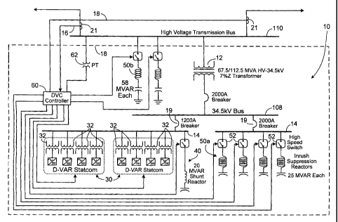
Referring to Fig. 2, a dynamic voltage system 10 is shown connected in shunt
with a
transmission line 110 of a utility power network via a first transformer 12,
which steps down the
higher voltage (e.g., greater than 35 kV carried on transmission line 110 to a
lower voltage, here
34.5 kV, of a medium voltage bus 108. Dynamic voltage system 10 includes, in
this
embodiment, a pair of D-VARO statcom systems 30, each of which are coupled to
an internal
bus 14 with summing transformers 32. D-VARO statcom systems 30 are available
from
American Superconductor Corporation, Westboro, MA. Because each D-VARO statcom
system 30 has a nominal 480VAC output, two stages of transformation
(transformers 12 and
32) to interface to a high voltage transmission system are used.
Dynamic voltage system 10 also includes a shunt reactor 40 and, in this
embodiment,
four capacitor banks 50a, each coupled to internal bus 14. Shunt reactor 40
provides negative
(inductive) VARs over and above those provided by D-VARO statcom systems 30
and
capacitor banks 50a are capable of generating 20 MVAR and 25 MVARs of
reactance per
bank, respectively. Shunt reactor 40 and capacitor banks 50a are coupled
through internal bus
14 to medium voltage bus 108 through appropriately sized circuit breakers 19.
Dynamic
voltage system 10 further includes, in this embodiment, a pair of capacitor
banks 50b, each
coupled to transmission line 110. Capacitor banks 50b are capable of
generating 50 MVARs of
reactance per bank, about twice as much MVAR capacity as capacitor banks 50a.
Because
capacitor banks 50b are connected directly to the higher voltage transmission
bus 110 they
provide a more cost-effective way of injecting a greater amount of capacitive
reactance to the
utility power network in the event of a fault.
CA 02558253 2007-03-02
WO 2005/091101 PCT/US2005/006852
D-VAR statcoms 30, reactor 40 and capacitor banks 50a, 50b are all controlled
by a
DVC controller 60 in response to voltage fluctuations sensed over signal lines
18, which are
connected to the utility power network. In this embodiment, capacitor banks
50a, 50b may be
used for voltage regulation in conjunction with "slower" mechanically-switched
capacitor
(MSCs) banks (i.e., switching times >6 line cycles). For example, capacitor
banks 114, as
shown in Fig. 1, represent the type of mechanically-switched capacitors which
may or may
not already be provided for voltage regulation by utility companies at a given
substation.
Utility MSCs can be controlled for long-term voltage regulation through a
supervisory
control and data acquisition (SCADA) interface. However, mechanically-switched
capacitors 114 of the type shown in Fig. 1 are too slow for preventing voltage
collapse.
In general, and as will be described in greater detail below, D-VAR statcom
systems
30 generate the dynamic, variable VAR component of the solution while
capacitor banks 50a,
50b provide the incrementally or stepped capacitive VAR component of the
system and shunt
reactor 40 provides the incrementally or stepped inductive VAR component of
the system. It
should be appreciated that for purposes of clarity, only one of the three
phases of the power
system are shown. Also, certain components (e.g., fuses, protective relays,
breakers) typically
used in utility power systems are not shown in Fig. 2.
Referring to Fig. 3, each D-VAR statcom system 30 which, in this example,
includes
thirty two 250 kVA inverter modules 36 whose outputs are combined on the
medium-voltage
side of the power transformers to yield the desired system performance.
Depending on the
implementation, suitable inverter modules include Power ModuleTM PM250, and
Power
ModuleTM PM1000, both of which are available from American Superconductor
Corporation,
Westboro, MA. The inverter modules 36 are coupled to the secondary side of
summing
transformers 32 through circuit breakers 34.
Referring again to Fig. 2 and Fig. 4, to effectively address fault conditions
sensed
by controller 60, capacitor banks 50a and 50b, and reactor 40 must be capable
of being added
and removed as fast as possible to the intermediate (distribution voltage)
and/or transmission
voltage bus. Traditional circuit breakers, motor operated switches, or fast
switches
controlled through conventional utility signaling means are too slow. To
overcome this
problem, direct communication from controller 60 to high speed vacuum switches
52 are
used to provide necessary trip (open) and close timing.
11
CA 02558253 2007-03-02
WO 2005/091101 PCT/US2005/006852
In particular, and as shown in Fig. 4, each capacitor bank 50a, 50b includes
one or
more capacitors 53, an inrush suppression reactor 57 and a vacuum switch 52.
Control
signals from controller 60 are received over a fiber optic communication line
54 and by a
digital interface 56 of vacuum switch 52. One example of a fiber optic
communication line
suitable for use is a molded cable having industry standard 62.5/125 micron
glass multimode
fiber with ST connectors. A capacitor switch having suitable trip and close
timing
characteristics is the VBU switch, manufactured by Joslyn Hi-Voltage
Corporation,
Cleveland, OH. The Joslyn VBU switch possess trip and close timing
characteristics of
about 24msecs or 29 msecs, respectively or 1.5 line cycles at 60 Hz. Each
capacitor bank
50a, 50b includes an inrush suppression reactor 57. Each inrush suppression
reactor 57 is
used to limit the "inrush" or current when an additional discharged capacitor
bank in parallel
is activated with a capacitor bank that has already been activated.
Exemplary characteristics of a capacitor switch 52 suitable for use in dynamic
voltage system 10 are shown below:
Switch Opening (per pole)
Direct Energy Voltage: 40VDC
Close Coil Resistance: 2 ohms
Trip Timing
- from solenoid energization to contact part 17 ms
- from contact part to full open 7 ms
- total opening time (solenoid energization to full open)
- Direct Energy 24 ms max.
- Capacitor Discharge (reference) 24ms max.
Switch Closing (per pole)
Capacitor Discharge Voltage 250 V
Discharge Capacitance 6500 mF
Close Timing (from solenoid energization to contact touch)
- Capacitor Discharge 28 ms max.
20 ms min.
Control Response Time
- Analog Controls 30 ms max.
- Digital Controls < 1 ms.
In a particular embodiment, the normal utility interface (Analog Controls) of
the
Joslyn VBU switch is bypassed so that communication of the trip (open) and
close signals
12
CA 02558253 2007-03-02
WO 2005/091101 PCT/US2005/006852
are provided directly to the switch trigger mechanism, thereby avoiding the
time delay
(30msec) associated with the conventional analog interface.
Referring again to Figs. 2 and 4, each switched capacitor bank 50a, 50b also
includes
a saturable reactor that is normally implemented in the form of a potential
transformer (PT)
59 having a secondary (not shown) which can be used for diagnostic purposes or
left open.
When the high speed switch is closed, AC voltage is present on capacitor 53 of
capacitor
banks 50a, 50b and PT 59. When AC voltage is present, capacitor 53 appears to
the PT like a
high impedance load. But when the capacitor switch 52 opens, trapped charge on
the
capacitor bank appears like a DC voltage to the PT. At a time typically less
than one AC
line-cycle (17mS) after the switch opens, the magnetic core of the PT will
saturate. Once
saturated, the PT's impedance drops several orders of magnitude and appears to
the capacitor
bank like a short circuit and quickly discharges the trapped charge within the
capacitor;
hence the name "Shorting PT". Quickly discharging the capacitor makes it
available to be
switched in by the DVC Controller as needed.
With respect to vacuum switches 52, communication signals "Open" and "Close"
carried on communication line 54 are commonly required for fault tolerance.
The "Status"
signal is optional but almost always present as standard practice. The status
signal can be
one of many signals. For example, in one embodiment, one signal indicates the
status of the
switch (open or closed) while a second signal indicates diagnostic information
("Ready"
versus "Fault"). In the preferred embodiment, both a status and fault signal
are sent back to
controller 60 at high speed. This way, if the controller 60 commands switch 52
to close but
the status indicates that it did not close, the controller can quickly command
a different
switch to close. Likewise, if the controller is about to command one switch to
close but that
switch is reporting a fault, the controller can command a different switch to
close instead.
Thus, overall functionality and effectiveness of the dynamic voltage system 10
is not
compromised in the event of a capacitor or high-speed switch failure.
D-VAR Statcom and Capacitor Control
The control of the D-VAR statcoms 30, reactor 40 and capacitor banks 50a, 50b
is
based on two different modes and time scales. The first time mode is based on
providing
long term regulation of the voltage on the utility power network while the
second time mode
is based on the occurrence of a significant fault on the high voltage
transmission line 110.
13
CA 02558253 2007-03-02
WO 2005/091101 PCT/US2005/006852
For all of the discussions that follow, approximate values for setpoints and
thresholds will be
given to facilitate the discussion. It should be appreciated that the user
parameters discussed
below can be modified depending on the particular application and conditions.
Further, with
reference to the adding or removing of capacitor banks, it is appreciated that
inductive
elements can also be added or removed, the net effect on the system voltage
being equivalent
from a slow steady control perspective.
In this context, the term `regulation' is meant to infer the slowly varying
control of
the voltage on the utility power network. The time scales in this context
being on the order
of seconds. On the other hand, a fault event requires much faster response
times (i.e., within
a few line cycles or less). Controller 60 distinguishes between a regulation
and a fault
condition by comparing the currently measured voltage to the long term average
(typically
between 0.1 and 10 seconds). If there is a drop in the voltage of greater than
0.10-0.15 PU of
the nominal voltage then the "fast" controls take over. Otherwise the system
ignores smaller
transients than this and responds in a voltage regulation mode. Each of these
two modes is
described in greater detail below and is understood to be one method of many
to achieve the
goal. The controller 60 typically receives a voltage signal from a Potential
Transformer (PT)
62 (Fig. 2) connected to bus 110.
Voltage regulation
The system has an adjustable band of acceptable voltage (e.g., from 1.00 to
1.04 PU).
So long as the measured voltage on the transmission line remains within this
band, controller
60 takes no action other than to compute a long term voltage average. If the
voltage drifts
slowly outside of these limits, controller 60 determines that the DVC statcoms
30 will need
to respond. Controller 60 sends control signals to D-VAR statcoms 30 to cause
dynamic
VARs to be injected into the network. Controller 60 uses a Proportional plus
Integral (PI)
control loop algorithm with a target set to prevent the voltage from drifting
outside the band.
As soon as D-VAR statcoms 30 start injecting dynamic VARs, a capacitor timer
is
initiated. If the voltage settles to a value within the band on its own, the D-
VAR statcom
simply ramps back down. However, if the utility power network continues to
require
30 dynamic VARs for a time period as long or longer than the time needed for
the capacitor
timer to expire, then controller 60 will request that a capacitor be switched
on or off
depending on which limit is reached, low or high. Because there can be a very
large
14
CA 02558253 2007-03-02
WO 2005/091101 PCT/US2005/006852
variability in the delay between the request for a capacitor bank to be
switched and the actual
switching itself, the system does not "know" when the transient will occur.
For example, some of the capacitor banks used for regulation may be located
miles
away and accessed via a SCADA system while others are local and triggered with
the high
speed switches. Therefore, after requesting a capacitor bank 50a, 50b, the
system continues
to hold the voltage at its target level. When a capacitor bank 50a, 50b is
finally switched, the
transient will move the voltage toward the center of the band. Since the
dynamic voltage
system 10 is attempting to hold the edge, this will initially look like a
negative error which
will be compensated for by the PI control algorithm. As a result the dynamic
VAR output of
the D-VAR statcoms 30 will be quickly ramped off. This reduces the net
transient of the
capacitor switch. At that point, the voltage will be within the band and the D-
VAR
statcoms will return to monitoring and wait for the voltage to again exceed
one of the band
edges.
Slow capacitor switching profile
The primary control of capacitor banks 50a, 50b by controller 60 is based on
the
output of inverters 36 of D-VAR statcoms 30 either by MVARs or, equivalently,
by the
current required in the inverters. Ideally, capacitor banks 50a are sized to
accommodate the full
range of voltage regulation and capacitor banks 50b are sized to provide the
larger VARs
required to prevent voltage collapse in conjunction with capacitor banks 50a.
Generally, if the
dynamic voltage system 10 requires significant capacitive / boosting MVARs for
an extended
period, it will want to replace these dynamic VARs with static VARs by
switching in a capacitor
bank. Conversely, inductive VARs being used to hold the voltage down will
eventually call for
the removal of a capacitor bank. If all of the capacitors have been previously
removed,
inductive VARs from D-VAR statcoms 30 will be used to hold down the voltage
until
reactor 40 is switched on. It is further appreciated that generally a higher
dynamic VAR output
will call for a capacitor switching event sooner than an incrementally lesser
VAR output, and
that there are predetermined minimum and maximum capacitor switching intervals
and
corresponding VAR levels.
Referring to Fig. 5, for continuously maintained current outputs of magnitude
IZ
boosting or I4 bucking, a capacitor switch operation will be called for if
such an operation is
possible ( i.e., a capacitor is available to be switched. In such situations,
capacitor switching
CA 02558253 2007-03-02
WO 2005/091101 PCT/US2005/006852
will occur after the output is being commanded for T2 or T4 seconds, (points
70, 72)
respectively. Greater current outputs will result in capacitor bank switching
transactions
occurring sooner, limited by the minimum switching times T, or T3. Output
magnitudes
greater than I1 boosting or 13 bucking cause capacitor switching at the same
minimum
switching times. The output-switching time profiles in between the minimum and
maximum
switching times are linear.
Current outputs of magnitudes less than I2 boosting or 14 bucking will not
result in
capacitor switching. Furthermore, the counters that implement the capacitor
switching
profiles reset when commanded currents drift back into the non-switching zone.
All of the
time (T) and current (I) values above can be preset. Aside from the limitation
that T2 > T,
and T4 > T3, there are few absolute restrictions. For reasons of numerical
representation,
there are implicit minima and maxima for the values.
For this system, the minimum delay timer for changing a capacitor should be
larger
than the maximum duration "transient" event. In other words, one doesn't want
to switch
one of the slow regulation capacitors because of a fault on the system.
Typically, therefore,
this is set to about 5-10 seconds. The output for that time is 1.0 PU or the
rated steady state
dynamic VAR output. Typically the minimum output requiring a capacitor switch
will be a
very small value. The time delay for that can be set at several minutes. Thus,
if the voltage
barely passes outside the band such that the D-VARO is injecting a minimal
amount of
VARs then it will do that for several minutes before switching a capacitor.
This helps reduce
unnecessary capacitor switch events since, in this scenario it is likely that
the voltage may
return on its own such that all the D-VARO statcoms need to do is simply ramp
back off.
PI control loop gains
The PI gains are only applicable to the dynamic VAR portion of the output.
They are
user settable parameters so they can be set based on expected system response.
Also,
recognize that unlike an SVC, these parameters are primarily used when the
control
algorithm has determined that a capacitor bank 50a, 50b needs to be switched
in/out for slow
regulation control. As discussed above, if capacitor banks 50a are
appropriately sized,
capacitor banks 50b may not be required for slow regulation control. The D-
VARO
statcoms 30 generally only move the voltage a few percent at rated output and
thus the
opportunity for unstable behavior and/or oscillations is significantly
reduced. Under slow
16
CA 02558253 2007-03-02
WO 2005/091101 PCT/US2005/006852
control conditions, the capacitor timer profile will limit the
injection/removal of static VARs
to the minimum delay time threshold. So, although the DVC has the same range
as an SVC,
the control of capacitors for slow control makes it look much smaller in the
dynamic sense
and hence precludes many of the instability problems.
Note that the choice of an allowable voltage range from 1.0 to 1.04 PU is
integrally
coupled to the size of the capacitor banks 50a, 50b being switched. The key is
that when a
capacitor bank switches, the voltage should end up near the center of the
target band. If the
capacitor banks 50a, 50b are too large or the allowed voltage range is too
narrow then there
can be a conflict where switching a capacitor bank takes the voltage from one
side of the
band to the other. If that happens, the dynamic voltage system 10 may then
determine that
the capacitor bank 50a, 50b needs to be added, then removed, then added, etc.
Thus, by
setting the band at twice the expected capacitor switch alone and also
accounting for the D-
VAR output, this type of on/off/on type behavior will not occur. However, if
the width of
the deadband is decreased significantly, then an additional software detection
algorithm for
this phenomenon will be employed and the system can either generate a warning,
an alarm,
and/or dynamically increase the deadband under these conditions. The use of a
deadband
significantly increases the stability of this control system without causing
the customer
system to deviate from acceptable levels. Other control schemes exist where,
in principle,
the dynamic voltage system 10 could hold the voltage closer to the midpoint by
using
dynamic VARs and then capacitor banks only switched when that is no longer
sufficient.
The penalty is that the dynamic VARs will run virtually non-stop thereby
increasing losses.
Fast voltage sags
The majority of the time, dynamic voltage system 10 will not be producing
dynamic
VARs and the system will be idle with the necessary static VARs on-line to
hold the voltage
within the deadband. In that mode, dynamic voltage system 10 is also looking
for a sag
event with a drop in the voltage of greater than 10-15% of the nominal
voltage. In that event,
the dynamic voltage system 10 immediately takes action to compensate. The
dynamic
voltage system 10 can optionally use knowledge of the location of the fault
with information
from current transformers (CTS) 21 (see Fig. 2) placed on each connection to
bus 110, recent
measurements of power flow, and the measured depth of the sag event to
determine the
number of capacitor banks 50a, 50b that are required to be switched-in
quickly. For
17
CA 02558253 2008-09-05
example, techniques for supplying power to the utility network based on
whether the fault is
a near fault or a far fault are described in U.S. 6,600,973, entitled, Method
And Apparatus
For Providing Power To A Utility Network. Dynamic voltage system 10 uses the
fast-
switched capacitor banks 50a, 50b for this purpose. By basing the amount of
fast-switched
capacitor banks 50a, 50b on knowledge of the system dynamics, the likelihood
of an
overshoot at the end of the event is prevented. In addition to the fast-
switched capacitor banks
50a, 50b, the system also injects dynamic overload VARs to assist in pushing
the voltage up.
In this case although truly a closed loop control, this is effectively open
loop since the errors
are sufficiently large that the PI control loop will simply saturate at the
full dynamic VAR
overload output.
When the fault clears, there are two characteristically different profiles. In
one case,
the underlying voltage quickly recovers to the pre-fault levels. In the other,
the system
spends a significant time at depressed levels (< 1.0 PU) before slowly
recovering. The
former case is likely to occur if the load is light or if the fault clears
without affecting the
system characteristics significantly. In these cases, the system will have
switched in only a
small fraction of the available capacitors along with the full overload
injection of the
dynamic VARs. When the voltage reaches the 0.9 PU level, dynamic voltage
system 10
quickly starts pulling out the fast-switched capacitor banks 50a, 50b. If the
voltage continues
to rise, the rate at which the capacitor banks are removed increases until the
number of
capacitor banks in service are at the pre-fault level. If the voltage
increases more than 5%
above the pre-fault levels, then the D-VAR statcoms 30 will also join in by
injecting
dynamic inductive VARs to reduce the overshoot until the fast-switched
capacitor banks 50a,
50b are physically switched out. If there are additional fast-switched
capacitor banks 50a,
50b that are switched in and the voltage is high, those too will be taken out
in a staggered
fashion to return the voltage within the deadband. At that point, controller
60 will use its
slow control logic to switch any other capacitor banks, including some
potentially controlled
via a SCADA system such as local or distant slow switched capacitors (e.g.,
"slow" capacitor
switches 114 in Fig. 1), for any fine tuning of the voltage if necessary. The
second scenario
is that the voltage recovers above a critical level, (e.g., 0.90 PU) but then
only slowly
recovers to within the deadband. First, controller 60 will use its slow
control logic and
continue to run. If the D-VAR statcoms 30 are generating significant VARs for
several
seconds, the slow control will start adding additional capacitor banks 50a,
50b to pull that
18
CA 02558253 2007-03-02
WO 2005/091101 PCT/US2005/006852
voltage to within the normal band. Once that is achieved it will ramp off and
the normal
slow control logic will continue to operate. An additional scenario is that
the initial insertion
of capacitor banks 50a, 50b is insufficient in getting the voltage back above
the critical level.
If the voltage does not recover to, for example, 90% of nominal within a fixed
time from the
switching of the initial capacitor banks then additional banks will be
switched in.
In the case of a worst-case fault requiring the insertion of significant
amounts of fast-
switched capacitor banks 50b, the switching "out" of these banks is carried
out earlier once the
voltages recover to acceptable levels. For example, one can use capacitor
banks of larger size
for these worst case scenarios and then switch them back out at a lower level
so they do not lead
to significant overshoots.
In view of the discussion above, Figs. 6, 7A-7C, and 8A-8C summarize the
operation of dynamic voltage system 10. Referring to Fig. 6, operation of
dynamic voltage
system 10 is based on two different modes: slow control mode (200) and fast
control mode
(300). As described above, slow control mode provides long term regulation of
the voltage on
the utility power network while the fast control mode is based on the
occurrence of a significant
fault on the high voltage bus. Thus, controller 60 continuously monitors the
utility power
network for conditions that cause dynamic voltage systeml0 to initiate either
or both of slow
control mode (200) and fast control mode (300).
Referring to Figs. 7A-7C, in slow control mode, the voltage is monitored and a
determination is made as to whether the voltage is greater than a
predetermined threshold (e.g.,
> 1.04 PU) or that removal of a capacitor bank was previously initiated (202).
If so, a capacitor
bank is removed (204). If not, a determination is made as to whether the
voltage is less than a
predetermined threshold (e.g., < 1.00 PU) or that addition of a capacitor bank
was previously
initiated (206). If so, a capacitor bank is added (208). If not, the slow
control loop is completed
and the controller continues to execute code at state 300. (Referring to Fig.
7B, to remove a
capacitor bank, PI control of dynamic VARs is initiated to achieve the upper
target (210). A
determination is made as to whether bucking VARs are required (212). If not,
controller 60
deactivates D-VAR statcoms 30 and the system is returned to its idle state
(214). If bucking
VARs are required, a determination is made to see if the capacitor timer has
expired (216). If
so, the capacitor bank is removed (218) and a determination is made as to
whether any capacitor
transients are detected (220). If the capacitor timer has not expired or if no
capacitor transients
are detected, the slow mode loop (see Fig. 7A) is initiated. If capacitor
transients are detected, a
19
CA 02558253 2007-03-02
WO 2005/091101 PCT/US2005/006852
quick offset of dynamic VARs is provided (222).
Referring to Fig. 7C, to add a capacitor bank, PI control of dynamic VARs is
initiated to achieve the lower target (230). A deterniination is made as to
whether boosting
VARs are required (232). If not, controller 60 deactivates D-VAR statcoms 30
and the
system is returned to its idle state (234). If boosting VARs are required, a
determination is
made to see if the capacitor timer has expired (236). If so, the capacitor
bank is added (238) and
a determination is made as to whether any capacitor transients are detected
(240). If the
capacitor timer has not expired or if no capacitor transients are detected,
the slow mode loop
(see Fig. 7A) is initiated. If capacitor transients are detected, a quick
offset of dynamic VARs is
provided (242).
Referring to Fig. 8A, in fast control mode, a determination is made as to
whether
dynamic voltage system 10 is already performing compensation due to a sag
(302). If not, a
determination is made as to whether the voltage is less than a fast control
threshold (304) (e.g.
delta-V > 10-15%). If so, fast sag action is initiated (306). Referring to
Fig. 8C, sag action is
initialized by first estimating the initial capacitor requirements (308),
activating a first one of the
capacitor banks 50a, 50b (310), and providing PI control of dynamic VARs from
D-VAR
statcoms to lower the target (312).
Referring to Fig. 8B, in a fast sag action, a determination is made as to
whether
boosting VARs are required (320). If not, the voltage is monitored to see if
it is greater than the
predetermined overvoltage threshold (e.g. delta-V > 5%) (322). If not,
controller 60 deactivates
D-VAR statcoms 30 and the system is returned to its idle state (324). If the
voltage is greater
than the predetermined overvoltage threshold bucking VARs are required,
through PI control of
dynamic VARs from D-VAR statcoms to achieve the upper target (e.g., 5-10%
above
nominal voltage) is provided (326) to hold the voltage near the original
prefault levels. If
boosting VARs are not required, PI control of dynamic VARs from D-VAR
statcoms to
achieve the lower target is provided (328).
The voltage is then monitored to see if it is greater than the predetermined
fast
capacitor removal (330) (e.g. delta-V > 5%). If so, controller 60 transmits
control signals to
remove one of the capacitor banks 50a, 50b (332). If not, the voltage is
monitored to see if it is
less than the lower target (e.g. 0.9PU) (334). If so, controller 60 begins a
delay counter and a
determination is made to see if the capacitor delay has expired (336). If so,
controller 60
transmits control signals to add an additional one of the capacitor banks 50a,
50b (338).
CA 02558253 2008-09-05
Still other embodiments are within the scope of the claims. Techniques for
minimiz-
ing potential transients (e.g., oscillatory "ringing") imposed on the utility
waveform caused
by the generally step-like change in voltage when capacitor banks 50a, 50b, as
well
capacitors 114, are connected to the utility power network can be used. For
example, the
techniques described in U.S. Patent No. 6,900,619, entitled "Reactive Power
Compensation
to Minimize Step Voltage Changes and Transients" can be used with dynamic
voltage system
10. In general, during the initial period in which a capacitor bank 50a, 50b
begins delivering
reactive power to the utility power network, D-VAR statcoms 30 and/or reactor
40, under
the control of controller 60, provide an inductive reactance to counteract the
abrupt, step-like
introduction of capacitive reactive power from capacitor bank 50a, 50b on the
utility power
network. For example, in response to the need to connect a capacitor bank to
the utility
power network, controller 60 activates the D-VAR statcoms 30 and/or reactor
40 and,
substantially simultaneously, causes the capacitor bank to be connected to the
utility
power network. Furthermore, D-VAR statcoms 30 can be controlled to provide
additional
voltage support to the system prior to capacitive banks 50a, 50b being
connected to the utility
power.
Further, although high-speed communication line 54 is in the form of a fiber
optic
line, other forms of high-speed communication links including wired or
wireless (e.g., RF)
techniques can be used. Further, different numbers and amounts of capacitors
or capacitor
banks or reactors can be switched on the distribution or transmission voltage
bus. In the
above embodiment, capacitor banks 50a were connected to a medium voltage bus
108 while
capacitor banks 50b were connected to the higher voltage transmission line
110. However, in
other applications, dynamic voltage system 10 may only require capacitor banks
50a on
medium voltage bus 108 or only require the higher VAR capacitor banks 50b on
transmission
line 110. Similarly, different numbers of D-VAR statcoms can be added to
adjust the
dynamic portion of the dynamic VAR compensation solution. A custom interface
and
solenoid driver could be developed for the switch to integrate communication,
diagnostic,
and protection functions and provide faster switching. The controller could
also be
augmented to include directional power flow signaling and yield more
intelligent capacitor
switching algorithms. Switched inductors can be added for solutions requiring
lagging VARs
or over-voltage regulation.
21