Note: Descriptions are shown in the official language in which they were submitted.
EH-11578(05-471)
CA 02558479 2006-08-25
MANUFACTURABLE AND INSPECTABLE MICROCIRCUITS
BACKGROUND OF THE INVENTION
(1) Field of the Invention
[0001] The present invention relates to a method for
manufacturing turbine engine components having an airfoil
portion with a cooling microcircuit and a turbine engine
component formed thereby.
(2) Prior Art
[0002] Turbine engine components, such as high pressure
turbine blade airfoils, encounter harsh environments and are
subject to extremely hot gases from other components such as
burners. The airfoil portions of these components experience a
varying thermal load. As a result, the airfoil portions need
to be cooled locally. The mechanisms for cooling the airfoil
portions vary from design to design but there is a certain
optimum arrangement that minimizes cooling flow.
[0003] Today, cooling microcircuits in the airfoil portions of
turbine engine components may be formed using refractory metal
cores in a double wall design. The refractory metal core
material has an elevated melting temperature, making it
desirable for processing during investment casting before
being leached-out and forming internal microcircuit
passageways within a wall of the cast component. While this
technique is effective to form very desirable cooling
microcircuits, it is difficult to inspect the microcircuits
thus formed.
SUMMARY OF THE INVENTION
[0004) Accordingly, one aim of the present invention is to
provide a method for forming a turbine engine component having
an airfoil portion with cooling microcircuits that can be
inspected without great difficulty.
1
CA 02558479 2006-11-O1
' EH-11578(05-471)
t0005] In accordance with the present invention, a method for
manufacturing a turbine engine component having an airfoil
portion is provided. The method broadly comprises the steps of
forming a first half of an airfoil portion of the turbine
engine component and forming a first cooling microcircuit
having at least one passageway on an exposed internal wall
surface of the first half of the airfoil portion. The method
further comprises forming a second half of the airfoil portion
of the turbine engine component, forming a second cooling
microcircuit having at least one passageway on an exposed
internal wall surface of the second half of the airfoil
portion, and placing the first half in an abutting
relationship with the second half after the microcircuits have
been formed and inspected.
[0006] The method of the present invention is quite
advantageous in that an airfoil portion for a turbine engine
component, such as a high pressure turbine blade, can be
easily manufactured with microcircuit type cooling features.
[0007] Further, in accordance with the present invention, a
turbine engine component broadly comprises an airfoil portion
having a first airfoil half and a second airfoil half in an
abutting relationship, and each of said first airfoil half and
said second airfoil half having a cooling microcircuit feature
on an internal wall surface.
[0008] Other details of the manufacturable and inspectable
microcircuits of the present invention, as well as other
objects and advantages attendant thereto, are set forth in the
following detailed description and the accompanying drawings
wherein like reference numerals depict like elements.
BRIEF DESCRIPTION OF THE DRAWINGS
[0009] FIG. 1 illustrates two airfoil halves formed in
accordance with the present invention;
2
EH-11578(05-471)
CA 02558479 2006-08-25
[0010] FIG. 2 illustrates a casting unit for forming the
airfoil halves of the present invention;
[0011] FIG. 3 illustrates the split line in the casting unit
of FIG. 2;
10012] FIG. 4 illustrates an alternative split arrangement
which can be used with the casting unit of FIG. 2; and
10013] FIG. 5 illustrates a structure which may be formed
using the casting unit of FIG. 2 and which may be used to form
a turbine engine component;
[0014] FIG. 6 illustrate a cooling fluid microcircuit which
can be imbedded into the walls of each airfoil portion; and
[0015] FIGS. 7A and 7B illustrate various features which can
be used in the cooling fluid microcircuit of FIG. 6.
DETAILED DESCRIPTION OF THE PREFERRED EMBODIMENTS)
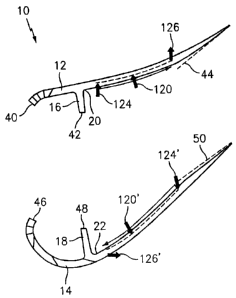
[0016] Referring now to the drawings, FIG. 1 illustrates an
airfoil portion 10 of a turbine engine component, such as a
high pressure turbine blade. The airfoil portion 10 has a
first half 12 and a second half 14. The airfoil halves 12 and
14 may have any desired shape and may include internal
structures, such as ribs 16 and 18. As will be discussed
hereinafter, the airfoil halves 12 and 14 are formed so that
respective internal wall surfaces 20 and 22 are exposed.
[0017] The airfoil halves 12 and 14 may be cast in any
suitable manner known in the art from any suitable material
known in the art. For example, the airfoil halves 12 and 14
may be formed from a nickel-based, cobalt-based, iron-based,
or titanium-based alloy material.
[0018] In a preferred embodiment of the present invention, the
airfoil halves 12 and 14 are formed using a casting unit 24
such as that shown in FIG. 2. The casting unit 24 is unique in
that it casts a structure 100, such as that shown in FIG. 5,
from which the turbine engine component can be formed. The
structure 100 may include a platform 102 having a leading edge
3
EH-11578(05-471)
CA 02558479 2006-08-25
104, a trailing edge 106, a first side edge 108, and a second
side edge 110. The structure 100 also may include the first
airfoil half 12 along the edge 108 and the second airfoil half
14 along the edge 110. The structure 100 may also have
features such as an attachment portion (not shown) formed on
an underside of the platform 102 and fillets 112 formed
between an exterior surface 114 or 116 of a respective one of
the airfoil halves 12 and 14 and a surface of the platform
102. One of the advantages to the structure 100 is that the
internal wall surfaces 20 and 22 are exposed prior to the
halves 12 and 14 of adjacent ones of the structures 100 being
joined together. Because the internal wall surfaces 20 and 22
are exposed, one or more cooling microcircuits can be easily
formed on the internal wall surfaces 20 and 22. The shape of
the microcircuits can be selected to optimize the cooling
needs of the airfoil portion 10 in its intended environment.
[0019] To form the structures 100, the casting unit 24 is
separable along the lines A - A and B - B which define the
split line 26 for the airfoil portion 10. The casting unit 24
is different from prior art casting units wherein the airfoil
portion was formed without any split lines. Instead, there was
a parting line in a center portion of the platform. Forming
the turbine component structures in this manner was
disadvantageous in that there were a plurality of leakage
paths between adjacent platform portions which required the
use of numerous seals. This disadvantage is overcome by the
casting unit 24 used to form the structures 100 because the
platform portions are now cast as a single unit eliminating
the need for seals as it is configured today along the
platform edges. In use, the casting units 24 may be filled
with a molten material in any suitable manner known in the
art. That is, create the mold with wax, shell the mold,
liquefy the wax, and pour the liquid metal in the pattern
(empty spaces) during casting.
4
EH-11578(05-471)
CA 02558479 2006-08-25
[0020] FIG. 3 illustrates one form of a split line 26 which
can be used in the casting units 24 in carrying out the
present invention to form the airfoil halves 12 and 14. FIG. 4
illustrates an alternative embodiment of a split line 26'
which can be used in the casting units 24 carrying out the
present invention to form the airfoil halves 12 and 14.
[0021] Referring to FIGS. 1 and 6, a first cooling
microcircuit 120 can be formed on the internal wall surface 20
using any suitable technique known in the art. For example,
the microcircuit 120 can be a cast structure if desired where
a number of elements 122, such as pedestal structures, which
define one or more passageways for a cooling fluid, as well as
an inlet 124 and an outlet 126 for the passageways, are cast.
Alternatively, the microcircuit 120 can be machined, using any
suitable technique known in the art, to form the elements 122
which define the passageways) for the cooling fluid and the
inlet 124 and the outlet 126 for the passageway(s). As noted
above, the exact configuration of the microcircuit 120 is a
function of the end use of the turbine engine component. FIGS.
7A and 7B illustrate exemplary cooling microcircuit
configurations which can be used in the present invention. An
advantage to forming the microcircuit 120 in this manner is
that it can be easily inspected prior to assembly of the
airfoil portion lo.
[0022] After or before, the microcircuit 120 has been
inspected, a cover plate 128 may be placed over it and joined
to one or more of the elements 122.
[0023] In a similar fashion, a second microcircuit 120' may be
formed on the internal wall surface 22 of the airfoil half 14.
As with the first microcircuit 120, the second microcircuit
120' may be formed using any suitable technique known in the
art and may have any number of cooling passageways. The
microcircuit 120' also has a plurality of elements 122'
defining one or more passageways for the cooling fluid, and an
EH-11578(05-471)
CA 02558479 2006-08-25
inlet 124' and an outlet 126' for the cooling fluid
passageway(s). After or before the microcircuit 120' has been
inspected, a cover plate 128' may be placed over the
microcircuit 120' and joined to the elements 122'.
[0024] The cover plates 128 and 128' may be joined to the
elements 122 and 122' of the respective microcircuits 120 and
120' using any suitable technique known in the art such as
brazing, diffusion bonding, and welding. It should be noted
that one advantage to this approach is that the cover plates
128 and 128' can easily be replaced if dirt plugging becomes a
problem in the field.
[0025] After the microcircuits 120 and 120' have been formed
and inspected and the cover plates 128 and 128' have been
installed, the structures 100 are ready to be installed in a
support structure (not shown) such as a disk. Adjacent ones of
the structures 100 form an airfoil portion 10 by placing the
airfoil half 12 in an abutting relationship with the second
airfoil half 14 wherein mating surfaces 40, 42, and 44 on the
airfoil half 12 contact or abut mating surfaces 46, 48, and 50
on the airfoil half 14. If desired, the airfoil halves 12 and
14 may be joined to each other using any suitable means known
in the art such as by mechanical devices, diffusion bonding,
transient liquid phase bonding, or solid state bonding.
[0026] As can be seen from the foregoing discussion, the
technology employed in the present invention provides a simple
means to implement microcircuit features in an airfoil design
without the complexity associated with double-wall cooling
designs. The present invention facilitates internal
inspection, resolves the plugging problems, and improves
performance by eliminating numerous leakage paths.
6