Note: Descriptions are shown in the official language in which they were submitted.
CA 02558750 2006-07-12
' ' FP060005US
Electrical Depilator
BACKGROUND OF THE INVENTION
Field of the Invention
The present invention relates to an electrical depilator, in particularly, to
an
electrical depilator which is easy in die sinking, convenient in assembling,
and of
low cost.
Description of the Related Art
There are various electrical depilators with different constructions in
conventional technology and there are a great many patents relating to
depilators.
Fig. 1 shows a type of depilator among conventional ones. The depilator
comprises
a main body 1', a motor 2', a reduction gear set 3', an arcuate shaft 4', a
set of
base pieces 5' and thin clipping pieces 6'. Each clipping piece 6' is fixed on
a
corresponding base piece 5', that is, the thin clipping piece 6' is supported
on and
driven by the base piece 5' to move correspondingly. The whole set of base
pieces
5' are coupled together by shifting yokes (not shown, or by bearing housings
or
shaft pins) so as to rotate synchronously. The whole set of base pieces 5' and
the
thin clipping pieces 6' are fitted over the arcuate shaft 4' which is
supported on a
shaft seat of the main body 1'. A first stage gear of the reduction gear set
3'
meshes with a driving wheel of the motor 2', and a last stage gear is fixed on
the
2s base piece 5' which is located at the endmost position.
When it is energized, the driving wheel of the motor 2' drives the whole set
of base pieces 5' and the thin clipping pieces 6' supported on the base pieces
5'
through the reduction gear set 3' to rotate around the arcuate shaft 4'.
Thereby, the
clipping pieces 6' on the gradually-narrowed side of the arcuate shaft 4' are
caused
3o to perform a clipping action by the way of being pressed by the base pieces
5', and
those on the gradually-widened side of the arcuate shaft 4' perform a
loosening
action. Thus, hairs are depilated rapidly on the gradually-narrowed side of
the
arcuate shaft 4' by the clipping pieces 6', while the depilated hairs are
thrown into
the hair-collecting box on the gradually-widened side of the arcuate shaft 4'.
35 Therefore, such depilator can depilate hairs rapidly.
CA 02558750 2006-07-12
' ~ FP060005US
However, it can be readily appreciated that the above-mentioned depilator
has the following disadvantages after a close study of its structure.
The depilator comprises a plurality of base pieces 5' performing pressure
transfer and motion functions and thin clipping pieces 6' supported by the
pieces 5'
s and performing a hair clipping function. In addition, the plurality of base
pieces 5'
and the clipping pieces 6' are arranged alternately in the following manner:
one
base piece 5'~ two thin clipping pieces 6' ~ one base piece 5'...and so on.
Thus,
there are too many members, which need die sinking not only for forming base
piece 5' but also for forming thin clipping pieces 6'. Therefore, it is
difficult in die
1o sinking. Furthermore, the cost of manufacture is high because the structure
of the
depilator is complicated and the thin clipping pieces 6' are generally made of
metals. Moreover, the assembling procedure is very troublesome because of the
alternate arrangement in the form of one base piece 5'~ two thin clipping
pieces 6'
-j one base piece 5'...and so on.
Is
Summary of Invention
In view of the above disadvantages in the conventional art, it is an object of
the present invention to provide an electrical depilator which is easy in die
sinking,
convenient in assembling, and of low cost.
2o In order to achieve one or more aspects of the above object, the present
invention provides the following technical schemes:
An electrical depilator, comprising substantially a main body, a motor, a
reduction gear set, an arcuate shaft and a set of single-pieces. The arcuate
shaft is
supported on a shaft seat of the main body. A first stage gear of the
reduction gear
25 set meshes with a driving wheel of the motor, and a last stage gear is
fixed on the
single-piece which is located at the endmost position. Each single-piece has a
clipping surface and a supporting portion. The whole set of single-pieces are
arranged with the clipping surfaces opposite to each other. A clipping gap is
formed
between the opposite surfaces of two single-pieces. The whole set of single-
pieces
3o are coupled together by fixing members to rotate synchronously. The whole
set of
single-pieces are fitted over the arcuate shaft all together.
The fixing members are shifting yokes which are formed on both sides of
each single-piece. One shifting yoke on a single-piece is inserted into and
locked
with another shifting yoke of an adjacent single-piece, thus the whole set of
35 single-pieces are coupled together and rotated synchronously.
2
CA 02558750 2006-07-12
FPO60005US
The fixing members are fork bodies which are provided with shaft holes at
centers thereof corresponding to the position of the arcuate shaft. Each
single-piece is provided at both sides with fork shaped slots. Both sides of
each
fork body are inserted into and locked with two fork shaped slots of two
adjacent
single-pieces, thus the whole set of single-pieces are coupled together and
rotated
synchronously.
A thin piece is fixed on each fork body. The thin pieces and the fork bodies,
together with the whole set of single-pieces, are fitted over the arcuate
shaft. The
thin piece is provided between two opposite clipping surfaces of two single-
pieces,
1o and two clipping gaps are formed between both sides of each thin piece and
clipping surfaces of two single-pieces, respectively.
The fixing members are bearing housings. The whole set of single-pieces
are coupled together by the bearing housings to be rotated synchronously.
The fixing members are shaft pins. The whole set of single-pieces are
coupled together by the shaft pins to be rotated synchronously.
With the above structure, when energized, the driving wheel of the motor
drives the whole set of singe-pieces through the reduction gear set to rotate
around
the arcuate shaft. Thereby, the single-pieces on the gradually-narrowed side
of the
arcuate shaft are caused to perform a clipping action, and those on the
2o gradually-widened side of the arcuate shaft perform a loosening action.
Thus, hairs
are depilated quickly on the gradually-narrowed side of the arcuate shaft
directly by
use of the clipping surfaces of the singe-pieces, so as to depilate hairs
quickly.
The electrical depilator according to the present invention has the following
advantages over the prior arts. The depilator only has a plurality of single-
pieces.
That is, the two types of pieces in the conventional art, i.e. the base pieces
performing pressure transfer and motion functions and the thin clipping pieces
supported by the pieces and performing a hair clipping function, are
simplified as
one type of single-pieces. As a result, the thin clipping pieces are
eliminated. Thus,
the number of members is reduced, which facilitates the die sinking because
only
3o the die for forming single-pieces is needed. In addition, the structure is
greatly
simplified and only the single-pieces are required to be assembled in
assembling.
Therefore, the assembling procedure is easy and the cost is reduced.
Brief Description of the Drawings
Fig. 1 is a schematic view showing the structure of a conventional electrical
3
CA 02558750 2006-07-12
' ' FPOGOOOSUS
depilator;
Fig. 2 is a view showing an appearance of the depilator according to one
embodiment of the present invention;
. Fig. 3 is a partial exploded perspective view of the depilator according to
one
s embodiment of the present invention;
Fig. 4 is a side view of a single-piece according to one embodiment of the
present invention;
Fig. 5 is a top view of a single-piece according to one embodiment of the
present invention;
to Fig. 6 is a bottom view of a single-piece according to one embodiment of
the
present invention;
Fig. 7 is a perspective view of a single-piece according to one embodiment
of the present invention;
Fig. 8 is another perspective view of a single-piece according to one
15 embodiment of the present invention;
Fig. 9 is a perspective view of the whole set of single-pieces assembled on
an arcuate shaft according to one embodiment of the present invention;
Fig. 10 is a view partially showing the parts in Fig. 3 being assembled;
Fig. 11 is a partially exploded perspective view according to another
2o embodiment of the present invention;
Fig. 12 is a perspective view of a single-piece according to another
embodiment of the present invention;
Fig. 13 is another perspective view of a single-piece according to another
embodiment of the present invention;
2s Fig. 14 is a perspective view of a fork body according to another
embodiment of the present invention;
Fig. 15 is a partially exploded perspective view according to yet another
embodiment of the present invention;
Fig. 16 is a perspective view showing the fork body and the thin piece being
3o assembled according to yet another embodiment of the present invention.
DETAILED DESCRIPTION OF THE PREFERRED EMBODIMENTS
Embodiments of the present invention will be described in detail with
reference to attached drawings.
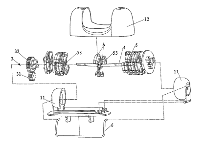
3s As shown in Fig. 2 in conjunction with Fig. 3, an electrical depilator
4
CA 02558750 2006-07-12
' ~ FP060005US
according to one preferred embodiment of the present invention comprises a
main
body 1, a motor (not shown), a reduction gear set 3, an arcuate shaft 4 and a
set of
single-pieces 5.
The arcuate shaft 4 is supported on a shaft seat 11 of the main body 1.
A first stage gear 31 of the reduction gear set 3 meshes with the driving
wheel (not shown) of the motor, and a last stage gear 32 is fixed on the
single-piece 5 which is located at the endmost position.
Each single-piece 5 has a clipping surface 51 and a supporting portion 52,as
shown in Figs. 4-8. The whole set of single-pieces 5 are arranged in such a
manner
io that the clipping surfaces 51 are opposite to each other. A clipping gap A
is formed
between the opposite surfaces 51 of two single-pieces 5, as shown in Figs. 2
and 3.
The whole set of single-pieces 5 are coupled together by fixing members so as
to
rotate synchronously. The fixing members can have a variety of specific
structures.
As shown in Figs. 4-8 of this embodiment, the fixing members are shifting
yokes 53
which are formed on both sides of each single-piece 5. One shifting yoke 53 on
each single-piece 5 is inserted into and locked with another shifting yoke 53
on the
adjacent single-piece 5, thus the whole set of single-pieces 5 are coupled
together
and rotated synchronously. In another embodiment, the fixing members can also
be
fork bodies 54 shown in Fig. 14 which have three fork feet 542 respectively
and are
2o provided with shaft holes 541 at centers thereof corresponding to the
inserting
position of the arcuate shaft 4. As shown in conjunction with Figs. 12 and 13,
each
single-piece 5 is provided at both sides thereof with fork shaped slots 501.
Both
sides of each fork body (that is, the three fork feet 542) are inserted into
and locked
with two fork shaped slots 501 of two adjacent single-pieces 5, thus the whole
set
of single-pieces 5 are coupled together and rotated synchronously. The fixing
members can also be bearing housings which are not shown in drawings, by which
the whole set of single-pieces 5 are coupled together and rotated
synchronously.
The fixing members can also be shaft pins which are not shown in drawings, by
which the whole set of single-pieces 5 are coupled together and rotated
3o synchronously. Referring to Figs 9 and 11, the whole set of single-pieces 5
are
fitted over the arcuate shaft 4 all together.
To facilitate the assembling of the single-pieces 5 in the set, in the
embodiment, firstly the whole set of single-pieces 5 are mounted on the shaft
seat
11 by the arcuate shaft 4 and are fixed by a spring 6. Then the arcuate shaft
4, the
3s reduction gear set 3 and the shaft seat 11 are covered by a shell 12, only
the whole
s
CA 02558750 2006-07-12
' ~ FP06000SUS
set of single-pieces 5 are exposed for depilating. Therefore, the depilator
has a
good appearance, as shown in Fig. 10.
With the above structure according to the present embodiment, when
energized, the driving wheel of the motor drives the whole set of singe-pieces
5
through the reduction gear set 3 to rotate around the arcuate shaft 4.
Thereby, the
singe-pieces 5 on the gradually-narrowed side of the arcuate shaft are caused
to
perform a clipping action, and those on the gradually-widened side of the
arcuate
shaft perform a loosening action. Thus, hairs are depilated on the
gradually-narrowed side of the arcuate shaft directly by use of the clipping
surfaces
of the singe-pieces 5 so as to depilate hairs quickly. Two types of pieces in
the
conventional art, i.e. the base pieces 5' and the thin clipping pieces 6', are
simplified as a type of single-pieces in the present invention, with the thin
clipping
pieces 6' being eliminated. Thus, the number of members is reduced, which
facilitates the die sinking because only the die for forming single-pieces 5
is needed.
1s In addition, the structure is greatly simplified and only the single-pieces
5 are
required to be assembled during the assembly process. Therefore, the assembly
is easy and the cost is reduced.
As shown in Figs. 15-16, a thin piece 55 is fixed on each fork body 54 shown
in Fig. 14 according to yet another embodiment of the present invention. The
thin
2o pieces 55 and the fork bodies 54, together with the whole set of single-
pieces 5,
are fitted over the arcuate shaft 4. The thin piece 55 is provided between two
opposite clipping surfaces 51 of two single-pieces 5, and two clipping gaps A
are
formed between both sides of each thin piece 55 and clipping surfaces 51 of
two
single-pieces 5, respectively. (That is, the gap A in Fig. 2 is divided into
two parts.)
25 Compared with the conventional art, two thin pieces are eliminated in this
embodiment. Therefore, it is easy in die sinking, convenient in assembling,
and of
low cost. In addition, compared with the above two embodiments, this
embodiment
has twice the gaps with further introducing only one thin-piece 55. Thus, it
has a
better performance of depilating.