Note: Descriptions are shown in the official language in which they were submitted.
CA 02559121 2006-09-08
DESCRIPTION
BULK 50LIDZFIED QUENCHED MATERIAL AND METHOD FOR PRODUCTNG
THE SAME
Technical Field
The present invention relates to a rapidly solidified
material. consolidated into a bulk form and a method for
producing the same, and more particularly, relates to a
giarit magnetostrictive alloy or a shape-memory alloy and a
method for producing the same, the alloy being a bulk
rapidly solidified material which is produced by a liquid
rapid solidification method and a spark plasma sintering
method and which is used as a material for sensor and
actuator elements.
F~ackground Art
By using a liquid rapid solidification method, various
amorphous, fine crystalline, and polycrystalline alloy-based
materials have been developed. Functional materials, such
as a shape-memory alloy, in the form of a thin belt, a thin
wire, and a powder can be formed by a liquid rapid
solidification method (Patent Documents 1 and 2).
As for an iro~i-based magnetic shape-memory alloy, one
(Furuya) of the inventors of the present invention found a
giant magnetostrictive effect by using a 7,iquid rapid
solidification method which is equivaJ.ent to the level of
- 1 -
CA 02559121 2006-09-08
Terfenol-D known as a giant magnetostrictive material. This
new magnetostrictive material is a practical polycrystalline
material having a particular crystal controled texture which
is fine and has strong directionality peculiax to a rapidly
solidified material, and a patent application relating to a
polycrystalline Fe-Pd-based and a Fe-Pt-based alloy was
filed (Patent Document 3). In addition, the inventors of
the present invention reported properties of a thin belt-
shaped sample of a Fe-l5at~ Ga alloy which was annealed for
a short period of time (1,173K for 0.5 hour) (Non-Patent
Document 3).
Furthermore, it was also found that when a NiCoGa, a
CoNiGa-based alloy (Patent Document 4) and a Fe-Ga-based
alloy (Patent Document 5) are processed at a certain rapid
cooling rate, a fine columnar crystal texture having
significantly Strong crystalline anisotropy can be formed,
and that the material thus Controlled also has ductility and
can induce a magnetostrictive phenomenon 6 to 10 times or
more that of a conventional randomly oriented crystalline
matexial.
It has been disclosed that in a rapidly solidified
shape-memory alloy, because of crystal miniaturization
having a nano- to a micron-size scale and columnar crystal
(anisotropy) formation peculiar to a rapidly solidified
material, a shape~memory alloy composition (such as a thin
CA 02559121 2006-09-08
wire (fiber) and a thin belt (ribbon) made of Ti5pNi5p~xCuX
(x=8 atomic percent)) can be produced which could not been
pXOduced by a conventional melting and rolling process, and
that functional performances such as ductility, strength,
and shape-memory effect can be improved (Non-Patent
Documents 1 and 2).
In research relating to enhancement of performance of a
Ti-Ni-based shape~rnemory alloy (Non-Patent Document 5), the
result has been reported by Kajiwara et al. which was
obtained when a Ti-rich Ti-Ni-based thin film
(TiSgNiqpCu6(atomic percent)) approximately iri an amorphous
state foamed by a sputtering deposition method is annealed
at a low temperature compared to that of a conventional case.
According to this technical paper, there have been
reported that non-equilibrium phases such as Ti~Ni and TiNi3
having a highly dense tetragonal structure with a bct (body
centered tetragonal) lattice are precipitated on the {100)
plane of a TiNiB2 mother phase and form two types of
distributions (arrangements) depending on a slight
difference in annealing temperature; a uniform distribution
is obtained when annealing is performed in the vicinity of
an amorphous crystallization temperature (Tc), and a texture
is formed on boundaries of nanocrystals when annealing is
performed at a temperature slightly below the Tc; and the
shape-memory performance is enhanced by the change in
- 3 -
CA 02559121 2006-09-08
precipitation mode.
Zn addition, there has been reported that also as for a
~i~rich Ti-Ni-Cu thin film, the shape-recovery performance
thereof is further enhanced when bct precipitates axe
produced by annealing, and hence attention has started to be
paid to development of a rapidly Solidified material in the
form of a thin belt or the like having a larger shape-
recovery performance.
However, an alloy having high performances as described
above has been realized primarily by a thin belt or a thin
wire having a thickness or a diametex of approximately 200
~m or less, and it has been difficult to obtain a material
having predetermined properties by a melt method,
Heretofore, as a method for producing a bulk crystalline
alloy in the form of a plate, a bar, or the like having a
thickness or a diameter in the order of millimeters or more,
besides a melt method, a powder metallurgical method has
been known. As one powder metallurgical method, a spark
plasma sintering method has been known (for example, see
Non-Patent Document 4 and Patent Document 6).
In the spark plasma sintering method, high energy
pulses can be Concentrated on positions at which
intergranular bonds are intended to be formed, and hence a
sintering process dynamically pxoeeeds. This is the feature
of the spark plasma sintering process and is significantly
- 4 -
CA 02559121 2006-09-08
different from a general quasi-static sintering method such
as hot pressing or resistance sintering. Sznce rapid
temperature zncrease only on grain surfaces can be performed
by self-heating, while the grain growth of a sintering raw
material is suppressed, a dense sintered body can be
obtained within a short period of time. In addition, Since
the texture inside the sintering raw matexial can be
prevented from being changed, a powdered material having an
amorphous structure or a nanocrystalline texture can be
formed into a bulk shape such as a plate or a bar while
maintaining its own structure or texture. By using this
electrical spark plasma sintering method, a Fe-Dy-Tb-based
or a rare earth element-transition metal-based giant
magnetostrictive material formed into a deSixed shape has
been developed (Patent Documents 7, 8, and 9).
Patent Document 1: Japanese Unexamined Patent Application
Publication No. 1-212728 (Japanese Patent No, 2589125)
Patent Document 2: Japanese Unexamined Patent Application
Publication No. 6-172886
Patent Document 3. Japanese Unexamined Patent Application
Publication No, 11-269611
Patent Document 4: Japanese Unexamined Patent Application
Publication No. 2003-96529
Patent Document 5: Japanese Unexamined Patent Application
Publication No. 2003-26550
- 5 -
CA 02559121 2006-09-08
Patent Docum2'nt 6: Japanese Unexamined Patent Application
Publication No. 6-341292 (Japanese Patent No. 2762225)
Patent Document 7: Japanese Unexamined Patent Application
Publication No. 5-105992
Patent Document 8: Japanese Unexamined Patent Application
Publication No. 11-189853
Patent Document 9: Japanese Unexamined Pat2rit Application
Publication loo. 2001-358377
Non-Patent Document 1: authored by Yasubumi Furuya, Chihiro
Saito, and Teiko Okazaki, J. Japan Inst. Metals, vol. 66, pp.
901 to 904, (2002).
Non-Patent Document 2: authored by Yamahira, Shinya, Tamoto,
Aiba, Kise, and Furuya, J. Japan Inst. Metals, vol. 66, No.
9, pp. 909 to 912, (2002).
Non-Patent Document 3: authored by C. 5aito, Y. Furuya, T,
Okazaki, T. Watariabe, T. Matsuzaki, and M. Wuttig, Mater.
Trans., JIM, vol, 45, pp. 193 to 198, Feb, (2004).
Non-Patent Document 4: authored by M. Omori, Mater. Sci. Eng.
A, vol. 287, pp. 183 to 188, Aug. (2000).
Non-Patent Document 5: authored by K, Yamazaki, S. Kajiwara,
T. Kxkuchi, Kogawa arid 5. Miyazaki, Proc. ICOMAT-2002, Jun.
235-249, (2002) .
Disclosure of Invention
Problems to be Solved by the Invention
A rapidly solidified material produced by a liquid
- 6 -
CA 02559121 2006-09-08
rapid solidification method has superior performance;
howevez, because of restrictions by the rapid cooling
process, the material thus obtained has a very small
thickness or diameter such as a plate material having a
thickness of approximately not more than 100 ELm or a wire
material having a diameter of approximately not more than
100 um. In addition, the maximum length of the rapidly
solidified material thus produced is approximately 2 m, and
a material having a considerably large length is difficult
to be produced. When the materials described above are used,
an actuating force thereof as an actuator element is small,
and the application of the materials is limited only to
micromachines and small sensor devices. In addition, since
superior properties because of a non~equilibrium phase and a
fine crystalline texture peculiar to a rapidly solidified
material disappear when it is annealed for a long period of
time, the improvement in alloy properties by annealing is
limited,
Heretofore, as for an iron-based Fe-Ga magnetostrictive
alloy, development by a single crystal method was performed
only in USA (by the Office of Naval Research, ONR), and a
magnetostriction of 300 ppm was reported. However, the
singly crystal method must be carried out under very severe
operation conditions, and in addition, single crystal
actuator and sensor materials are disadvantageously very
CA 02559121 2006-09-08
expensive.
In addition, a Ti-Ni alloy has been well known as a
temperature-sensitive shape-memory alloy and has been widely
spread in industrial applications. Furthermore, it has been
confirmed that when copper is added as a third element,
hysteresis of the 'transformation point can be decreased.
However, in a Ti-Ni alloy containing 8 atomic percent or
more of copper, by a conventional processing method in which
hot and cold rolling and drawing are repeatedly performed
after melting, embrittlement occurs during material
processing steps due to grain boundary segregation of Cu,
and hence it is difficult to obtain thin wire and thin belt
materials. As a result, the materials mentioned above
become very expensive, and although the value-adding
function thereof has been well known, the industrialization
has been difficult as of today.
Accordingly, as a material used for actuator and sensor
elements incorporated in mechanical and electronic
components and in intelligent material systems and
structures (aircrafts, automobiles, constructive structures,
sonar devices, electric devices) of industrial application
fields, development of bulk materials and that of production
methods thereof have been desired, the bulk materials having
workability to be formed into a complicated shape and having
a large mass so as to obtain a large recovery force.
CA 02559121 2006-09-08
An object of the present invention is to produce a bulk
material suitably used as a material for actuator and sensor
elements from a Fe-G~a-based magnetostrictive alloy and/or a
Ti-Ni-based shape-memory alloy taking advantage of crystal
miniaturization and anisotropy as well as reduction in
precipitates (equilibrium phase in state diagram) and non-
equilibrium phases peculiar to liquid rapidly solidified
materials, and to obtain performance enhancement by a
production method superior to the melt method in teams of
cost.
The present invention provides a bulk alloy having a
mass to a certain extent while superior properties of a
liquid rapidly solidified material are maintained.
According to the present invention, a bulk alloy is formed
by stacking slices in a die, which are formed from a rapidly
solidified material having a particular rapidly solidified
texture of a F'e-Ga magnetostrictive alloy or a Ti-Ni-based
shape-memory alloy and superior properties based on the
above texture, or filling a powder or chops of the rapidly
solidified material in the die, followed by performing a
spark plasma sintering method, so as to generate bonds
between the slices, grains ox the powder, or the chops at a
krigh density. In addition, according to the present
invention, the bulk alloy thus sintered is further annealed,
so that the properties thereof are improved.
- g _
CA 02559121 2006-09-08
That is, the present invention is as follows:
(7.) a rapidly solidified material consolidated into a bulk
foam for actuators and sensors, comprising a Fe-Ga
magnetostrictive alloy which is obtained from slices, a
powder or chops of a Fe-Ga alloy rapidly solidified material
by spark plasma sintering, the Fe-Ga alloy rapidJ.y
solidified material having a high temperature-side
disordered bcc structure and a fine columnar texture by a
liquid xapid solidification method, being in a disordered to
ordered transition composition range, and containing I5 to
23 atomic percent of Ga with respect to polycrystalline Fey
(2) the rapidly solidified material consolidated into a bulk
form for actuators and sensors, according to the above (1),
wherein (001) crystal7.ine anisotropy of a xapidly solidified
thin belt o~ the Fe-Ga alloy is maintained;
(3) the rapidly solidified material consolidated into a bulk
form for actuators and sensors, according to the above (1),
wherein a magnetostriction of 7.70 to 230 ppm is obtained at
room temperature by annealing following the sintering;
(4) the rapidly solidified material consolidated into a bulk
form for actuators and sensors, according to the above (1),
wherein a magnetostriotion of 250 to 260 ppm is obtained at
room temperature by annealing in a magnetic field following
the sintering.
(5) a rapidly solidified material consolidated into a bulk
- 10 -
CA 02559121 2006-09-08
form for actuators and sensors, comprising a TiNiCu shape-
memory alloy which is obtained from slices, a powder or
chops of a TiNiCu shape-memory alloy rapidly solidified
material by spark plasma sintering, the TiNiCu shape-memory
alloy rapidly solidified material being composed of dri
amorphous to nanocrystalline texture or an amorphous and
nanocrystalline mixed texture by a liquid rapid
solidification method;
(6) the rapidly solidified material consolidated into a bulk
form for actuators and sensors, according to the above (5),
wherein the TiNiCu shape-memory alloy is Ti50+xNi40Cu10-x
(where x is in the range of 0 to 4 on an atomic percent
basis);
(~) a method for producing the rapidly solidified material
consolidated into a bulk form ~or actuators and sensors
according to one o~ the above (1) to (4), comprising the
steps of: forming a rapidly solidified material by a liquid
rapid solidification method from a Fe-Ga alloy having a high
temperature~side disordered bcc structure and a fine
columnar texture, being in a disordered to an ordered
transition composition range, and containing 15 to 23 atomic
percent of Ga with respect to polycrystalline Fe; forming
slices, a powder, or chops from the alloy as a raw material;
and performing spark plasma sintering of the raw material at
an application pressure of 50 MPa or more and at a sintezing
- 11 -
CA 02559121 2006-09-08
temperature of 873Ii or more under conditions iri which the
pressure and the temperature are controlled so that the
texture of the rapidly solidified material is not lost;
(8) a method for producing the rapidly solidified material
consolidated into a bulk form for actuators and sensors
according to the above (5) or (6), comprising the steps of:
forming a TiNiCu shape-memory alloy rapidly solidified
material which is composed of an amorphous to a
nanocrystallirie texture or an amorphous and nanocrystallirie
mixed texture by a liquid rapid solidification method;
forming slices, a powder, or chops from the alloy as a raw
material; and performing spark plasma sintering of the raw
material at a temperature less than a recrystallization
temperature of a TiNiCu shape~znemory alloy;
(9) the method for producing a rapidly solidified material
consolidated into a bulk form for actuators and sensors,
according to the above (8), wherein the TiNiCu shape-memory
alloy rapidly solidified material is wet-pulveXiaed by
rotary ball milJ.ing into slices, a powder, oz chops;
(10) the method for producing a xapidly solidified material
consolidated into a bulk form for actuators and sensors,
according to the above (9), wherein the wet-pulverizing is
performed using an alcohol;
(11) the method for producing a rapidly solidified material
consolidated into a bulk form for actuators and sensors,
- 12 -
CA 02559121 2006-09-08
according to one of the above (7) to (10), wherein annealing
is performed after the sintering; and
(12) the method for producing a rapidly solidified matexial
consolidated into a bulk form for actuators and sensors,
acCOrding to the above (11), wherein the cr;~sta1 orientation
of alloy properties is enhanced by annealing in a magnetic
field after the sintering, and the magnetic moment (magnetic
domain structure) d~.rectly relating to the magnetostriction
is controlled.
Advantages
The new bulk rapidly solidified Fe-Ga magn2tostrictive
alloy according to the present invention Can obtain
approximately 80~ of rnagnetostri.ction of a single
crystalline magr~etostrictive alloy, is significantly
inexpensive (approximately one twentieth) as compared to the
conventional rare earth-based Tefenol-D, and also has
superior workab~.~.ity (ductility) and high rigidity.
Accordingly, a rising strain energy density at an initial
magnetization stage can be increased. In addition, the bulk
Ti-Ni-based shape-memory alloy cari be formed into a large
bulk material having improved performances as compared to
that of an arc melted and processed material used as a
qtarting material, such as a narrow transformation point
width and a high mechanical strength (hardness) 1.4 times or
more than that of the arc melted and processed material, In
- 13 -
CA 02559121 2006-09-08
addition, acCOrding to the method of the pxesent invention,
rapidly solidified materials can be formed into a bulk shape
by a mass production process.
Best Mode for Carrying Out the Invention
fig. 1 shows steps of a method for producing a rap~.dly
solidified material consolidated into a bulk form according
to the pxesent invention. A material for sensor arid
actuator elements is first formed by a liquid rapid
solidi~ication method. An ingot as a raw material is formed
into a thin belt (r~.bbon) by a high-frequency induction
melting-liquid rapid solidification method (twin roll or
single roll quenching method). Alternatively, a thin wire
(fiber) is formed by plasma arc melting-melt extraction
rapid solidification method (conical-roll front-end spinning
method). Accordingly, a rapidly solidified material having
a fine columnar crystal texture, large crystalline
anisotropy, and non-equilibrium phase and the like can be
obtained.
A liquid rapid solidification method is frequently used
as a method for producing an amorphous aJ.loy and is also
effectively used when a material having poor workability,
such as a Fe-Ga magnetostrictive alloy or a Ti-Ni-based
shape-rnem~ry alloy, is formed into a sheet having a
thickness of 20 to 30 Eun. In a liquid rapidly solidified
alloy, because of crystal miniaturization having a nano- to
- 14 -
CA 02559121 2006-09-08
micron-size scale and columnar crystal (anisotropy)
formation, functional performances such as durability,
ductility, magnetostrictive effect, and shape-memory effect
can be improved.
Next, when the shape of a rapidly solidified material
is a slice having a length of approximately 20 to SO mm and
a thickness of 20 to 30 urn, a perform is formed by stacking
the slices in a die without pulverization and then can be
sintered. When the shape of a rapidly solidified material
is a long and thin belt, the material is cut to have a site
approximately equivalent to that of the above slice to form
a sintering raw material.
When a rapidly solidified material in the form of a
thin belt or a thin wire i,s pulverized into a powder, wet
pulverization is performed using rotary ball milling, that
is, pulverization is performed while thin belts or thin
wires are immersed in alcohol such a5 ethanol, so that a
powder or chops are obtained. For the pulverization, a
method using a planetary ball milling machine is pzeferable.
This is a method in which a powder can be obtained within a
short period of time by using centrifugal forces of balls
and mechanical energy with a wall of a container.
A Fe-Ga magnetostrictive ally or a Ti-Ni base shape-
memory alloy having a high hardness is difficult to be
pulverized, and in particular, since a Ti-Ni base alloy is
- 15 -
CA 02559121 2006-09-08
very hard, a considerable amount of energy is required for
pulverization. Even when pulverization is performed, heat
is generated thereby so as to enable an active Ti to cause
reaction with surrounding impurities, moisture, and an
oxidz2ing atmosphere, and as a result, the composition
having shape-memory properties is changed, However, the
inventors of the present invention found that when a wet
pulverizing method using a high purity alcohol is employed,
the change in atmosphere and the increase in heat can be
suppressed, and hence the change in composition can also be
suppressed.
Next, the powder or chops obtained by pulverization is
filled in a die to form a preform. The sintering raw
material laminated and placed in the die or that is filled
therein is processed by spark plasma sintering. As shown in
Fig. 2, the spark plasma sznrering is performed by filling a
sintering raw material 1 in a cemented carbide alloy die 2,
and applying a pressure by pushing an upper punch 3 and a
lower punch 9 therein. After those are fixed on a sintering
stage (not shownj in a chamber 5, and the inside of the
chamber 5 is evacuated by a vacuum pump 6, the sintering raw
material 1 is sandwiched by an uppex punch electrode 7 and a
lower punch electrode 8, and pulse electricity is applied
from a power source 9 while a pressure is being applied to
the sintering raw material. A sintering temperature is
16 -
CA 02559121 2006-09-08
controlled by a controller 11 while the temperature of the
die 2 is being monitored by a thermocouple 10.
When pulse electricity is applied, a high speed
diffusion effect is generated by high speed movement of ions
caused by the electric field. By applying the voltage and
the current repEatedly by this ON-OFF operation, since
discharge points and Joule heat generation points (local
high temperature-generation points) are moved in the
sintex~.ng raw material and entirely distributed therein, the
phenomenon and the effect obtained in the ON-state are
uniformly repeated in the sintering raw material, and as a
result, efficient sintering is performed in a solid phase
with a small power consumption.
The case in which a Fe-Ga magnetostrictive alloy is
produced by the above method will be described in more
detail. In Fig. 3, as for a Fe-Ga alloy, the difference is
shown between a thin belt material and a metal texture, the
thin belt material being composed of a representative
metastable phase (no precipitativri phase) formed by a rapid
solidification method, and the metal texture (Fe-Ga3, LZ2,
D03 ordered phase precipitation) being in accordance with a
phase equilibrium diagram, which is obtained by performing
general melting and processing, followed by annealing. The
liquid rapa.dly solidified thin belt material is obtained as
shown in Fig. 3 such that a molten metal 14 formed by
- 17 -
CA 02559121 2006-09-08
heating and melting a zaw material in a quartz crucible 12
by a high-frequency induction coil I3 is ejected by an Ar
gas onto a high speed rotation surface of a rotary roll 15
to form a ribbon 6.
By the liquid rapid solidification method, a phase
which generally appears only at a high temperature is first
allowed to appear at room temperature by rapid
solidification performed from a liquid phase. Second, at an
intermediate cooling rate, a fine columnax crystal texture
is formed. Since this texture is finer than a conventional
polycrystalline material, it has a high strength, and since
the thermal ,flow direction in solidification is along one
axis, an anisotropic texture having strong orientation in
that direction can be obtained. In a Fe-Ga alloy, when the
magnetic anisotropy is controlled, a functional material
having superior energy efficiency can be obtained.
In a Fe-Ga alloy, a Fe100-xGax single crystal obtained
by a general melting and processing method has a disordered
bcc structure when x is 19 atomic percent or less, and the
magnetostrictive constant is increased to 20 times that of
Fe. Furthermore, when those single crystals are rapidly
solidified from a high temperature, the magnetostrictive
constant is further increased. However, it was reported
that in an alloy in which x is 20 atomic percent or more,
the magnetostrictive constant (saturated magnetostriction)
- 18 -
CA 02559121 2006-09-08
is decreased (authored by T. A. Lograsso, A. R. Ross, D. L.
Shlagel, A, E. Clark, and M. Wun-Fogel, "J, Alloys and
Compounds" 35095-101 (2003)).
The change in the saturated magnetostriction of a Fe-Ga
alloy with the change in composition will be described.
According to the Ga concentration dependence of the magnetic
moment per atom of a bcC Fe-Ga alloy (authored by N.
Kawamiya, K. A. Adachi, and Y. Nakamura "J. Physics Soc.
Japan. 33, 1218-1327, 1972), up to approximately 15 atomic
percent of Ga, the Change is as if Fe is Simply diluted with
Ga, At the Ga concentration more than the above, the change
becomes different from the simple dilution behavior, and at
a Ga concentration of 20 atomic percent or more, as the
ordering proceeds, the magnetic moment is zapidly decreased.
The reason for this is believed that when Fe is being
surrounded by Ga, the magnetic moment of Fe itself is
decreased. In addition, the ordered structure formation
also begins to relate to the change in spontaneous
magnetization.
Furthermore, according to the phase equilibrium diagram
(not shown), the crystal structure is changed from a
disordered bcc phase to ordered phases (D03, L12) at
appzoximately 700°C in a region at a Ga concentration of 20
atomic percent or more, and hence it is believed that this
structural change relates to the magnetostrictive value.
- 19 -
CA 02559121 2006-09-08
Accordingly, when a high-temperature disordered bac phase is
frozen Lo room temperature by a liquid rapid solidification
method without precipitating ordered phases of a Fe-Ga alloy,
a larger magnetostriction can be expected.
Accordingly, it is important that alloy thin belts be
formed by rapid solidification method and laminated to each
other without performing any modification, followed by Spark
plasma sintering, the alloy thin belts having a high
temperature-side disordered bcC structure and a f~.ne
columnar texture, those are not formed by a general melting
and processing method, being in a disordered to ordered
transition composition range, and containing 15 to 23 atomic
percent of Ga with respect to polycrystalline Fe.
When the application forces by the upper and lower
punches and the sintering temperature in spark plasma
sintering are changed, the magnetic and magnetostrictive
properties of a sintered material are changed. In order to
complete the sintering while maintaining a fine crystal
texture formed by the liquid rapid solidification method, it
is preferable that in the spaxk plasma sintering, the
pressure be increased as high as possible and that the
sintering be performed at a low temperature. A Fe-l7at~ Ga
alloy thin belt can be sintered at an application pressure
of 50 MPa or more and a sintering temperature of 873K or
more during spark plasma sintering. The ratio of the
- 20
CA 02559121 2006-09-08
dErlsity of a sample sintered under 100 MPa at 973K is
approximately 100'x.
When the material sintered under 100 MPa at 973K was
annealed for a short period of time, a magnetostriction of
170 to 230 ppm was obtained at room temperature. When
annealing in a magnetic field is performed after sintering,
the crystal orientation of the alloy properties can be
enhanced, and in addition, the magnetic moment (magnetic
domain structure) d~.rectly relating to the magnetostriotion
can be controlJ.ed. When the above sample was processed by
annealing in a magnetic field after the sintering, the
magnetostriction was increased to 250 to 260 ppm, The
reason for this is believed that the magnetic (domains)
structures which move and rotate and which are responsible
for the magnetostriction generation mechanism are aligned in
a magnetic field processing direction at a nano to a meso
level, and as a result, the magnetic rotation is promoted at
a micron level with respect to external magnetic field
application, so that the magnetostriction is promoted.
From the results described above, it is preferable that
in order to obtain a large magrietostriction, the texture
peculiar to a liquid rapidly solidified thin belt be not
changed, and in addition, in order to sufficiently bonds
thin belts to each other, the application pressure and the
sintering temperature be Set to 50 MPa or more and B73K or
- 21 -
CA 02559121 2006-09-08
more, respectively. The upper limit of the application
pressure and that of the sintering temperature must be
determined so as not to lose the texture of the rapidly
solidified material.
Besides the properties of the liquid rapidly Solidified
material before spark plasma sintering, pulverization
conditions of the material also has influence on the
properties of a bulk alloy. Alcohol-wet milling is
effective to maintain the properties of a rapidly solidified
material. In particular, since titanium is a very active
element, it is preferable that titanium be prevented from
reacting with oxygen in an atmosphere and/or carbon from a
die during milling and discharge plasma sintering. When the
reaction once occurs, the content of titanium in a Ti-Ni-
based shape-memory alloy is decreased, and as a result, the
transformation point tends to decrease lower than that of
the original material.
In a spark plasma sintered bulk material formed fxom a
pulveri2ed material (powder, chops) in which the functional
properties of a Ti-Ni rapidly solidified material were
allowed to remain as much as possible, a thermoelastic phase
transformation phenomenon could also be confirmed by DSc.
In a Ti-rich TiNiCu base maternal, it was confirmed that a
large bulk material having improved performances as compared
to an arc melted and processed material used as a starting
- 22 -
CA 02559121 2006-09-08
material, such as a narrow temperature transformation width
and a high mechanical strength (hardness) approximately 1.5
times as large as that of the arc melted and processed
material, can be obtained by spark plasma sintering
(sintering conditions: Sintering temperature of 873K, and a
pressure of 300 MPa) for bonding of thin belts which are
placed in a ultra-rapidly rapidly solidified amorphous to
nanocrystalline state.
A bulk material of Ti5pNi4pCulp having a 90~ density can
be obtained under spark plasma sintering conditions in which
the pressure is set to a die limit pressure of 300 MPa, and
in addition, under a temperatu7re condit~.on of 400°C ox more.
This temperature condition is lower than a recrystallization
temperature of the TiNiCu alloy of 600°C, and hence the
rapidly solidified material is not recrystallized and
maintains its fine crystal texturE.
EXAMPLE 1
A Fe~l7at$ Ga alloy ingot was ~ormed by melting
electrolytic iron and Ga by a plasma arC melting method.
This ingot was melt and was formed into a thin belt 2 m long,
mm wide, and 80 fun 'thick in an argon atmosphere by a
liquid rapid solidx~ication (single roll) method. This thin
beJ.t was cut into slices 40 mm long to be used for a
discharge plasma sintering sample,
After 300 slices were stacked together in a cemented
- 23 -
CA 02559121 2006-09-08
carbide alloy die, sintering was performed for Sample (a)
under 50 MPa at 973K, Sample (b) under 100 MPa at 973K, and
Sample (c) under 300 MPa at 873K, and the sintering time was
set to 5 minutes. As a spark plasma sintering apparatus,
SPS 1050 manufactured by Sumitomo Coal Mining Co., Ltd. was
used. The spark plasma sintering was performed at a vacuum
degree of 2 Pa, a current of 3,000 A, and a voltage of 200 V.
The temperature rising conditions were different depending
on the temperature; however, it was approximately 30 minutes,
The size of the sample after the sintering was 40 mm long, 5
mm wide, and 9 mm thick (in the direction perpendicular to
the surface of the thin belt), For comparison purposes, a
sample (equivalent to that described in Non-Patent Document
2) was prepared which was obta~.ned by annealing an as-
rapidly-solidified Fe-l5at~ Ga alloy thin belt at 1,173K for
0.5 hours,
<X-ray structure analysis>
The analysis of the crystal structure of each sintered
sample was performed by analyzing the peak o~ the CuKal line
using an X-ray diffraction method. Fig. 4 shows X-ray
diffraction patterns of Samples (a), (b) and (c), which were
the sintered samples of the Fe-l7at~Ga alloy, and Sample (d)
of a comparative example. The three types of sintered
samples are formed of a body-centered cubic structure having
a lattice constant of 0.2904 nm. The intensity of the (200)
- 2A -
CA 02559121 2006-09-08
peak of Sample (b), the sample sintered under 100 MPa at
973K, is strong as compared to that of the other sintered
samples and is Similar to the diffraction pattern of Sample
(d1 of the comparative example having a strong j100]
orientation. 'this result indicates that in Sample (b), the
[100] texture of the thin belt is maintained.
Since Sample (a), the sample sintered under 50 MPa at
973K, has the (200) peak although it is weaker than that of
Sample (b), the sample sintered under 100 MPa at 973K, the
texture is maintained. On the other hand, the (200) peak of
Sample (c), the sample sintered under 300 MPa at 873K, is
small and spread, and hence the texture of the thin belt is
lost. The reason for this is believed that an application
pxessure of 300 MPa causes plastic deformation and internal
damage.
<Magnetization and magrietostriction measurement>
For the magnetization measurement, by using a vibrating
sample magnetometer (VSM), a magnetization-magnet~.c field
hysteresis Gurve (M-H loop) was measured at a maximum
magnetic field of 10 kOe. Furthermore, as shown in Fig. 5,
by using a measurement device formed of 2 brass plates 18,
brass screws 19, and an acrylic resin 20, strain gauges 17
were adhered to a sample 21, and the magnetostri.ction
parallel to the thickness direction was measured.
A Compressive stress of 20 MPa, 60 MPa, or 100 MPa was
- 25 -
CA 02559121 2006-09-08
applied to the sample as a pre-stress, and the
magnetostricti~re value was determined by the average of the
~ralues obtained by the strain gauges 17 provided on the
front and the rear surface of the sample. For the
magnetization and the magnetostri.Ction measu~'ement, a Fe-
l7at~ Ga alloy sintered sample was Cut to have a length of
2.7 mm, a width of 5 mm, and a thickness (in the direction
perpendicular to the surface of the thin belt) of 9 mm.
Since it has been reported (Non-Patent Document 2) that when
a magnetic filed is applied perpendicularly to the surface
of a thin belt, 3 large magnetostriction is obtained, a
magnetic field H was applied in the direction as described
above also in this example. The saturated magnetization was
1.68 Tesla and was haxdly changed even when the pre-stress
was changed.
Fig. 6 shows the magnetostriction of Sample (b), which
is the sample sintered under 100 MPa at 973K. The
magnetostriction considerably depends on a pre-stress s, is
saturated at a low magnetic field o~ 2 kOe, and is then
slightly decreased to the original value as H is increased.
A maximum magnetostriction of 100 ppm was obtained when a
pre-stress s ox 100 MPa was applied. The maximum
magnetostriction of Sample (a), the sample sintered under SO
MPa at 973K, was 70 ppm and was smaller than that of Sample
(b), which is the sample sintered under 100 MPa at 9'73K.
- 26 -
CA 02559121 2006-09-08
The reason for this is believed that since the stress in
sintez~ing was excessively small, bonds between the thin
belts were not sufficiently formed. Furthermore, since
Sample (c), the sample sintered under 300 MPa at 873K, had a
random texture, the magnetostriction thereof was smallest.
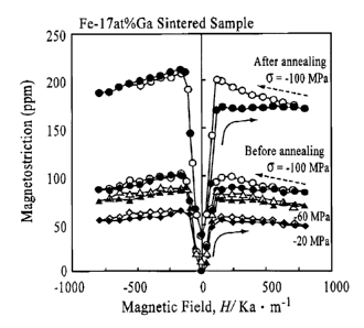
EXAMPLE Z
Sample (b), the sample sintered under 100 MPa at 973K,
produced by the method described in Example 1 was annealed
at 1,173K for 1 Your in a vacuum atmosphere. After the
annealing, the magrsetostriction was measured. Fig. 7 is a
graph showing the magnetostrictions o~ the sintered sample
before and after the annealing. The magnetostrictions
before and after the annealing at H of 2 k0e were 100 ppm
and x.70 to 230 ppm, respectively, and it was found that the
magnetoStriction was increased by the annealing.
Furthermore, when annealing in a magnetic field was
performed after the sintering, the magnetostriction was
increased to 250 to 260 ppm. The reason the
magnetostriction is increased when the thin belt sample is
annealed for a short period of time as believed that the
[100] orientation is enhanced so that the magnetostxiction
is increased [see Non-Patent Document 2], and in addition,
it is also believed that the magnetic moments (magnetic
domain structures) directly relating to the magnetostriction
which are aligned in a specific direction by application of
_ 27
CA 02559121 2006-09-08
an external magnetic field also relate to this increase in
magnetostriction.
EXAMPLE 3
[Example of TiNiCu shape-memory alloy]
Materials were weighed so as to have a composition of
Ti5pNi4pCulp (atomio percent) and were then formed into alloy
ingots as a raw material by a plasma arc melting method in
an argon atmosphere. Subsequently, from the ingots thus
formed, a thin belt (ribbon) was formed by a high frequency
induction melting-liquid rapid solidification method (twin
roll quenching method), and a thin wire (fiber) was formed
by plasma arc melting-mElt extraction rapid solidification
method (conical-roll Front-end spinning method), so that
rapidly solidified materials were obtained. The rapidly
solidified materials were wet-pulverized (in ethanol having
a purity of 99.995) by ball milling, so that Example A
(ribbon) and Example B (fiber) were obtained. In addition,
pulveriaati.on was performed in a dry atmosphere (in the air),
so that Comparative example A (ribbon) az~d Comparative
exampJ.e B (fiber) were obtained.
<Alloy properties of material after pulverization>
The DSC change with the milling time of the material
was investigated. In addition, the milled states and
crystal boundaries were observed by a scanning laser
microscope. When the transformation points of the rapidly
- 2B -
CA 02559121 2006-09-08
solidified thzn wire and thin belt, which were milled to a
powdered state (Comparative example A) in the air, were
measured with time, it was found that when the thin belt was
milled only for 5 minutes, the shape-memory effect was
substantially lost. Furthermore, when the milling was
performed for 55 minutes, the transformation point could not
be observed at all. The reason for this is construed as
follows. Since a Ti-Ni base alloy has poor workability,
when tk~e number of rotations is increased to form a powder,
heat is generated by bombardment during milling, and as a
result, the crystal Structure and/or the composition ratio
of the material is degraded.
The transformation point of the material which was
milled in liquid ethanol (examples) not in the air was
measured with time. The results a.re shown in Table 1.
Although the decrease in shape-memory properties is observed
to a certain extent thereby, when alloy properties after
consolidating into a bulk form using powdered materials
obtained by wet milling are compared, the decrease in shape-
memory properties is not so much observed,
Fig. 8 is the DSC measurement performed with the wet
milling time. From this figure, although the peak is
decreased as compared to the original material, the
transformation point tends to remain. The reason for this
is believed that the increase in temperature in the mill is
- 29 --
CA 02559121 2006-09-08
suppressed by the presence of ethanol.
<Alloy properties of spark plasma sintered bulk material>
The powders obtained by the above methods were
processed by bulk solidification using a spark plasma
sintering method in a manzter equivalent to that in Example 1
while low temperature-side short-time sintering conditions
were changed. The spark plasma sintering bulk formation
conditions are shown in Table 1. Furthermore, the obtained
samples were annealed at 673K for 30 minutes ~n a vacuum
atmosphere.
[Table 1]
ComparativeComparative ExampIeA Example
Exam le Exam le B a
A
Material sha Ribbon Fiber Ribbon Fiber
a
Quenched materialTwin roll Melt extractionTwin roll Melt extraction
formation method
Millin method in Air in Air in Ethanol in Ethanol
Milting (Time)Total 55 Total 80 min.Total BO Total 87
min. min. min.
(Number of 230 rpm 120 - 150 250 rpm 160 - 220
Rotations rpm rpm
SP5 pressure 0.72 ton 10 ton 10.04 ton 1.44 ton
condition
SPS temperature1,000C 600C 600C 1,000C
condition
Holdin time 10 min. 10 min. 5 min. 10 min.
Bulk formationYes Yes Yes Yes
Die material C die ovalWC+Co die WC+Co die C die oval
TransformationNo Present Present Present
oint
Ms - Mf No <68.1 > - <-16.5> - <34.3> -
tem erature ~75.6> <50.3> <56.6>
C
As - Af temperatureNo <54_ 1 > - <36.7> - <41.5> -
C <g2,g> <-27.9> <7.4>
- 30 -
CA 02559121 2006-09-08
whether the formed bulk shape-memory alloy samples
showed a shape-memory effect was confirmed by differential
thermal decomposition (DSC), and as for the sample which
showed a shape-meztiory effect, the trariSformation point
thereof was measuxed. The fiber had a Sharp and narrow peak
of the D5C curve showing the transformation point as
compared to that of the ribbon, and this indicates that the
fiber has superior response properties. The reason for this
is believed that sincE the fiber has superior pulverization
properties, even when the number of rotation is decreased, a
powdered material can be obtained which maintail~s alloy
properties of the rapidly solidified material. As for this
spark plasma sintered bulk TiNiCu sample havirig Clear phase
transformation observed by DSC, the shape-recovery
phenomenon was confirmed concomitant with the increase in
temperature.
Example 4
Materials were weighed so as to obtain a composition of
Ti5qNiqpCu6 (atomic percent) and were then formed into a
plasma arc melted alloy in an argon atmosphere. This alloy
was placed in a quartz tube and was melted by induction
heating, followed by formation of a ribbon-shaped sample by
using a liquid rapid solidification apparatus in an argon
atmosphere. The surface velocity of a rotary roll was
31 -
CA 02559121 2006-09-08
increased to the maximum (~ 5,430 rpm, a surface velocity Vr
of 45 m/s or more).
Th.e crystal structure of the sample thus formed was
measured by X-ray diffraction, Tc and the transformation
point were measured by a differential scanning calorimeter
(DSC), and propErties evaluation such as a tensile test and
the like was performed. In addition, the ribbon used for
the transformation point rneasuremerit was a ribbon which was
quenched at Tc for 1 hour, It. was confirmed that the ribbon
was changed so as to have an amorphous structure.
Subsequently, about 50 thin ribbons which were
approximately in an amorphous state were stacked together
in a die (having a length of 40 mm and a width of 3 mm) and
were processed by bulk solidification iri accordance with a
spark plasma sintering method in an argon atmosphere, As
the sintering conditions, the sintering temperature, the
pressure inside the chamber, and the holding time were 873K,
300 MPa, and 5 minutes, respectively. In order to
prefezentially obtain the bonds between the ribbons, the
sintering was performed at a die temperature limit higher
than the crystallization temperature. The density of the
bulk-solidified sample was approximately 95~, and hence the
bonding by the sintering was confirmed.
Fig. 9 shows X-ray diffraction results of the Ti-rich
TiNiCu alloy amorphous ribbon in an as-rapidly-solidified
- 32 -
CA 02559121 2006-09-08
state and the spark plasma sintered bulk solidified material.
rn addition, in Fig. 10, the DSc measurement results of the
spark plasma sintered bulk solidified materials are shown
which were formed from the rapidly solidified Ti-xich TiNiCu
amorphous alloy ribbon. It was Confirmed that the sample of
the bulk solidified material is crystallized at a time at
which it zs sintered by the spark plasma sintering.
Furthermore, it was also confirmed that the transformation
point of the bulk solidified material before annealing is
higher than that of the ribbon. The reason for this is
believed that although the transformation point is decreased
by a compressive residual stress concomitant with the rapid
solidification, the stress was released by the temperature
condition in the spark plasma sintering, and as a xesult the
transformation point is increased.
The change in mechanical strength (hardness) of the
bulk solidified material thus formed was investigated. The
bulk solidified material had a length of 40 mm, a width of 3
mm, and a 'thickness of 500 ~.m (approximately 50 times that
of the original rapidly solidified material). As for the
Vickers hardness, the measurement of the bulk solidified
material after the spark plasma sintering was performed
after the temperature was increased to a temperature range
of a stable austenite (A) phase which was not less than the
re~rerse transformation (Af) point of an arc melted alloy of
- 33 -
CA 02559121 2006-09-08
an Comparative example, and as a result, a hardness 1.45
times that of the arc melted alloy was obtained, so that it
was confirmed that bonding was performed by the spark plasma
sintering and that the strength improvement effect by rapid
solidification was maintained. The measurement results are
shown in Table 2.
(Table 2]
Arc melted Bulk solidified
alloy alloy
283(K) HV=689.7 HV=681.3
353(K) HV=1,366.8 HV=1,988.8
Industrial Applicab~.lity
As for application of the rapidly solidified materials
consolidated into a bulk form o~ the present invention as a
magnetostrictive material, magnetic sensors and
magnetostrictive actuators (drive devices) are typically
mentioned. A,s particula r examples of the actuator sensors
made from the magnetostri.ctive material, for example, a
submerged sonar device (sound locator), fish detector,
active damping device, acoustic speaker, engine fuel
injection valve, electromagnetic brake, micro-positioner,
fluid control (gas and liquid) valve, electric toothbrush,
vibrator, and dental cutting and vibrating 'therapeutic
device may be mentioned, and in addition, an automobile
34 -
CA 02559121 2006-09-08
torque sensor, electric automobile torque sensor, sensoz
shat, strain sensor, security sensor and the like may also
be mentioned, Besides, there have been developed insulated
magnetic particles and SiliCOn steel to overCOme an eddy-
current loss iri dynamic operation of a magnetostrictive
material, and magnetostxictive composite materials using a
non-electric Conducti~re material.
On the other hand, as application of the bulk shape-
memory TiNiCu alloy which is the rapidly solidified material
consolidated into a bulk form of the present invention,
since high response properties and high mechanical strength
can be obtained, various applications may be developed. Eor
example, there may be mentioned a temperature-sensitive
actuator, hothouse window operating device, air-conditioner
flap, swing-wing of aircraft for high-efficiency flight,
steam valve of rice cooker, hot-water control valve, fluid
control valve, rock pulverizes, micro-machine drive device,
endoscope holder, biomedical material (artificial dental
tooth, boric alternative material, orthodontic wire), various
underwear core materials. shoulder pad core, medical--bed
core material for prevention of pressure sore by using a
SuperelastiC function, patient wearing medical device, and
antenna core material of mobile phone. In addition, by
using high recovery forces and high rigidity (rigidity
change) in heating of a shape-memory alloy, various
- 35 -
CA 02559121 2006-09-08
applications, such as intelligent composite materials
(vehicle structural material, building wall, and bridge
floor material) for controlling and suppressing vibration,
arid supporting pillar (beam) materials for connecting
between frames of machines and structures to control the
vibration thereof may be developed.
Brief Description of the Drawings
Fig. 1 is a flowchart of a method for producing a
rapidly solidified material consolidated into a bulk form
according to the present invention,
Eig, 2 is a schematic view of a spark plasma sintering
apparatus.
Fig. 3 is a schematic view showing the difference of a
Fe~Ga magnetostrictive alloy texture between a rapidly
solidified thin belt material composed of a non-equilibrium
phase and a heat~treated material composed o~ an equilibrium
phase after melt processing.
Fig. 4 includes x~ray diffraction patterns of a Fe-
l7at~ Ga alloy sintered sample and a Fe-l5at$ Ga thin-belt
alloy sample,
Fig. 5 is a schematic view showing a magnetostriction
measurement method.
Fig. 6 is a graph showing the magnetostxiction
(compressive strength ~ dependence) of a Fe-l7at~ Ga alloy
sintered (under 100 MPa at 973K) sample and a
- 36 -
09106/2006 16:3 FAX 202 822 1111 wESTERMAN HATTORI f~4411054
CA 02559121 2006-09-08
magnetostrictive increase phenomenon after annealing.
Fig. 7 is a graph showing a rnagnetostrictive increase
phenomenon (shown by black squares, air a compressive stress
6=100 MPa) after annealing of a Fe-l7at~ Ga alloy sintered
(undex 100 MPa at 973K) sample, followed by annealing in a
magnetic field (900°C, H=0.5 Tesla, 15 minutes).
Fig, 8 is a graph showing DSC measurement results of a
TiNiCu alloy with time of wet milling.
Fig. 9 includes x--ray diffraction patterns of a Ti-rich
TiNiCu alloy material in an as-rapidly solidified state and
of spark plasma sintered bulk solidified materials.
Fig. 10 is a graph showing DSC measurement results of a
spark plasma sintered bulk solidified material of a rapidly
solidified Ti-rich TiNiCu alloy,
- 37 -
09106/2006 wED 16:33 [TX/RX NO 9853] f~ 041