Note: Descriptions are shown in the official language in which they were submitted.
WO 2005/087030 PCT/KR2005/000741
Description
ANKLE SUPPORT TO BE ATTACHED TO FOOTWEAR AND
FOOTWEAR EQUIPPED WITH IT
Technical Field
[ 1 ] The present invention relates, in general, to an ankle support attached
to footwear
and, more particularly, to an ankle support which is attached to a sole in the
interior of
footwear and is worn to surround a leg portion above the ankle joint. Further,
the
present invention relates to footwear having such an ankle support.
Background Art
[2] Generally, footwear has a sole, an upper, and a heel section. The footwear
is
typically classified into a shoe whose heel section does not extend above the
ankle
joint, and a boot whose heel section extends higher than the ankle joint.
[3] Boots are suitable for a wearer who must work in relatively inhospitable
sur-
soundings. Boots include work footwear, safety footwear, military footwear,
etc. In this
case, the work footwear or the safety footwear need only prevent foreign
objects from
contacting a wearer's leg or entering the interior of the footwear. Thus, the
work
footwear or the safety footwear is worn to loosely surround the wearer's leg.
On the
other hand, the military footwear or the like must prevent a wearer from being
injured,
for example, to prevent the wearer's ankle from being sprained, due to
excessive
twisting, rotation, or bending of a leg portion and a foot portion between
which the
ankle joint is positioned, when the wearer is active with the footwear on.
Thus, the
military footwear or the like is worn to be in close contact with the wearer's
leg.
[4] The boot has many advantages, that is, it prevents foreign objects from
entering the
interior of the boot, in addition to preventing a wearer from being injured.
However,
the boot has a drawback in that it hinders the natural motion of the wearer's
foot or
ankle joint.
[5] Therefore, for general footwear or athletic footwear, the shoe is
preferable to the
boot.
[6] The shoe allows a wearer to move quickly. However, the shoe has no means
to
prevent the foot or the ankle joint from being excessively twisted, rotated,
or bent.
[7] Hence, the boot is preferred as athletic footwear for activities that do
not require
much natural motion of the ankle joint, especially riding boots. Meanwhile, in
cases
where it is required to allow active motion and prevent injuries to the ankle
joint, like
basketball shoes, a compromise between the shoe and the boot, namely, semi-
boots are
utilized.
[8] However, shoes must be inevitably used as athletic footwear for sports
requiring
CA 02559325 2006-09-11
2
WO 2005/087030 PCT/KR2005/000741
much activity, such as soccer shoes or baseball shoes. Thus, the wearer is
always
exposed to the danger of injury.
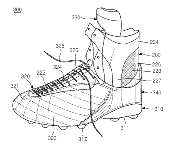
[9] Taking activity into consideration, attempts have been made to develop
semi-
boot-style athletic footwear. For example, Korean U.M. Apple. No. 1998-5838
and
Korean U.M. Apple. No. 2003-16830 have been proposed. The U.M. Apple. No.
1998-5838 was filed by the inventor of this invention, and is titled "ATHLETIC
FOOTWEAR HAVING IMPROVED SAFETY AND LIFE SPAN". Further, the U.M.
Apple. No. 2003-16830 was filed by the inventor of this invention, and is
titled
"ATHLETIC FOOTWEAR HAVING ANKLE PROTECTOR".
[ 10] In addition, the semi-boot-style athletic footwear has been proposed in
Japanese
U.M. Laid-Open Publication No. Sho 57-34804 which is titled "ATHLETIC
FOOTWEAR", U.S. Patent No. 5,430,960 which is titled "LIGHTWEIGHT
ATHLETIC SHOE WITH FOOT AND ANKLE SUPPORT SYSTEMS" and U.S.
Patent No. 5,943,793 which is titled "SHOE OR BOOT WITH ADJUSTABLE
ANKLE COLLAR".
[ 11 ] The above-mentioned semi-boot-style athletic footwear includes an ankle
protecting
part, which extends from an upper end of a heel section to a leg portion above
the
wearer's ankle joint, and is worn to surround the leg portion above the ankle
joint.
[ 12] Although the conventional semi-boot-style athletic footwear is provided
with
various means to afford unrestricted motion to a wearer, the semi-boot-style
athletic
footwear other than basketball shoes does not appeal to consumers.
[13] In order to reduce the danger of injury, an ankle protector of FIG. 1 has
come onto
the market. Many athletes frequently put on footwear with such an ankle
protector on.
[ 14] However, the ankle protector 100 merely surrounds a leg portion
extending from
the heel of the foot to a portion above the ankle joint. That is, the ankle
protector 100 is
separate from the footwear, so that the ankle protector 100 may move relative
to the
footwear without constraint.
[15] Therefore, although a person wears the ankle protector 100, the wearer's
ankle joint
may be excessively twisted, rotated, or bent, due to force exerted on the
footwear.
[16] Further, Korean U.M. Apple. No. 1989-5433 discloses an ankle protector,
which is
attached to footwear and worn, and is titled "ATHLETIC FOOTWEAR WITH
DETACHABLE ANKLE PROTECTOR".
[ 17] The conventional ankle protector is configured such that it is fastened
to an upper
end of a heel section of a shoe using a zipper. When the ankle protector is
fastened to
the shoe, the shoe assumes the shape of the conventional semi-boot-style
athletic
footwear.
Disclosure of Invention
CA 02559325 2006-09-11
3
WO 2005/087030 PCT/KR2005/000741
Technical Problem
[ 18] Accordingly, the present invention has been made keeping in mind the
above
problems occurring in the prior art, and an object of the present invention is
to provide
an ankle support, which is attached to a sole in the interior of footwear and
is worn to
surround a leg portion above the wearer's ankle joint.
[19] Another object of the present invention is to provide footwear having the
ankle
support which is attached to the sole in the interior of the footwear.
[20] A further object of the present invention is to provide footwear having
an in-
teraction means which engages or cooperates with an attaching means that is
provided
on a lower end of the ankle support so as to attach the ankle support to the
sole in the
interior of the footwear.
Technical Solution
[21] According to this invention, an ankle support is attached to a sole.
However, it is
unnecessary to attach the ankle support directly to the sole. That is, all or
part of the
ankle support may be attached to a heel section or an upper which is coupled
to the
sole. Such attachment does not limit the spirit and scope of this invention.
Therefore, it
is to be understood that the expression used in the preferred embodiment as
well as in
the claims, "the ankle support is attached to the sole" includes both direct
attachment
and indirect attachment.
[22] In the case of indirect attachment, it is preferable that the ankle
support be attached
as close to the sole as possible. However, in the case in which the ankle
support is
attached to a position distant from the sole, this must be considered as one
embodiment
of this invention.
[23] In order to accomplish the above objects, the present invention provides
an ankle
support secured to an interior of footwear and worn to surround part of a foot
and part
of a leg between which an ankle joint is located.
[24] The ankle support includes an attaching means provided on a lower end of
the ankle
support and attaching the ankle support to the interior of the footwear, a leg
covering
means constructed such that at least part of the ankle support surrounds a leg
portion
above the wearer's ankle joint, and a support means provided between the leg
covering
means and the attaching means, the support means preventing the wearer's foot
from
moving about the ankle joint beyond a predetermined range.
[25] The support means may include at least one reinforcing strip. The
reinforcing strip
comprises a first strip part arranged along a wearer's Achilles' tendon to
couple the leg
covering means to the attaching means, a second strip part located over a
wearer's
inside malleolus to couple the leg covering means to the attaching means, and
a third
strip part located over a wearer's outside malleolus to couple the leg
covering means to
CA 02559325 2006-09-11
4
WO 2005/087030 PCT/KR2005/000741
the attaching means.
[26] The leg covering means may include a strip which is coupled to an upper
end of the
support means to surround the leg portion above the wearer's ankle joint.
[27] Further, footwear of this invention includes an ankle support which is
attached to a
sole in the interior of the footwear, and is worn to surround part of the foot
and part of
the leg between which the ankle joint is positioned.
[28] A leg covering means of the ankle support is constructed such that at
least part of
the ankle support surrounds a leg portion above the wearer's ankle joint.
[29] A support means, extending from the lower portion of the ankle support
secured to
the footwear to the leg covering means, prevents the wearer's foot from moving
about
the ankle joint beyond a predetermined range.
[30] The support means may include at least one reinforcing strip. The
reinforcing strip
may comprise a first strip part arranged along a wearer's Achilles' tendon and
extending from the lower portion secured to the footwear to the leg covering
means, a
second strip part located over a wearer's inside malleolus to extend to the
leg covering
means, and a third strip part located over a wearer's outside malleolus to
extend to the
leg covering means.
[31] An aerating part may be provided between the first, second and third
strip parts to
allow air to flow in and out of the footwear.
[32] The leg covering means may include a strip which is coupled to an upper
end of the
support means to surround the leg portion above the wearer's ankle joint.
[33] The upper includes a toe top to cover wearer's toes, a first vamp to
cover an inside
portion of a top side of the foot, a second vamp to cover an outside portion
of the top
side of the foot, and a tongue coupled at an end thereof to the toe top, and
covering the
top side of the foot.
[34] At least part of the ankle support may be secured to the heel section,
the first vamp,
or the second vamp of the footwear.
[35] The tongue includes a heat dissipation part, the heat dissipation part
extending
upwards from a position where a wearer's ankle bends, and dissipating heat
from the
interior of the footwear. The tongue includes a pair of extension parts, the
extension
parts extending outwards from both sides of the heat dissipation part and
being secured
to the interior of the footwear.
[36] At least part of each of the extension parts comprises an elastic band
having
elasticity. Each of the extension parts is secured to the interior of the
footwear while
being positioned between an inside surface of the footwear and an outside
surface of
the ankle support.
[37] The footwear may further include a vamp tightening unit to pull a side
end of the
first vamp and a side end of the second vamp, thus allowing the side ends of
the first
CA 02559325 2006-09-11
5
WO 2005/087030 PCT/KR2005/000741
and second vamps to approach each other.
[38] The leg covering means of the ankle support is cut at a position ranging
from the
top side of the foot to a shinbone, and a tightening unit is provided at the
cut position
to pull both ends of the leg covering means, thus causing the ends of the leg
covering
means to approach each other.
[39] A first end of the cut leg covering means is continuously connected to
the side end
of the first vamp, and a second end of the cut leg covering means is
continuously
connected to the side end of the second vamp.
[40] In order to accomplish the above objects, the present invention provides
a footwear
having a sole, an upper, and a heel section, wherein an attaching means for
attaching
an ankle support to the footwear is positioned in the footwear, the ankle
support being
worn to surround part of a foot and part of a leg between which the ankle
joint is
positioned.
Advantageous Effects
[41] According to the present invention, the wearer's ankle joint moves
together with an
ankle support without being constrained by footwear, thus ensuring the
flexible
movement of the ankle, therefore allowing unrestricted motion. Further,
according to
this invention, a lower portion of the ankle support is attached to an
interior of the
footwear, thus allowing the wearer's ankle to be supported by both the
footwear and
the ankle support, therefore efficiently supporting the ankle, even when large
forces are
applied to the ankle due to intense activity.
[42] Particularly, when this invention is adapted to athletic footwear, the
ankle support
of this invention prevents the wearer's ankle from being bent due to external
forces or
wearer's carelessness, thus efficiently protecting the ankle joint joining the
ankle to the
foot and various ligaments, such as the Achilles' tendon, in addition to
allowing the
wearer's ankle to freely move. Therefore, the wearer can enjoy desired sports
without
worrying about injuring the ankle.
Brief Description of the Drawings
[43] FIG. 1 is a perspective view of a conventional ankle protector;
[44] FIG. 2 is a perspective view of an ankle support to be attached to
footwear,
according to an embodiment of the present invention;
[45] FIG. 3 is a perspective view to schematically show the state where a
wearer's foot is
fitted into the ankle support of FIG. 2;
[46] FIG. 4 is a development figure of the ankle support of FIG. 3;
[47] FIG. 5 is a perspective view showing a soccer shoe to which the ankle
support of
this invention is adapted, with part of the soccer shoe not yet laced up;
[48] FIG. 6 is a perspective view showing the soccer shoe of FIG. 5, in which
the soccer
CA 02559325 2006-09-11
WO 2005/087030 PCT/KR2005/000741
shoe is completely laced up;
[49] FIG. 7 is a sectional view taken along line A-A of FIG. 6, showing part
of the
soccer shoe; and
[50] FIG. 8 is a plan view to show the tongue of the soccer shoe of FIG. 5.
Best Mode for Carrying Out the Invention
[51] Hereinafter, an ankle support and footwear with the ankle support,
according to the
preferred embodiment of this invention, will be described with reference to
the ac-
companying drawings.
[52] FIG. 2 is a perspective view of an ankle support to be attached to
footwear,
according to an embodiment of the present invention, FIG. 3 is a perspective
view to
schematically show the state where a wearer's foot is fitted into the ankle
support of
FIG. 2, and FIG. 4 is a development figure of the ankle support of FIG. 3.
[53] As shown in FIGS. 2 to 4, an ankle support 200 of this invention is
configured so
that the ankle support 200 is attached to a sole in the interior of a general
shoe not
extending above the ankle, and extends upwards from a heel section of the
footwear to
surround a leg portion above the ankle joint. That is, the ankle support 200
is attached
to the sole (e.g. an upper surface of a midsole) in the interior of the
footwear. Thus, an
attaching means 210 is provided on a lower portion of the ankle support 200 to
attach
the ankle support 200 to the sole in the interior of the footwear. The
attaching means
210 may have any shape, as long as the attaching means 210 attaches the ankle
support
200 to the sole. It is preferable to further include an additional attaching
member, such
as a Velcro fastener. In this case, part of the attaching means 210 may be
opened. Al-
ternatively, the attaching means 210 may be completely closed. FIG. 2 shows
the
attaching means 210 which is partly opened.
[54] Further, the ankle support 200 is provided with an ankle support part
220. The
attaching means 210 is attached to the sole in the interior of the footwear,
while the
ankle support part 220 extends upwards from the heel section to surround part
of the
foot and part of the leg between which the wearer's ankle joint is positioned,
thus
supporting the ankle. The ankle support part 220 includes a leg covering means
and a
support means. In this case, the leg covering means is configured to surround
a leg
portion above the wearer's ankle joint. The support means is provided between
the leg
covering means and the attaching means 210, thus preventing the wearer's foot
from
moving about the ankle joint beyond a predetermined range.
[55] A foot insertion hole 221 is formed on an upper end of the ankle support
part 220 to
allow the wearer's foot to be inserted into the ankle support part 220.
Further, an
opening 222 is provided at a predetermined position on the ankle support part
220 such
that the wearer's foot may be conveniently inserted into the ankle support
part 220. In
CA 02559325 2006-09-11
WO 2005/087030 PCT/KR2005/000741
this case, the ankle support part 220 may be made of one kind of material to
have a
single structure. Alternatively, the ankle support part 220 may be made of
different
kinds of materials. In this case, different parts are sewn to each other to
provide the
ankle support part 220.
[56] The ankle support part 220 also includes a tightening unit which closes
the opening
222 provided at a predetermined position on the ankle support part 220, thus
allowing
the ankle support 200 to be in close contact with the wearer's ankle. The
tightening unit
may comprise a plurality of eyelets that are formed on both sides of the ankle
support
part 220 and a general shoelace lacing the footwear. Further, the tightening
unit may
comprise a Velcro fastener which is provided on both sides of the ankle
support part
220. Furthermore, the tightening unit may comprise a slide fastener which is
sewn
along both side ends of the ankle support part 220. In addition, the
tightening unit may
comprise a belt which has a buckle and a punch hole on respective sides of the
ankle
support part 220. The tightening unit may comprise a combination of the above-
mentioned elements.
[57] When the ankle support 200 of this invention is adapted to general
footwear, the
ankle support part 220 is preferably configured to prevent foreign objects
from
entering the interior of the footwear through the opening 222. Thus, it is
preferable that
the ankle support part 220 further include a tongue (not shown). The tongue is
secured
at an end thereof to an inside surface of the ankle support part 220, and is
large enough
to cover the opening 222. Preferably, the tongue of the ankle support part 220
is made
such that the lower part of the tongue overlaps part of the tongue of the
footwear.
Further, an additional member may be provided on the tongue of the ankle
support part
220 to be attached to the tongue of general footwear.
[58] Further, the ankle support part 220 may be constructed to be larger than
the size of
the wearer's ankle so as to prevent foreign objects from entering the
footwear. In other
words, if the ankle support part 220 adapted to general footwear is larger
than the
wearer's ankle, the wearer's ankle can be completely covered by overlapping
both sides
of the ankle support part 220.
[59] Meanwhile, the ankle support 200 of this invention may be constructed
such that
the ankle support 200 is closed without the opening 222. In this case, part of
the ankle
support part 220 may comprise an elastic member having elasticity, or the
entire part
of the ankle support part 220 may comprise an elastic member.
[60] As such, the ankle support 200 of this invention is constructed so that
the lower
portion of the ankle support 200 is attached to the interior of the footwear,
unlike the
prior art, thus moving relative to the footwear within a predetermined range.
Therefore,
the footwear having the ankle support 200 of this invention moves together
with the
ankle support 200 without restricting the motion of the wearer's ankle joint
in the
CA 02559325 2006-09-11
8
WO 2005/087030 PCT/KR2005/000741
footwear, thus ensuring the flexible movement of the ankle, therefore allowing
un-
restricted motion. Further, the footwear having the ankle support 200 of this
invention
is constructed so that the lower portion of the ankle support 200 is secured
to the
interior of the footwear. Thereby, even though large shocks are applied to the
wearer's
ankle due to intense activity, the wearer's ankle is protected by both the
footwear and
the ankle support 200, thus allowing the wearer's ankle to be efficiently
protected.
[61] The preferred embodiment of the ankle support according to this invention
will be
described below in detail.
[62] As shown in FIGS. 2 to 4, the ankle support 200 of this invention is made
of
different kinds of materials. These parts are sewn to be combined with each
other. The
tightening unit includes eyelets and a shoelace. In a detailed description,
the foot
insertion hole 221 and the opening 222 are formed on the top and the front of
the ankle
support part 220, respectively. The ankle support part 220 includes the leg
covering
means and the support means. The leg covering means surrounds a leg portion
above
the ankle joint, and the support means prevents the wearer's foot from moving
about
the ankle joint beyond a predetermined range.
[63] The leg covering means includes a strip 224 which is coupled to the upper
end of
the support means and surrounds the leg portion above the wearer's ankle
joint.
[64] Further, the support means includes an aerating part 223 and a
reinforcing strip. The
aerating part 223 is provided at a position around the heel section to allow
air to flow
in and out of the footwear. The reinforcing strip functions to partially
reinforce the
wearer's ankle. The aerating part 223 dissipates heat generated in the
footwear, as a
person moves or exercises with the footwear on, in addition to allowing
exterior fresh
air to circulate in the footwear. The aerating part 223 is made of a soft
material
permitting ventilation. It is preferable that the aerating part 223 extend
upwards from a
lower end to a predetermined height.
[65] Further, the reinforcing strip comprises a first strip part 225, a second
strip part 226,
and a third strip part 227. The first strip part 225 is arranged along the
wearer's
Achilles' tendon to couple the strip 224 of the leg covering means to the
attaching
means 210. The second strip part 226 is located on the wearer's inside
malleolus to
couple the strip 224 to the attaching means 210. Further, the third strip part
227 is
located on the wearer's outside malleolus to couple the strip 224 to the
attaching means
210. In this case, the reinforcing strip may have at least one each first,
second, third
strip part 225, 226, 227. The reinforcing strip serves as tape to massage the
muscular
nerves so as to prevent the muscular nerves of the feet from being abruptly
relaxed or
contracted before a person exercises. Such a reinforcing strip is preferably
made of the
same hard material as footwear, such as leather.
[66] When the strip 224 and the first, second, and third strip parts 225, 226,
and 227 are
CA 02559325 2006-09-11
9
WO 2005/087030 PCT/KR2005/000741
developed, they form the shape of an "m". As such, the ankle support 220
surrounds
and supports the wearer's ankle, and efficiently protects the ankle joint,
joining the
ankle to the foot, and various ligaments, including the Achilles' tendon,
using the
elements constituting the reinforcing strip.
[67] Meanwhile, the ankle support part 220 has a plurality of folding parts
228 that is
naturally folded when the wearer's ankle bends forwards, thus increasing the
range of
motion of the wearer's ankle. That is, the ankle support part 220 is
constructed so that
both sides thereof are uneven, thus forming a plurality of folding parts 228.
Further,
tightening parts 229 are provided on an upper end of the ankle support part
220 to
protrude upwards, thus efficiently fastening the ankle support 200 to the
wearer's
ankle. The tightening parts 229 are connected to both ends of the strip 224.
Further, a
plurality of eyelets 230 is formed on the ankle support part 220, with a
shoelace 325
passing through the eyelets 230 to connect both sides of the opening 222 to
each other.
[68] The footwear with the ankle support according to this invention will be
described
below with reference to soccer shoes, as an example of the footwear. However,
this
invention is not limited to soccer shoes, but is applicable to various
footwear, such as
athletic footwear for various sports including soccer, basketball, tennis,
baseball, rugby
football, badminton, skating, volleyball, etc., work footwear, safety
footwear,
mountain-climbing footwear, or military footwear. That is, when the ankle
support of
this invention is adapted to shoes not extending above the wearer's ankle, it
is un-
necessary to adjust the height of the shoe. Meanwhile, when the ankle support
of this
invention is adapted to boots extending higher than the wearer's ankle, the
ankle
support is inserted into the boot after lowering the height of the boot below
the ankle.
[69] FIG. 5 is a perspective view showing a soccer shoe to which the ankle
support of
this invention is adapted, with part of the soccer shoe not yet laced up, FIG.
6 is a
perspective view showing the soccer shoe of FIG. 5, in which the soccer shoe
is
completely laced up, and FIG. 7 is a sectional view taken along line A-A of
FIG. 6,
showing part of the soccer shoe.
[70] As shown in FIG. 5 to 7, the soccer shoe 300 includes a sole 310, an
upper 320, and
a heel section 340, with an ankle support being attached to the soccer shoe
300. The
ankle support extends upwards from the heel section to surround part of the
foot and
part of the leg between which the ankle joint is positioned, while the lower
portion of
the ankle support is secured to the sole in the interior of the soccer shoe.
[71] The sole 310 includes an outsole 311 on which a plurality of anti-slip
studs 312 is
formed. Further, a middle sole 313 is provided on the outsole 311 to be
integrated with
the outsole 311.
[72] The upper 320 includes a toe top 321 to cover the wearer's toes, a first
vamp 322 to
cover the inside portion of the top side of the foot, a second vamp 323 to
cover the
CA 02559325 2006-09-11
10
WO 2005/087030 PCT/KR2005/000741
outside portion of the top side of the foot, and a tongue 330. The tongue 330
is
connected at an end thereof to the toe top 321 and covers the top side of the
foot.
Further, the upper 320 includes a vamp tightening unit which pulls side ends
of the
first and second vamps 322 and 323 so that the side end of the first vamp 322
approaches the side end of the second vamp 323. In this case, the vamp
tightening unit
includes a plurality of eyelets and a shoelace 325. The eyelets are formed on
eyelet
tabs 326 which are provided on the side ends of the first and second vamps 322
and
323. The shoelace 325 passes through the eyelets. However, the vamp tightening
unit
is not limited to the above-mentioned structure. The vamp tightening unit may
be man-
ufactured like the tightening unit of the ankle support.
[73] The ankle support 200 is manufactured as described above. That is, the
ankle
support 200 is constructed such that the lower portion of the ankle support
200 is
secured to the sole in the interior of the soccer shoe, and the ankle support
200 extends
upwards along the heel section 340 to surround part of the foot and part of
the leg
between which the wearer's ankle joint is positioned.
[74] The soccer shoe 300 of FIGS. 5 to 7 is provided with the ankle support
200
constructed as shown in FIGS. 2 to 4. However, the attaching means 210,
provided on
the lower portion of the ankle support 200, is attached between the outsole
311 and the
midsole 313. That is, the ankle support 200 is constructed so that the leg
covering
means is cut at a position ranging from the top side of the foot to the
shinbone. At the
cut position, both ends of the leg covering means are pulled to approach each
other
using the tightening unit. The attaching means 210 of the ankle support 200
may be
attached to the heel section 340, the first vamp 322, or the second vamp 323.
[75] According to this invention, the first end of the cut leg covering means
may be con-
tenuously connected to the side end of the first vamp 322, and the second end
of the cut
leg covering means may be continuously connected to the side end of the second
vamp
323.
[76] FIG. 8 is a plan development figure showing a tongue of the soccer shoe
of FIG. 5.
As shown in FIG. 8, the tongue 330 serves to prevent foreign objects from
entering the
interior of the shoe. The tongue 330 is sewn at an end thereof to the inside
surface of a
slit 324, and covers the slit 324 and the opening 222 of the ankle support
200.
[77] The tongue 330 includes a slit covering part 331, an opening covering
part 332, and
a lace locking part 333. The slit covering part 331 is sewn at an end thereof
to the
inside surface of the slit 324 to cover the slit 324. The opening covering
part 332 is
connected to the slit covering part 331 to cover the opening 222. The lace
locking part
333 is folded at an end of the opening covering part 332 to be attached to the
upper
surface of the opening covering part 332, thus preventing the shoelace from un-
desirably becoming untied.
CA 02559325 2006-09-11
11
WO 2005/087030 PCT/KR2005/000741
[78] Preferably, the junction between the slit covering part 331 and the
opening covering
part 332 is located at the position where the wearer's ankle bends. More
preferably,
notches 334 are formed on both sides of the tongue 330 to allow the tongue 330
to be
easily folded, in addition to ensuring flexible motion of the ankle. The
notches 334
achieve the same effect as the folding parts 228 of the ankle support part
220.
[79] The opening covering tongue 332 includes a heat dissipation part 335 and
a pair of
extension parts 336. The heat dissipation part 335 serves to dissipate heat
from the
interior of the shoe. The extension parts 336 protrude outwards from both
sides of the
heat dissipation part 335 to define the notches 334, and are attached to the
sole so that
the tongue 330 is located on the top side of the wearer's foot. Preferably,
the heat
dissipation part 335 extends upwards from the junction between the slit
covering part
331 and the opening covering part 332, namely, from the position where the
wearer's
ankle bends. It is preferable that an elastic band 337 having elasticity be
provided at a
predetermined position on each extension part 336, thus allowing the tongue
330 to
conveniently move. Further, it is more preferable that the extension parts 336
be
attached to the sole in the shoe while being positioned between the inside of
the shoe
and the outside of the ankle support 200. Such a construction allows a person
to con-
veniently wear the shoe. FIG. 8 shows the case where the elastic band 337 is
provided
on an end of each extension part 336.
[80] The lace locking part 333 is folded at an upper end of the opening
covering part
332, and is attached to the upper surface of the heat dissipation part 335
using a
fastening unit, thus preventing the shoelace from becoming untied. The
fastening unit
comprises a first piece 338 of the Velcro fastener provided on the upper
surface of the
heat dissipation part 335, and a second piece 339 of the Velcro fastener
provided on
the lower surface of the lace locking part 333. In this case, only an end of
the first
piece 338 is attached to the upper surface of the opening covering part 332 so
that the
first piece 338 does not affect the shoelace 325, thus allowing the opening
covering
part 332 to bend freely. On the other hand, the second piece 339 is completely
secured
to the lace locking part 333.
[81]
[82]
CA 02559325 2006-09-11