Language selection

Search

Patent 2559335 Summary

Third-party information liability

Some of the information on this Web page has been provided by external sources. The Government of Canada is not responsible for the accuracy, reliability or currency of the information supplied by external sources. Users wishing to rely upon this information should consult directly with the source of the information. Content provided by external sources is not subject to official languages, privacy and accessibility requirements.

Claims and Abstract availability

Any discrepancies in the text and image of the Claims and Abstract are due to differing posting times. Text of the Claims and Abstract are posted:

  • At the time the application is open to public inspection;
  • At the time of issue of the patent (grant).
(12) Patent Application: (11) CA 2559335
(54) English Title: BASE OF THE SUNSHADE UMBRELLA
(54) French Title: BASE DE PARASOL
Status: Deemed Abandoned and Beyond the Period of Reinstatement - Pending Response to Notice of Disregarded Communication
Bibliographic Data
(51) International Patent Classification (IPC):
  • A45B 25/00 (2006.01)
  • E04H 12/22 (2006.01)
  • E04H 15/28 (2006.01)
  • F16M 11/22 (2006.01)
(72) Inventors :
  • NENGSEN, CHEN (China)
(73) Owners :
  • CHEN NENGSEN
(71) Applicants :
  • CHEN NENGSEN (China)
(74) Agent: SMART & BIGGAR LP
(74) Associate agent:
(45) Issued:
(22) Filed Date: 2006-09-08
(41) Open to Public Inspection: 2007-04-08
Examination requested: 2008-09-03
Availability of licence: N/A
Dedicated to the Public: N/A
(25) Language of filing: English

Patent Cooperation Treaty (PCT): No

(30) Application Priority Data:
Application No. Country/Territory Date
200520015353.5 (China) 2005-10-08

Abstracts

English Abstract


The present utility model is a large-sized sunshade umbrella which
is used at fixed site outdoor. The interior of the base is divided into
several independent portions, a protection case which is mated with the
base is brought to cover the base, and the devices of caster wheel which
can be stretched-out and drawn-back are provided in the holes at the
corners of the base. Sand or water as the counterweight in the base can
be added or reduced freely. When the base needs to fix, the caster wheels
are drawn-back into the base through manual regulation to make the
base rest on the ground to increase the attaching force; when the
umbrella needs to move, the four caster wheels are stretched-out from
the base to contact with the ground, so that a man or woman can push
the umbrella smoothly to the site where he or she intends to place it.


Claims

Note: Claims are shown in the official language in which they were submitted.

7
Claims
1. A base of sunshade umbrella, characterized in that the interior of the
base is divided into several independent portions, a protection case
which is mated with the base is brought to cover over the base, and
devices of caster wheel which can be stretched-out and drawn-back are
provided in the holes at the corners of the base.
2. The base of sunshade umbrella according to claim 1, characterized
in that said device of caster wheel which can be stretched-out and
drawn-back comprises a lead screw, a holder of lead screw and a caster
wheel, the caster wheel is fixed to the lead screw, the lead screw is
thread-engaged with its holder, and the holder of lead screw is fixed to
the base.
3. The base of sunshade umbrella according to claim 2, characterized
in that said caster wheel comprises a fixing frame, a retainer ring, a
plurality of steel balls, a riveted member, a positioning plate and a wheel,
based on the fixing frame, the upper steel balls are provided in the
annular groove on the fixing frame, and the lead screw is inserted into
the center hole of the fixing frame; the lower steel balls are supported by
the positioning plate, and the wheel is rotatably fixed in the notch of the
fixing frame with the riveted member as a shaft which is retained with
the retaining ring at its tail.
4. The base of sunshade umbrella according to claim 1 or 2,
characterized in that the link rod is linked to the upper end of the lead
screw, and the rotating handle is connected to the link rod.
5. The base of sunshade umbrella according to claim 1 or 2,
characterized in that the holes for lead screw on the protection case are
covered with caps.

Description

Note: Descriptions are shown in the official language in which they were submitted.


CA 02559335 2006-09-08
1
Base of Sunshade Umbrella
Technical Field
The present utility model relates to a large-sized sunshade umbrella
used at fixed site outdoor, in particular, to a base of the sunshade
umbrella.
Background Art
A large-sized sunshade umbrella used at fixed site outdoor, in
particular a pendent umbrella, has very poor steadiness, because its
umbrella face is so large as to catch wind easily. In order to steady an
umbrella as a whole, its base must be very heavy in weight or have a
large counterweight. A base of sunshade umbrella with a conventional
structure has some problems, for example, its counterweight can not be
regulated arbitrarily to make the base difficult to be attached to the
ground more firmly; the umbrella as a whole is too heavy to move at
will, etc.
Summary
The object of the present utility model is to overcome the defects of
the prior art and provide a base of umbrella, as a result, not only its
counterweight can be regulated arbitrarily to make the base preferably
attached to the ground, but also the umbrella as a whole can be move

CA 02559335 2006-09-08
2
easily.
In order to achieve the object, the technical solution of the present
utility model is a base of umbrella, characterized in that the interior
thereof is divided into several independent portions, a protecting case
which is mated with the base is brought to cover it over, and the devices
of caster wheel which can be stretched-out and drawn-back are provided
in the holes at the corners of the base.
Said device of caster wheel which can be stretched-out and
drawn-back comprises a lead screw, a holder of lead screw and a caster
wheel, the caster wheel is fixed to the Iead screw, the Iead screw is
thread-engaged with its holder, and the holder of lead screw is fixed to
the base.
Said caster wheel comprises a fixing frame, a retainer ring ( i * i~
T 1~7 ) , a plurality of steel balls, a riveted member, a positioning
plate and a wheel. Based on the fixing frame, the upper steel balls are
provided in the annular groove on the fixing frame, and the lead screw is
inserted into the center hole of the fixing frame; the lower steel balls are
supported by the positioning plate, and the wheel is rotatably fixed in the
notch of the fixing frame with the riveted member as a shaft which is
retained with the retaining ring at its tail.
A link rod is linked to the upper end of the lead screw, and a

CA 02559335 2006-09-08
3
rotating handle is connected to the link rod.
Four caps are used to cover the holes for the lead screws on the
protection case.
The advantageous effects of the present utility model are as follows:
sand or water as the counterweight of the base can be added or reduced
freely; when the base needs to fix, the caster wheels are drawn-back into
the base through manual regulation so as to make the base rest on the
ground to increase the attaching force; when the umbrella needs to move,
the four caster wheels are stretched-out from the base to contact with the
ground, so that a man or woman can push the umbrella smoothly to the
site where he or she intends to place it.
Brief Description of Drawings
An embodiment of the present utility model will be described in
detail in conjunction with the drawings.
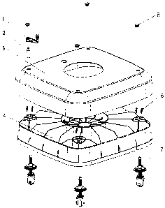
Fig. l is a general structural diagram of the present utility model.
Fig.2 is an exploded view of the regulating device for caster wheel.
In these drawings, the reference numbers as follows
1 rotating handle
2 link rod
3 protecting case for base
4 base
caps

CA 02559335 2006-09-08
4
6 bolts and nuts
7 caster wheels
8 lead screw ( i~i~ : ~ ~~~~ 8 , T~-~ 8 ~:~~~~~
9 holder for lead screw
fixing frame
11 retaining ring
12 steel balls
13 riveted member
14 positioning plate
wheel
Detail Description of Preferred Embodiment
As shown in drawings, a through-hole for insertion of the umbrella
pole is provided in the center of the rectangular base 4, with the hole as a
center, the interior of base 4 is divided radially into several independent
portions, and four through-holes for caster wheels are provided at the
corners of base 4; a through-hole for insertion of the umbrella pole is
provided in the center of protection case 3 which is mated with base 4,
four through-holes for insertion of link rod 2 are provided at the corners,
and protection case 3 is brought to cover over base 4. Holder 9 of lead
screw has the female thread which is engaged with lead screw 8, so that

CA 02559335 2006-09-08
lead screw 8 is screwed into its holder 9, and each of these four holders
9 of lead screw is fixed to base 4 by four sets of socket cap bolts and
nuts which pass through the holes on holder 9, so that it can bear the
heavy burden of 100Kg; then lead screw 8 with a caster wheel is inserted
to the corresponding hole on base 4, thereafter, the independent portions
of base 4 are filled with a certain amount of sand or water as required,
finally, protection case 3 is brought to cover base 4, and caps 5 are
brought to cover the respective holes on case 3.
The device 7 of caster wheel which can be stretched-out and
drawn-back is composed of the caster wheel assemblies such as lead
screw 8, fixing frame 10, retaining ring 11, riveted member 13,
positioning plate 14, wheel 15, etc. Based on fixing frame 10, upper
steel balls 12 are provided in annular groove on fixing frame 10, lead
screw 8 is inserted into the center hole of fixing frame 10, so that the
flange at its lower end is pressed against upper steel balls 12; lower steel
balls 12 are supported by positioning plate 14 which is fixed to the lower
end of lead screw 8, wheel 15 is positioned in the rectangular notch of
fixing frame 10 with riveted member 13 as a shaft which passes through
the center hole, and the riveted member 13 is retained with retaining ring
11 at its tail.
During being used, when base 4 needs to move, the procedure is as
follows: removing caps 5 from protection case 3, inserting link rod 2
into hex-hollow-head at upper end of lead screw 8, putting rotating

CA 02559335 2006-09-08
6
handle 1 around link rod 2 and rotating it in clockwise direction until
caster wheel 7 is stretched-out from base 4 by sufficient distance, and
doing such for all of four caster wheels 7 to make them on the same
plane, in this way, the umbrella with the base can be pushed smoothly.
When the umbrella reaches the desired site, handle 1 and link rod 2 are
rotated in counterclockwise direction until all of four caster wheels 7 are
drawn-back into base 4, so that base 4 can be fixed firmly on the ground
by the aid of the weight of sand or water in its several independent
portions.
One of the preferred embodiments of the present utility model has
been described in the above, however, it should be apparent for those
skilled in the art that various variations and improvements can be done
without departure from the principle of the present utility model when
they fall in the scope defined by the appendant claims.

Representative Drawing
A single figure which represents the drawing illustrating the invention.
Administrative Status

2024-08-01:As part of the Next Generation Patents (NGP) transition, the Canadian Patents Database (CPD) now contains a more detailed Event History, which replicates the Event Log of our new back-office solution.

Please note that "Inactive:" events refers to events no longer in use in our new back-office solution.

For a clearer understanding of the status of the application/patent presented on this page, the site Disclaimer , as well as the definitions for Patent , Event History , Maintenance Fee  and Payment History  should be consulted.

Event History

Description Date
Application Not Reinstated by Deadline 2012-03-23
Inactive: Dead - No reply to s.30(2) Rules requisition 2012-03-23
Deemed Abandoned - Failure to Respond to Maintenance Fee Notice 2011-09-08
Inactive: Abandoned - No reply to s.30(2) Rules requisition 2011-03-23
Inactive: S.30(2) Rules - Examiner requisition 2010-09-23
Letter Sent 2008-10-23
All Requirements for Examination Determined Compliant 2008-09-03
Request for Examination Requirements Determined Compliant 2008-09-03
Request for Examination Received 2008-09-03
Application Published (Open to Public Inspection) 2007-04-08
Inactive: Cover page published 2007-04-08
Inactive: IPC removed 2007-03-15
Inactive: First IPC assigned 2007-03-15
Inactive: IPC assigned 2007-03-15
Inactive: IPC assigned 2007-03-05
Filing Requirements Determined Compliant 2006-10-13
Inactive: Filing certificate - No RFE (English) 2006-10-13
Application Received - Regular National 2006-10-11
Amendment Received - Voluntary Amendment 2006-09-08

Abandonment History

Abandonment Date Reason Reinstatement Date
2011-09-08

Maintenance Fee

The last payment was received on 2010-08-11

Note : If the full payment has not been received on or before the date indicated, a further fee may be required which may be one of the following

  • the reinstatement fee;
  • the late payment fee; or
  • additional fee to reverse deemed expiry.

Please refer to the CIPO Patent Fees web page to see all current fee amounts.

Fee History

Fee Type Anniversary Year Due Date Paid Date
Application fee - standard 2006-09-08
MF (application, 2nd anniv.) - standard 02 2008-09-08 2008-09-02
Request for examination - standard 2008-09-03
MF (application, 3rd anniv.) - standard 03 2009-09-08 2009-09-01
MF (application, 4th anniv.) - standard 04 2010-09-08 2010-08-11
Owners on Record

Note: Records showing the ownership history in alphabetical order.

Current Owners on Record
CHEN NENGSEN
Past Owners on Record
None
Past Owners that do not appear in the "Owners on Record" listing will appear in other documentation within the application.
Documents

To view selected files, please enter reCAPTCHA code :


To view images, click a link in the Document Description column. To download the documents, select one or more checkboxes in the first column and then click the "Download Selected in PDF format (Zip Archive)" or the "Download Selected as Single PDF" button.

List of published and non-published patent-specific documents on the CPD .

If you have any difficulty accessing content, you can call the Client Service Centre at 1-866-997-1936 or send them an e-mail at CIPO Client Service Centre.


Document
Description 
Date
(yyyy-mm-dd) 
Number of pages   Size of Image (KB) 
Description 2006-09-08 6 210
Abstract 2006-09-08 1 27
Claims 2006-09-08 1 53
Drawings 2006-09-08 2 40
Representative drawing 2007-03-26 1 11
Cover Page 2007-03-30 2 46
Filing Certificate (English) 2006-10-13 1 159
Reminder of maintenance fee due 2008-05-12 1 114
Acknowledgement of Request for Examination 2008-10-23 1 190
Courtesy - Abandonment Letter (R30(2)) 2011-06-15 1 165
Courtesy - Abandonment Letter (Maintenance Fee) 2011-11-03 1 173
Fees 2010-08-11 1 34
Prosecution correspondence 2006-09-08 10 329