Sélection de la langue

Search

Sommaire du brevet 2559335 

Énoncé de désistement de responsabilité concernant l'information provenant de tiers

Une partie des informations de ce site Web a été fournie par des sources externes. Le gouvernement du Canada n'assume aucune responsabilité concernant la précision, l'actualité ou la fiabilité des informations fournies par les sources externes. Les utilisateurs qui désirent employer cette information devraient consulter directement la source des informations. Le contenu fourni par les sources externes n'est pas assujetti aux exigences sur les langues officielles, la protection des renseignements personnels et l'accessibilité.

Disponibilité de l'Abrégé et des Revendications

L'apparition de différences dans le texte et l'image des Revendications et de l'Abrégé dépend du moment auquel le document est publié. Les textes des Revendications et de l'Abrégé sont affichés :

  • lorsque la demande peut être examinée par le public;
  • lorsque le brevet est émis (délivrance).
(12) Demande de brevet: (11) CA 2559335
(54) Titre français: BASE DE PARASOL
(54) Titre anglais: BASE OF THE SUNSHADE UMBRELLA
Statut: Réputée abandonnée et au-delà du délai pour le rétablissement - en attente de la réponse à l’avis de communication rejetée
Données bibliographiques
(51) Classification internationale des brevets (CIB):
  • A45B 25/00 (2006.01)
  • E04H 12/22 (2006.01)
  • E04H 15/28 (2006.01)
  • F16M 11/22 (2006.01)
(72) Inventeurs :
  • NENGSEN, CHEN (Chine)
(73) Titulaires :
  • CHEN NENGSEN
(71) Demandeurs :
  • CHEN NENGSEN (Chine)
(74) Agent: SMART & BIGGAR LP
(74) Co-agent:
(45) Délivré:
(22) Date de dépôt: 2006-09-08
(41) Mise à la disponibilité du public: 2007-04-08
Requête d'examen: 2008-09-03
Licence disponible: S.O.
Cédé au domaine public: S.O.
(25) Langue des documents déposés: Anglais

Traité de coopération en matière de brevets (PCT): Non

(30) Données de priorité de la demande:
Numéro de la demande Pays / territoire Date
200520015353.5 (Chine) 2005-10-08

Abrégés

Abrégé anglais


The present utility model is a large-sized sunshade umbrella which
is used at fixed site outdoor. The interior of the base is divided into
several independent portions, a protection case which is mated with the
base is brought to cover the base, and the devices of caster wheel which
can be stretched-out and drawn-back are provided in the holes at the
corners of the base. Sand or water as the counterweight in the base can
be added or reduced freely. When the base needs to fix, the caster wheels
are drawn-back into the base through manual regulation to make the
base rest on the ground to increase the attaching force; when the
umbrella needs to move, the four caster wheels are stretched-out from
the base to contact with the ground, so that a man or woman can push
the umbrella smoothly to the site where he or she intends to place it.

Revendications

Note : Les revendications sont présentées dans la langue officielle dans laquelle elles ont été soumises.


7
Claims
1. A base of sunshade umbrella, characterized in that the interior of the
base is divided into several independent portions, a protection case
which is mated with the base is brought to cover over the base, and
devices of caster wheel which can be stretched-out and drawn-back are
provided in the holes at the corners of the base.
2. The base of sunshade umbrella according to claim 1, characterized
in that said device of caster wheel which can be stretched-out and
drawn-back comprises a lead screw, a holder of lead screw and a caster
wheel, the caster wheel is fixed to the lead screw, the lead screw is
thread-engaged with its holder, and the holder of lead screw is fixed to
the base.
3. The base of sunshade umbrella according to claim 2, characterized
in that said caster wheel comprises a fixing frame, a retainer ring, a
plurality of steel balls, a riveted member, a positioning plate and a wheel,
based on the fixing frame, the upper steel balls are provided in the
annular groove on the fixing frame, and the lead screw is inserted into
the center hole of the fixing frame; the lower steel balls are supported by
the positioning plate, and the wheel is rotatably fixed in the notch of the
fixing frame with the riveted member as a shaft which is retained with
the retaining ring at its tail.
4. The base of sunshade umbrella according to claim 1 or 2,
characterized in that the link rod is linked to the upper end of the lead
screw, and the rotating handle is connected to the link rod.
5. The base of sunshade umbrella according to claim 1 or 2,
characterized in that the holes for lead screw on the protection case are
covered with caps.

Description

Note : Les descriptions sont présentées dans la langue officielle dans laquelle elles ont été soumises.

CA 02559335 2006-09-08
1
Base of Sunshade Umbrella
Technical Field
The present utility model relates to a large-sized sunshade umbrella
used at fixed site outdoor, in particular, to a base of the sunshade
umbrella.
Background Art
A large-sized sunshade umbrella used at fixed site outdoor, in
particular a pendent umbrella, has very poor steadiness, because its
umbrella face is so large as to catch wind easily. In order to steady an
umbrella as a whole, its base must be very heavy in weight or have a
large counterweight. A base of sunshade umbrella with a conventional
structure has some problems, for example, its counterweight can not be
regulated arbitrarily to make the base difficult to be attached to the
ground more firmly; the umbrella as a whole is too heavy to move at
will, etc.
Summary
The object of the present utility model is to overcome the defects of
the prior art and provide a base of umbrella, as a result, not only its
counterweight can be regulated arbitrarily to make the base preferably
attached to the ground, but also the umbrella as a whole can be move

CA 02559335 2006-09-08
2
easily.
In order to achieve the object, the technical solution of the present
utility model is a base of umbrella, characterized in that the interior
thereof is divided into several independent portions, a protecting case
which is mated with the base is brought to cover it over, and the devices
of caster wheel which can be stretched-out and drawn-back are provided
in the holes at the corners of the base.
Said device of caster wheel which can be stretched-out and
drawn-back comprises a lead screw, a holder of lead screw and a caster
wheel, the caster wheel is fixed to the Iead screw, the Iead screw is
thread-engaged with its holder, and the holder of lead screw is fixed to
the base.
Said caster wheel comprises a fixing frame, a retainer ring ( i * i~
T 1~7 ) , a plurality of steel balls, a riveted member, a positioning
plate and a wheel. Based on the fixing frame, the upper steel balls are
provided in the annular groove on the fixing frame, and the lead screw is
inserted into the center hole of the fixing frame; the lower steel balls are
supported by the positioning plate, and the wheel is rotatably fixed in the
notch of the fixing frame with the riveted member as a shaft which is
retained with the retaining ring at its tail.
A link rod is linked to the upper end of the lead screw, and a

CA 02559335 2006-09-08
3
rotating handle is connected to the link rod.
Four caps are used to cover the holes for the lead screws on the
protection case.
The advantageous effects of the present utility model are as follows:
sand or water as the counterweight of the base can be added or reduced
freely; when the base needs to fix, the caster wheels are drawn-back into
the base through manual regulation so as to make the base rest on the
ground to increase the attaching force; when the umbrella needs to move,
the four caster wheels are stretched-out from the base to contact with the
ground, so that a man or woman can push the umbrella smoothly to the
site where he or she intends to place it.
Brief Description of Drawings
An embodiment of the present utility model will be described in
detail in conjunction with the drawings.
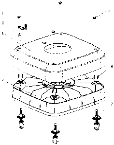
Fig. l is a general structural diagram of the present utility model.
Fig.2 is an exploded view of the regulating device for caster wheel.
In these drawings, the reference numbers as follows
1 rotating handle
2 link rod
3 protecting case for base
4 base
caps

CA 02559335 2006-09-08
4
6 bolts and nuts
7 caster wheels
8 lead screw ( i~i~ : ~ ~~~~ 8 , T~-~ 8 ~:~~~~~
9 holder for lead screw
fixing frame
11 retaining ring
12 steel balls
13 riveted member
14 positioning plate
wheel
Detail Description of Preferred Embodiment
As shown in drawings, a through-hole for insertion of the umbrella
pole is provided in the center of the rectangular base 4, with the hole as a
center, the interior of base 4 is divided radially into several independent
portions, and four through-holes for caster wheels are provided at the
corners of base 4; a through-hole for insertion of the umbrella pole is
provided in the center of protection case 3 which is mated with base 4,
four through-holes for insertion of link rod 2 are provided at the corners,
and protection case 3 is brought to cover over base 4. Holder 9 of lead
screw has the female thread which is engaged with lead screw 8, so that

CA 02559335 2006-09-08
lead screw 8 is screwed into its holder 9, and each of these four holders
9 of lead screw is fixed to base 4 by four sets of socket cap bolts and
nuts which pass through the holes on holder 9, so that it can bear the
heavy burden of 100Kg; then lead screw 8 with a caster wheel is inserted
to the corresponding hole on base 4, thereafter, the independent portions
of base 4 are filled with a certain amount of sand or water as required,
finally, protection case 3 is brought to cover base 4, and caps 5 are
brought to cover the respective holes on case 3.
The device 7 of caster wheel which can be stretched-out and
drawn-back is composed of the caster wheel assemblies such as lead
screw 8, fixing frame 10, retaining ring 11, riveted member 13,
positioning plate 14, wheel 15, etc. Based on fixing frame 10, upper
steel balls 12 are provided in annular groove on fixing frame 10, lead
screw 8 is inserted into the center hole of fixing frame 10, so that the
flange at its lower end is pressed against upper steel balls 12; lower steel
balls 12 are supported by positioning plate 14 which is fixed to the lower
end of lead screw 8, wheel 15 is positioned in the rectangular notch of
fixing frame 10 with riveted member 13 as a shaft which passes through
the center hole, and the riveted member 13 is retained with retaining ring
11 at its tail.
During being used, when base 4 needs to move, the procedure is as
follows: removing caps 5 from protection case 3, inserting link rod 2
into hex-hollow-head at upper end of lead screw 8, putting rotating

CA 02559335 2006-09-08
6
handle 1 around link rod 2 and rotating it in clockwise direction until
caster wheel 7 is stretched-out from base 4 by sufficient distance, and
doing such for all of four caster wheels 7 to make them on the same
plane, in this way, the umbrella with the base can be pushed smoothly.
When the umbrella reaches the desired site, handle 1 and link rod 2 are
rotated in counterclockwise direction until all of four caster wheels 7 are
drawn-back into base 4, so that base 4 can be fixed firmly on the ground
by the aid of the weight of sand or water in its several independent
portions.
One of the preferred embodiments of the present utility model has
been described in the above, however, it should be apparent for those
skilled in the art that various variations and improvements can be done
without departure from the principle of the present utility model when
they fall in the scope defined by the appendant claims.

Dessin représentatif
Une figure unique qui représente un dessin illustrant l'invention.
États administratifs

2024-08-01 : Dans le cadre de la transition vers les Brevets de nouvelle génération (BNG), la base de données sur les brevets canadiens (BDBC) contient désormais un Historique d'événement plus détaillé, qui reproduit le Journal des événements de notre nouvelle solution interne.

Veuillez noter que les événements débutant par « Inactive : » se réfèrent à des événements qui ne sont plus utilisés dans notre nouvelle solution interne.

Pour une meilleure compréhension de l'état de la demande ou brevet qui figure sur cette page, la rubrique Mise en garde , et les descriptions de Brevet , Historique d'événement , Taxes périodiques et Historique des paiements devraient être consultées.

Historique d'événement

Description Date
Demande non rétablie avant l'échéance 2012-03-23
Inactive : Morte - Aucune rép. dem. par.30(2) Règles 2012-03-23
Réputée abandonnée - omission de répondre à un avis sur les taxes pour le maintien en état 2011-09-08
Inactive : Abandon. - Aucune rép dem par.30(2) Règles 2011-03-23
Inactive : Dem. de l'examinateur par.30(2) Règles 2010-09-23
Lettre envoyée 2008-10-23
Toutes les exigences pour l'examen - jugée conforme 2008-09-03
Exigences pour une requête d'examen - jugée conforme 2008-09-03
Requête d'examen reçue 2008-09-03
Demande publiée (accessible au public) 2007-04-08
Inactive : Page couverture publiée 2007-04-08
Inactive : CIB enlevée 2007-03-15
Inactive : CIB en 1re position 2007-03-15
Inactive : CIB attribuée 2007-03-15
Inactive : CIB attribuée 2007-03-05
Exigences de dépôt - jugé conforme 2006-10-13
Inactive : Certificat de dépôt - Sans RE (Anglais) 2006-10-13
Demande reçue - nationale ordinaire 2006-10-11
Modification reçue - modification volontaire 2006-09-08

Historique d'abandonnement

Date d'abandonnement Raison Date de rétablissement
2011-09-08

Taxes périodiques

Le dernier paiement a été reçu le 2010-08-11

Avis : Si le paiement en totalité n'a pas été reçu au plus tard à la date indiquée, une taxe supplémentaire peut être imposée, soit une des taxes suivantes :

  • taxe de rétablissement ;
  • taxe pour paiement en souffrance ; ou
  • taxe additionnelle pour le renversement d'une péremption réputée.

Veuillez vous référer à la page web des taxes sur les brevets de l'OPIC pour voir tous les montants actuels des taxes.

Historique des taxes

Type de taxes Anniversaire Échéance Date payée
Taxe pour le dépôt - générale 2006-09-08
TM (demande, 2e anniv.) - générale 02 2008-09-08 2008-09-02
Requête d'examen - générale 2008-09-03
TM (demande, 3e anniv.) - générale 03 2009-09-08 2009-09-01
TM (demande, 4e anniv.) - générale 04 2010-09-08 2010-08-11
Titulaires au dossier

Les titulaires actuels et antérieures au dossier sont affichés en ordre alphabétique.

Titulaires actuels au dossier
CHEN NENGSEN
Titulaires antérieures au dossier
S.O.
Les propriétaires antérieurs qui ne figurent pas dans la liste des « Propriétaires au dossier » apparaîtront dans d'autres documents au dossier.
Documents

Pour visionner les fichiers sélectionnés, entrer le code reCAPTCHA :


Pour visualiser une image, cliquer sur un lien dans la colonne description du document. Pour télécharger l'image (les images), cliquer l'une ou plusieurs cases à cocher dans la première colonne et ensuite cliquer sur le bouton "Télécharger sélection en format PDF (archive Zip)" ou le bouton "Télécharger sélection (en un fichier PDF fusionné)".

Liste des documents de brevet publiés et non publiés sur la BDBC .

Si vous avez des difficultés à accéder au contenu, veuillez communiquer avec le Centre de services à la clientèle au 1-866-997-1936, ou envoyer un courriel au Centre de service à la clientèle de l'OPIC.


Description du
Document 
Date
(aaaa-mm-jj) 
Nombre de pages   Taille de l'image (Ko) 
Description 2006-09-08 6 210
Abrégé 2006-09-08 1 27
Revendications 2006-09-08 1 53
Dessins 2006-09-08 2 40
Dessin représentatif 2007-03-26 1 11
Page couverture 2007-03-30 2 46
Certificat de dépôt (anglais) 2006-10-13 1 159
Rappel de taxe de maintien due 2008-05-12 1 114
Accusé de réception de la requête d'examen 2008-10-23 1 190
Courtoisie - Lettre d'abandon (R30(2)) 2011-06-15 1 165
Courtoisie - Lettre d'abandon (taxe de maintien en état) 2011-11-03 1 173
Taxes 2010-08-11 1 34
Correspondance de la poursuite 2006-09-08 10 329