Note: Descriptions are shown in the official language in which they were submitted.
CA 02559710 2006-09-12
WO 2005/107547 PCT/SE2004/000700
1
A DISPENSER FOR INDIVIDUAL FOLDED WEBS
TECHNICAL FIELD
This invention generally relates the field of dispensing devices and systems.
More particularly, this invention relates to the field of devices and systems
for
dispensing folded sheets of material.
BACKGROUND ART
Dispensers for individual folded webs such as paper napkins are often
provided at quick service food locations and restaurants. One disadvantage
of many conventional paper napkin dispensers is that they often provide
rather poor single feed dispensing of folded napkins. Such inadequate single
feed dispensing can be particularly noticeable if the napkins are individual
folded napkins (e.g., conventional overfold napkins) instead of interfolded
napkins. Another disadvantage is that both conventional overfold napkin
dispensers and interfolded napkin dispensers often permit removal of
multiple napkins at one time. As a rule, most paper napkins removed in this
manner are wasted unnecessarily. Many end up scattered about an eating
area, on tables or are merely discarded as litter. When multiple of napkins
are removed in this way dispensers quickly run out and must be refilled,
which is an inconvenience for both customers and operators of quick service
food locations and restaurants.
Common problems with conventional overfold paper napkins have been
described in, for example, WO 98/40002. Conventional overfold paper
napkins are designed to be stacked in a napkin dispenser such as, for
example, a spring loaded napkin dispenser or a gravity feed dispenser. Such
napkin dispensers have an opening revealing an open end of an outermost
napkin facing the opening. In this position, a user can grab an exposed
section of a napkin to pull the napkin out of the dispenser.
However, when stacked improperly with the wrong end of the napkin facing
the opening, dispensing is awkward, and often results in wastage. Not
CA 02559710 2010-12-02
26516-112
2
uncommonly, maintenance personnel will stack overfold paper napkins
improperly, or stack too many napkins thereby overfilling the dispenser.
The invention is aimed at achieving an improved dispenser avoiding problems
relating to the feeding out and presenting of individual folded webs. The
invention
is further aimed at avoiding problems relating to wasteful dispensing in
dispensers
for individual folded or interfolded webs.
DISCLOSURE OF INVENTION
Embodiments disclosed herein provide a dispenser for individual webs from a
stack of such individual webs.
According to one aspect of the present invention, the dispensing face has a
front
portion projecting out from the dispenser, wherein a cross-section through
said
face has a general S-shape with an inflection point that will be described in
more
detail below. Preferably, the dispensing opening is located about an
inflection
point on or an inflection line across the front surface in an area, preferably
but not
necessarily, adjacent a central portion of the face.
The definition of an inflection point is a point on a curve at which the sign
of the
curvature (i.e., the concavity) changes. Inflection points may be stationary
points,
but are not relative maxima or relative minima. For example, for the curve y =
x3
plotted in Figure 1, for one embodiment of a dispenser, the point x = 0 is an
inflection point. Usually, a so called first derivative test may distinguish
inflection
points from extrema for differentiable functions f(x). However, the shape of
the
dispensing face is neither limited to follow any particular mathematical
function,
nor to symmetrical on either side of the inflection point. A number of
examples will
be described in detail below.
According to a preferred embodiment, the invention relates to a dispenser for
individual webs from a stack of such individual webs, the dispenser
comprising: an
outer housing defining an interior space; stacking means mounted within the
outer
housing for holding a stack of individual folded
CA 02559710 2006-09-12
WO 2005/107547 PCT/SE2004/000700
3
webs within the interior space; a dispensing face defined in the outer housing
proximate to an end of the stacking means; a stack of individual folded webs
having an area of non-uniform thickness across the length of the web aligned
so that an area of greatest thickness extends across the width of a
dispensing opening; and at least one edge of the dispensing opening which
contacts the stack of individual folded webs so that a portion of the stack of
individual folded webs is exposed by the dispensing opening. A cross-section
through said dispensing face, in a plane parallel to the direction of feed of
the
webs and at substantially right angles to an exposed edge or fold across the
web, has a curved shape with at least one inflection point. An individual web
to be dispensed through said opening will be pushed forwards to conform to
the rear surface of the dispensing face.
The shaped dispensing face causes the main part of the web to assume the
same shape, at least in the areas surrounding the dispensing opening. By
indexing the dispensing opening with an exposed edge or fold across the
web, a user may remove the outermost web by gripping said edge or fold. By
positioning the edge or' fold over an outwardly convex section of the
dispensing face, this part of the web will assume a presentation position
away from the plane of the main body of the web to facilitate removal of
single webs in succession. The convex section of the dispensing face facing
the user forms part of the outermost end section of the dispenser.
According to one example, the cross-section through the dispensing face
may be given a general, or approximate S-shape.
In a further embodiment, inflection points are provided in successive cross-
sections through the dispensing face across at least a part of the entire
width
of said face. By joining the successive inflection points the point would
appear to be located in a line across or adjacent the dispensing opening.
According to an alternative embodiment, a line of inflection points are
provided in successive cross-sections through the dispensing face on either
CA 02559710 2006-09-12
WO 2005/107547 PCT/SE2004/000700
4
side of the dispensing opening. In this case the inflection points would
appear
to be located in an imaginary line across the dispensing opening.
In both the above embodiments the inflection points may be located in a line
positioned in a plane substantially parallel to an outer wall of the housing.
Such an outer wall would normally be one of the side walls to which the
dispensing face or its stacking means is secured. This wall is as a rule
located in a substantially horizontal plane, although a vertically arranged
wall
is possible. The stacking means may comprise a drawer section to which the
dispensing face is attached, wherein the folded webs are stacked in the
drawer section.
In an alternative embodiment, the inflection points may be located in a line
positioned at an angle to a plane parallel to an outer wall of the housing.
In a further alternative embodiment, the inflection points may be located on a
curved, convex line across the entire width of the dispensing face. This
curved line may follow a radius, to give a constant curvature across the
entire
width of the dispensing face. Alternatively it may follow a part of an
elliptic
curve, to give variable curvature across said face.
According to a further alternative, the curved line may also have a constant
or variable curvature across at least a part of the dispensing face,
preferably
coinciding with at least a part of the dispensing opening. Such a curved line
may be located either symmetrically or offset relative to a centreline through
the dispenser housing in a horizontal plane.
For the above embodiments describing inflection points located on a curved,
convex line, the dispenser face is assumed to have a generally S-shaped
cross section in a vertical plane. According to one embodiment, the curvature
curved, convex line may be constant for substantially all cross-sections in a
horizontal plane.
Alternatively, the curvature of the curved line may vary in the horizontal
direction, whereby a maximum value for the curvature of said line coincides
with the line of inflection points and/or the general area of the exposed edge
CA 02559710 2010-12-02
26516-112
of the folded web. Consequently, the respective upper and lower edges of
the dispensing face may have a maximum value for the curvature and/or be
in the shape of a straight line.
The stack of individual folded webs to be dispensed by the system according
5 to the invention is preferably, but not necessarily, a stack of fibrous
webs.
Preferably, the stack of folded webs is a stack of absorbent paper webs such
as, for example, absorbent paper napkins.
According to a further preferred embodiment, an edge or fold of an outermost
web exposed by the dispenser opening may be located substantially parallel
with or at least in the general direction of a line of inflection points.
However,
said line of inflection points located at an angle relative to the edge or
fold.
The line may also have the shape of a curve relative to the edge or fold.
Similarly, a stack of individual folded webs having an area of non-uniform
thickness across the length of the web may be aligned so that an area of
greatest thickness of an outermost napkin extends across the width of the
dispensing opening substantially parallel with or at least in the general
direction of a line of inflection points.
For all the above embodiments, said edge or fold should be located across
the convex section of the dispensing face, in a position between the fine of
inflection points and an edge of the dispensing opening. The latter edge is
preferably substantially parallel to said edge or fold of the web, but may
also
be substantially parallel to said line of inflection points. As stated above,
a
sufficient portion of the web must be exposed by the dispensing opening to
ensure that the web will assume a presentation position away from the
general plane of the main body of the web to facilitate removal of single webs
in succession.
CA 02559710 2010-12-02
26516-112
5a
According to another aspect of the present invention, there is provided a
dispenser for individual webs from a stack of such individual webs, the
dispenser
comprising: an outer housing defining an interior space; stacking means
mounted
within the outer housing for holding a stack of individual folded webs within
the
interior space; a dispensing face defined in the outer housing proximate to an
end
of the stacking means; a stack of individual folded webs; and at least one
edge of
a dispensing opening in contact with the stack of individual folded webs so
that a
portion of the stack of individually folded webs is exposed by the dispensing
opening, wherein a cross-section through said face has a curved shape with an
inflection point between a convex curvature and a concave curvature.
According to aspects of the invention as described in the above embodiments
and
the following examples, the dispenser is preferably, but not necessarily,
designed
for dispensing folded sheet products from a stack of individual folded webs.
The
term "individual webs" is defined as including either of individually
CA 02559710 2007-02-14
26516-112
6
stacked webs, overfolded webs or interfolded webs, or similarly arranged
sheet products. The webs may or may not be joined by manually separable
perforations or by a number of local attachment zones or connecting points.
The stack of individual folded webs may be a stack of fibrous webs.
Desirably, the stack of folded webs is a stack of absorbent sheets or webs
such as, for example, absorbent non-woven products. More desirably, the
stack of folded webs is a stack of absorbent fibrous or paper sheets or webs
such as, for example, napkins, towels, tissues or the like.
These and various other advantages and features of novelty which
characterize the invention are pointed out with particularity in the claims
annexed hereto and forming a part hereof. However, for a better
understanding of the invention, its advantages, and the objects obtained by
its use, reference should be made to the drawings which form a further part
hereof, and to the accompanying description of the invention.
BRIEF DESCRIPTION OF DRAWINGS
In the following text, the invention will be described in detail with
reference to
the attached drawings. These drawings are used for illustration only and do
not in any way limit the scope of the invention. In the drawings:
CA 02559710 2007-02-14
26516-112
6a
Figure 1A shows a side view of a dispensing face
for a dispenser according to an embodiment of the invention,
Figure 1B shows an alternative side view of a
dispensing face for a dispenser according to an embodiment
of the invention,
Figure 2 shows a perspective view of a dispenser
according to an embodiment of the invention;
Figure 3A shows a front view of a dispenser
according to Figure 2;
Figure 3B shows an alternative front view of a
dispenser according to Figure 2;
Figure 4A shows an example of a folded web for use
in the dispenser according to an embodiment of the
invention;
Figure 4B shows an alternative example of a folded
web for us in the dispenser according to an embodiment of
the invention;
Figure 5A shows a cross-section in a vertical
plane of one alternative embodiment of the dispenser;
Figure 5B shows a cross-section in a vertical
plane of a further alternative embodiment of the dispenser;
CA 02559710 2006-09-12
WO 2005/107547 PCT/SE2004/000700
7
Figure 6 shows a cross-section of a further alternative embodiment of the
dispenser;
Figure 7 shows a cross-section of a further alternative embodiment of the
dispenser;
Figure 8 shows a schematic cross-section in a horizontal plane of one
alternative embodiment of the dispenser;
Figure 9 shows a schematic cross-section in a horizontal plane of a
further alternative embodiment of the dispenser;
Figure 10 shows a schematic cross-section in a horizontal plane of a
further alternative embodiment of the dispenser;
Figure 11 shows a schematic cross-section in a horizontal plane of a
further alternative embodiment of the dispenser;
Figure 12 shows a schematic cross-section in a horizontal plane of a
further alternative embodiment of the dispenser.
MODES FOR CARRYING OUT THE INVENTION
Figure 1 shows a side view of a dispensing face for a dispenser according to
the invention. By way of example only, the dispenser 1 has been provided
with a dispensing face 2 that in a side view, or in cross-section, has the
approximate shape of a curve defined by the equation y = x3 with an inflection
point 3 in the middle section of the dispensing face 2. The axes x and y
defining the position of the curve, in relation to the front face of the
dispenser,
are located in a horizontal and a vertical plane respectively. This
positioning
of the inflection point 3 gives the dispensing face a concave shape 4 across
the width of the upper part of the face, and a convex shape 5 across the
width of the lower part of the face.
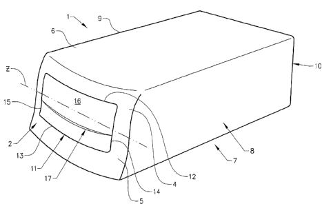
Figure 2 shows a perspective view of a dispenser according to the invention.
The dispenser 1 comprises the dispensing face 2, with its respective upper
and lower sections 4, 5, and a housing made up of an upper wall 6, a bottom
CA 02559710 2006-09-12
WO 2005/107547 PCT/SE2004/000700
8
wall 7, a pair of side walls 8, 9, connecting said upper and lower walls, and
a
rear wall 10 opposite the dispensing face 5.
The dispensing face 5 is provided with a dispensing opening 11 having an
upper and a lower edge 12, 13 and a pair of opposing side edges 14, 15. The
size of the dispensing opening limited by the said edges is smaller than the
size of the web 16 to be dispensed (as indicated in Fig.3). A web pushed
forward by a feeding means, such as a spring (see Fig.5), will contact the
rear side of the curved dispensing face 5 causing the main part of the web to
assume the same shape, at least in the area of the edges surrounding the
dispensing opening. The outermost, exposed web 16 has a fold or edge 17
extending across its entire width, which fold or edge is gripped by a user
wishing to extract a web. The inflection point illustrated in Figure 1 is
indicated as a line z formed by successive cross-sections through the
dispensing face 3 across the entire width of said face. By joining the
successive inflection points the point would appear to be located in a line z,
indicated by a dash-dotted line, across the dispensing opening and the
adjacent sides of the dispensing face 3. The dispensing opening 11, the fold
or edge 17 of the web 16 and the line are arranged so that said fold or edge
17 is located between the line z and the lower edge 13 of the dispensing
opening 11. This places the fold or edge 17 in the convex section 5 of the
dispensing face 3, causing the fold or edge to assume a presentation position
away from the plane of the main body of the web.
Figure 3 shows a front view of a dispenser according to the invention, using
the reference numerals of Figure 2. This figure indicates more clearly how
fold or edge 17 is located between the line z and the lower edge 13 of the
dispensing opening 11. In addition, the approximate location of the outer
edges 18 of the web 16 in relation to the edges 12, 13, 14, 15 of the
dispensing opening 11 are indicated by a dashed line
Figure 4A shows an example of a folded web for use in the dispenser
according to the invention. The individual folded webs are composed of: (a) a
first, central panel; (b) a second panel, unitary with said first panel and
folded
CA 02559710 2006-09-12
WO 2005/107547 PCT/SE2004/000700
9
over a first side of said first panel; (c) a third panel, unitary with the
first
panel, and folded over a second side of the first panel; (d) a fourth panel,
unitary with the second panel, and folded so as to be positioned between the
first and second panels; and (e) a fifth panel, unitary with the third panel,
and
folded so as to be positioned between the first and third panels, such that a
portion of the third panel and fifth panel overlap a portion of the second
panel
and fourth panel generating an area of non-uniform thickness across the
length of the web.
With reference to Figure 4A, the folded web 16 includes a first, central panel
20 that has a first fold line 21 at a first end and a second fold line 22 at a
second end that is opposite from the first end. The folded web 16, further
includes a second panel 23 having a first end that is joined with the first
panel
at the first fold line 21 and a second end having a third fold line 24 defined
thereat. A third panel 25 having a first end that is joined with the first
panel 20
15 at the second fold line 22 further includes a second end having a fourth
fold
line 26 defined thereat. The folded web 16 also includes a fourth panel 27
that is joined to the second panel 23 at the third fold line 24. The fourth
panel
27 is folded with respect to the second panel 23 at the third fold line 24 so
that fourth panel 27 is positioned substantially between the first panel 20
and
20 the second panel 23. Similarly, the folded web 16 includes a fifth panel 28
that is joined to the third panel 25 at the fourth fold line 26. The fifth
panel 28
is folded with respect to the third panel 25 at the fourth fold line 26 so
that the
fifth panel 28 will be positioned substantially between the third panel 25 and
the first panel 20 when folded as described above.
The combined width of the second and third panels 23, 25 are greater than
the width of the first panel 20, which will result in a web product 16 has a
zone or region of non-uniform thickness extending across the length of the
folded web product in a central region when the product is folded flat. The
width of the first panel 20 is defined as being the distance from the first
fold
line 21 to the second fold line 22. The width of the second panel 23 is
defined
as being the distance from the first fold line 21 to the third fold line 24,
and
CA 02559710 2006-09-12
WO 2005/107547 PCT/SE2004/000700
the width of third panel 25 is defined as being the distance from the second
fold line 22 to the fourth fold line 26.
When loaded into a dispenser I according to the invention, a web 16 as
described above will have the folded edge 24 (see edge 17 in Figs.2 & 3)
5 exposed for a user to grip. In the case of the example of Figure 2 and 3,
the
second panel 23 will be in contact with the lower and side edges 13, 14, 15 of
the dispenser opening 11. Due to the shape of the side edges 14, 15 of the
opening 11, the first panel 20 will conform to the general shape of the
dispensing face 2. However, the second panel 23 will only contact the convex
10 section 5 of said dispensing face 2, allowing the second panel 23 and its
folded edge 17, 24 to angle away from the first panel 20 in the region
between the lower edge 13 of the dispensing opening and the line z (shown
in Figs. 2 & 3).
Figure 4B shows an alternative example of a folded web for use in the
dispenser according to the invention. The individual folded webs are
composed of: (a) a first, central panel; (b) a second panel, unitary with said
first panel and folded over a first side of said first panel. With reference
to
Figure 4B, the folded web 16' includes a first, central panel 20' that has a
first
fold line 21' at a first end and a first edge 22' at a second end that is
opposite
from the first end. The folded web 16', further includes a second panel 23'
having a first end that is joined with the first panel 20 at the first fold
line 21'
and a second end having a second edge 24' defined thereat. The folded web
may comprise a single, two or four layers, depending on how it is folded.
Should it comprise two or more layers, then the second edge 24' will instead
be a folded edge. If the web 16' comprises four layers, then the entire length
of one of the side edges, at right angles to the first and second edges 21'
and
24', will also be a folded edge.
Figures 5 to 8 shows a number of examples of a dispenser according to the
invention. With the exception of Figure 8, all these figures are shown in
cross-section in a central vertical plane through a dispenser of the type
shown in Figure 2. The dispensers in the said figures include an outer
CA 02559710 2006-09-12
WO 2005/107547 PCT/SE2004/000700
11
housing 30 defining an interior space 31 that contains a stacking means 32
which is mounted within the outer housing 30 for holding a stack of individual
folded webs (e.g., paper napkins) 16 of the type described above within the
interior space 31.
The dispenser 1 also includes a dispensing face 2 defined in the outer
housing 30 proximate to an end of the stacking means 32. The stacking
means 32 is further provided with a pusher plate 33 acted on by a spring
means 34, for feeding the stack of webs towards the dispensing opening 11.
In Figure 5 the dispensing face 2 has an inflection point 3 located at
approximately half the vertical height of the dispenser 1. The axes x and y
defining the position of the curve the front face of the dispenser are located
in
a horizontal and a vertical plane respectively. This positioning of the
inflection
point 3 gives the dispensing face a concave shape 4 across the width of the
upper part of the face, and a convex shape 5 across the width of the lower
part of the face 2. As can be seen in the figure, the first panel 20 conforms
to
the shape of the dispensing face 2, while the third panel 23 with its folded
edge 24 has separated from the first panel 20. In this example the curve the
front face of the dispenser is substantially symmetrical with respect to the
inflection point.
In Figure 6 the dispensing face 2 has an inflection point 3 located at
approximately two thirds of the vertical height of the dispenser 1. The axes x
and y defining the position of the curve the front face of the dispenser are
located in a horizontal and a vertical plane respectively. As in Figure 5,
this
positioning of the inflection point 3' gives the dispensing face a concave
shape 4' across the width of the upper part of the face, and a convex shape
5' across the width of the lower part of the face 2. Similarly, the first
panel 20'
conforms to the shape of the dispensing face 2, while the third panel 23' with
its folded edge 24' has separated from the first panel 20'. In this example
the
curve the upper and lower sections 4', 5' of the dispensing face 2 are
asymmetric with respect to the inflection point.
CA 02559710 2006-09-12
WO 2005/107547 PCT/SE2004/000700
12
In an alternative embodiment of the example shown in Figure 6, it is possible
to invert the stack of webs. In this case, the second panel would extend from
the upper part of the dispensing opening, past the inflection point, into the
convex part of the lower section of the dispensing face.
In Figure 7 the dispensing face 2 has an inflection point 3" located at
approximately half the vertical height of the dispenser 1. The axes x and y
defining the position of the curve the front face of the dispenser are located
at
an angle a relative to the horizontal and vertical planes respectively. As in
Figure 5, this positioning of the inflection point 3" gives the dispensing
face a
concave shape 4" across the width of the upper part of the face, and a
convex shape 5" across the width of the lower part of the face 2. Similarly,
the first panel 20" conforms to the shape of the dispensing face 2, while the
third panel 23" with its folded edge 24" has separated from the first panel
20". In this example the curve the upper and lower sections 4", 5" of the
dispensing face 2 are symmetrical with respect to the inflection point.
Figure 8 shows a schematic cross-section in or near a central horizontal
plane through the line of inflection points of a dispenser similar to that
shown
in Figure 2. Using the reference numerals of Figure 2, the dispenser is
provided with a pair of side walls 8, 9 enclosing a stack of webs 16. The
dispensing face 2 has a dispensing opening where the side edges 14, 15
have basically the same cross-section in a vertical plane as indicated in
Figures 2 and 5. However, instead of forming a straight line (see "z", Figure
2) the line of inflection points forms a curve C, which curve is convex in the
direction of the user. In the horizontal plane shown in Figure 8, a suitable
angle R between a tangent to the curve C and a vertical, transverse plane
through the dispenser at the point of intersection between the dispensing
face 2 and the side walls 8, 9 is in the range 1-20 , preferably 10-20 .
Figure 9 shows a cross-section in a central horizontal plane through the line
of inflection points of a further embodiment of the dispenser. In this
embodiment, the curvature of the curved line is a constant radius R, having
its centre located on the centreline CL through the dispenser housing. As in
CA 02559710 2006-09-12
WO 2005/107547 PCT/SE2004/000700
13
Figure 8, the angle p is measured between a tangent T to the curve C1 and a
vertical, transverse plane through the dispenser at the point of intersection
between the dispensing face 2 and the side walls 8, 9 According to one
example, the radius R1 of a relatively large dispenser may be selected in the
interval 320-335 mm and the angle R in the interval 15-18 . According to a
further example, the radius R1 of a relatively small dispenser may be selected
in the interval 80-130 mm and the angle R in the interval 23-26 . These radii
and angles are given by way of example only and do not limit the scope of
the invention as claimed.
In a modification of Figure 9, the radius R, may comprise the major axis of an
ellipse, resulting in a curvature that increases with the distance from the
centreline CL through the dispenser housing.
Figure 10 shows a cross-section in a central horizontal plane through the line
of inflection points of a further embodiment of the dispenser. In this
embodiment, the curvature of the curved line has the shape of a partial
ellipse, where the foci F1, F2 of the ellipse are located so that a tangent to
the
largest curvature C2 of the ellipse intersects a vertical plane through one
side
wall 8 and a tangent to the smallest curvature c2 of the ellipse intersects a
vertical plane through the opposite side wall 9.
Figure 11 shows a cross-section in a central horizontal plane through the line
of inflection points of a further embodiment of the dispenser. In this
embodiment, the curvature C3 of the curved line follows an approximate sine
function, varying from a maximum at the centreline CL of the dispenser
housing, where the curve has a radius R3, to a minimum coinciding with the
respective intersection points with vertical planes through the side walls 8,
9.
Figure 12 shows a cross-section in a central horizontal plane through the line
of inflection points of a further embodiment of the dispenser. In this
embodiment, the curvature C4 of the curved line is asymmetric with respect
to the centreline CL. The curvature has a maximum value with a radius R4 at
a location offset a distance a from the centreline. From this point of the
curve,
CA 02559710 2006-09-12
WO 2005/107547 PCT/SE2004/000700
14
the part of the curved line intersecting the centreline follows an approximate
sine function, varying from said maximum to a minimum coinciding with the
intersection point with a vertical plane through the side wall 8. The
remaining
part of the curved line maintains a constant radius R4 to the point of
intersection with a vertical plane through the opposite side wall 9.
The invention is not limited to the examples given above, as the curvature of
the front face in the horizontal plane may be varied freely within the scope
of
the invention.
By providing such a double curvature in the dispensing face 2, it is possible
to facilitate the separation of the folded edge 24 form the first panel 20
(see
Figure 5) even further. For this purpose it is desirable that at least a part
of
the convex section in the vertical plane is intersected by at least part of
the
convex curvature in the horizontal plane near the general area of the line of
inflection points and/or the exposed edge of the folded web.
The present invention preferably, but not necessarily, intended for use with
horizontally placed individual folded paper napkin dispensers, providing
reliable and less wasteful dispensing of individual folded paper napkins.
Depending on the positioning of the stacking arrangement, the dispenser
may also be arranged on its side, that is with the dispensing face and the
stacked webs rotated 90 relative to the stacking means. Of course, the
dispenser of the present invention may be used with vertically mounted
dispensers such as, for example, vertically mounted napkin, tissue or towel
dispensers with a lower dispensing opening.
It is to be understood, however, that even though numerous characteristics
and advantages of the present invention have been set forth in the foregoing
description, together with details of the structure and function of the
invention, the disclosure is illustrative only, and changes may be made in
detail, especially in matters of shape, size and arrangement of parts within
the principles of the invention to the full extent indicated by the broad
general
meaning of the terms in which the appended claims are expressed.