Note: Descriptions are shown in the official language in which they were submitted.
CA 02560099 2006-09-15
WO 2005/099998 PCT/US2005/012701
CLOSURE WITH VENTS FOR VENTING DURING MOLDING
OF A LINER, METHOD OF FORMING A LINER IN A
CLOSURE, AND DEVICE FOR FORMING A LINER IN A CLOSURE
FIELD OF THE INVENTION
The present invention relates to a method and device
for venting gas during molding of a liner in a closure.
BACKGROUND INFORMATION
U.S. Patent No. 4,274,822 refers to an apparatus for
f o rming seal liners of thermoplastic material within closure
cap shells. The apparatus is purported to include a
plurality of movable dies each having an inner die and an
annular outer die, both of which are movable up and down in
re 1 atively slidable relation with each other and arranged so
that the inner die takes itlowermost position after the
out er die has taken its lowermost position. A downward
movement of the outer die is restricted so that a constant
clearance may be maintained between its lower end and an
int ernal surface of a cap shell to be worked with, and so
that an annular foaming chamber of a constant capacity is
formed beneath the lower end of the outer die. A plurality
of gas discharging grooves are provided so as to be
communicated with the foaming chamber.
U.S. Patent No. 5,332,381 refers to an apparatus for
forming liners of thermoplastic material within closure
shells. The apparatus is purported to include a movable die
having an inner punch member and an annular outer mold
member, both of which are moveable up and down in relatively
sli dable relation with each other and arranged so that the
inner punch takes its lowermost position after the outer
mold member has taken its lowermost position. As the inner
punch moves into its lowermost position, thermoplastic
material is forced through radial grooves so that a thick
CA 02560099 2006-09-15
WO 2005/099998 PCT/US2005/012701
annular pad portion of seal liner may form beneath the lower
end wall of' the outer mold member.
U.S. Patent No. 5,800,764 refers to an'ext ernal venting
method for forming a closure liners, in which venting means
are provided by a plurality of venting passages formed in an
outer surface of a liner sleeve of a liner-forming assembly
when properly positioned within the closure. A liner tip
coaxially disposed in the sleeve is advanced to compress a
moldable plastic liner-forming material between the closure,
the liner tip, and the sleeve, so that gas may vent
therefrom to a region external to the sleeve.
SUMMARY
The present invention provides a method and device for
forming a liner in a closure, in which a configuration of
spaced pads or stand-offs in a top wall of the closure may
facilitate venting of air or other gases during compression
molding of a liner material against the top wall. Since the
spaced pads or stand-offs are configured as part of the
closure itself, the liner-molding device used to compress
the liner material may be more flexibly designed for use
with a wide range of closure configurations, and therefore
may need not be re-configured to accommodate vaxying and/or
future closure configurations.
According to an exemplary embodiment of the present
invention, a closure having a top wall, a circurnferential
s%.irt downwardly extending from the top wall, and an outer
band extending from the skirt, includes a series of spaced
pads or stand-offs which form unobstructed spaces or gaps to
vent gas during compression of a liner-forming material by a
liner-molding device. The spaced pads may be a rranged to
engage an outer punch of the liner-molding device so that
gas that would otherwise be trapped between the top wall and
the liner-molding device may escape via the spaces between
2
CA 02560099 2006-09-15
WO 2005/099998 PCT/US2005/012701
the pads. In this regard, the outer punch of the liner-
molding device may have, for example, a flat face.
According to an exemplary method of the present
invention, an axially movable inner punch of the liner-
molding device is arranged with the inner circumference of
the puter punch. During molding of the liner, the outer
punch engages the pads formed in the top wall of the
closure, an amount of moldable material is applied to the
top wall of the closure, and the inner punch is extended to
compress and form the liner from the moldable material.
During compression of the liner, gas that would otherwise be
trapped may be ejected through the gaps formed between the
pads.
In accordance with an example embodiment of the present-
invention, a closure device include a top wall, a skirt
depending from the top wall, and a plurality of pads
arranged circumferentially on the top wall. The pads extend
into a space formed by the top;wall and the skirt, and the
pads are configured'to vent gas between adjacent pairs of.
pads during molding of a liner material against the top
wall.
The pads may be configured to engage a face of an outer
punch of a liner-molding device during compression of the
liner material against the top wall by an axially movable
inner punch of the liner-molding device. The face of the
outer punch may be essentially flat.
The pads may be radially oriented on an inner surf-ace
of the top wall, and the inner surface of the top wall may
be one of circular, oblong, elliptical, parabolic, spiral,
and spherical.
The skirt may include threads configured to interact
with a threaded portion of a container neck.
The closure device may include a tamper indicating band
arranged on the skirt.
3
CA 02560099 2008-04-09
64005-1214
The closure device may be made of one of a rigid and
semi-rigid material, e.g. , plastic, polypropylene, etc.
The closure device may be constructed as a single
piece.
In an example embodirnent of the present invention, a
method of forming a liner in a closure device, includes
applying a moldable materIal to a top wall of the closure
device, engaging a face of a punch of a liner-molding device
with pads arranged on the top wall, the pads extending into
a space formed by the top wall and a skirt depending from
the top wall, compressing the moldable material by the punch
against the top wall to fo rm the liner, and venting gas
between adjacent pairs of pads during the compressing step.
The punch may include a f1 at face. The moldable material
may be compressed in the compressing step against the top
wall by extending an axial ly movable inner punch of the:
liner=molding device. The method may-including forming the
closure device, e.g., by molding, e.g., injection molding.
In an example embodiment ofthe present invention, a
closure includes a top wal 1, a skirt depending from thetop
wall, and venting means arrranged circumferentially on the
top wall for venting gas during molding of a liner material
against the top wall.
In an example embodiinent of the present invention, -a
device for forming a liner in a closure includes means for
applying a moldable materi al to a top wall of the closure
device, means for engaging pads arranged on the top wall,
the pads extending into a space formed by the top wall and a
skirt depending from the top wall, means for compressing the
moldable material against the top wall to form the liner,
and means for venting gas between adjacent pairs of pads
during the compression of the moldable material against the
top wall_
4
CA 02560099 2008-04-09
64005-1214
In an example embodiment of the present invention,
there is a closure device, comprising: a top wall; a skirt
depending from the top wall, the skirt having an inner wall;
a plurality of pads arranged circumferentially on the top
wall, the pads extending into a space formed by the top wall
and the skirt, the space being generally cylindrical with a
central axis extending generally parallel to the skirt and
generally perpendicular to the top wall, the pads having a
first surface extending generally parallel to the axis for
abutting an outer edge of a liner and a second surface
having a first portion generally perpendicular to the first
surface and configured to engage a face of an outer punch of
a liner-molding device during compression of the liner
material against the top wall by an axially movable inner
punch of the liner-molding device and a second portion
forming a transition with the inner wall of the skirt, and
spaces between the pads, the spaces being of a size
sufficient to vent gas that would be trapped between the top
wall and a liner-molding device during molding of a liner
material against the top wall.
In an example embodiment of the present invention,
there is a closure device, comprising: a top wall having an
inner surface and an outer surface; a skirt depending from
the top wall, the skirt having an inner surface and an outer
surface the top wall inner surface and the skirt inner
surface forming a cavity having central axis generally
perpendicular to the central portion of the top wall inner
surface; a plurality of pads arranged circumferentially on
the top wall, the pads extending into the cavity; the pads
having a first surface extending generally parallel to the
axis for abutting an outer edge of a liner and a second
surface having a first portion configured to engage a face
of an outer punch of a liner-molding device during
4a
CA 02560099 2008-04-09
64005-1214
compression of the liner material against the top wall by an
axially movable inner punch of the liner-molding device, the
second surface having a first portion and a second portion,
the first portion being generally perpendicular to the first
surface, and the second portion forming a transition between
the first portion and the inner wall of the skirt, and
spaces between the pads, the spaces being of a size
sufficient to vent gas that would be trapped between the top
wall and a liner-molding device during molding of a liner
material against the top wall.
4b
CA 02560099 2006-09-15
WO 2005/099998 PCT/US2005/012701
BRIEF DESCRIPTION OF THE DRAWYNGS
Figure lA illustrates a perspective view of a closure'
according to an exemplary embodiment of the present
invention.
Figure 2 illustrates a bottom view of the exemplary
closure of Figure 1.
Figure 3A illustrates a c ross-sectional view of the
exemplary closure of Figures L and 2 along designated
section A-A in Figure 2.
Figures 33 illustrates a cross-sectional view of the
exemplary closure of Figures 1 and 2'along designated
sections B-B of Figure 2 during compression of a liner
material using a liner-molding device.
Figure 3C-illustrates a cross-sectional view of the
exemplary closure of Figures 1 and 2 along designated
section C-C of Figure 2 during compress of a line-r material
using a liner-molding device.
. Figure 4 illustrates a cross-sectional view of the
exemplary closure of Figures 1 and 2 engaged with a.liner-
molding device.
Figure 5 illustrates an en.larged cross-sectional view
of the exemplary closure.
DETAILED DESCRIPTION
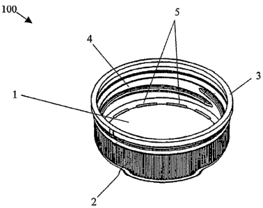
Figures 1 and 2 illustrate a closure 100 according to
an exemplary embodiment of the present invention. In
particular, Figure 1 illustrate s a perspective view of the
closure 100, and Figure 2 illustrates a bottom view of the
closure 100.
Closure 100 includes a top wall 1, a skirt portion 2
depending from the top wall and extending downwardly, and an
outer band 3 arranged on an outer edge of the skirt portion
2. The top wall 1 includes a s e ries of spaced pads or
stand-offs 5 which form gaps 6 that may be used to vent air
or other gases during compression of a liner material
CA 02560099 2006-09-15
WO 2005/099998 PCT/US2005/012701
against the top wall 1. The pads 5 are configured to engage
a liner-molding device during c ompression of a liner
material against the inner surface of the top wall 1 so that
air or other gases that would o therwise be trapped between
the top wall 1 and the liner-mo lding device may escape via
the gaps 6 formed between the pads 5. Accordingly, the
liner-molding device need not be specifically configured to
accommodate the release of the trapped gas.
The pads 5 are illustrated as arranged radially and
evenly spaced around the circumference of the i.nner surface
of the top wall 1. In this regard, the exemplary closure
100 is configured with twelve p ads 5, however, more or fewer
pads 5 may be provided. Other suitable arrangements, pad
spacing, pad location, etc. may also be provided depending
the configuration of the partictilar closure and/or liner-
molding device used to compress the liner material. For
example, the top wall 1 is illu s trated as circular in sh.ape,
although any suitable shape may be provided, including, but
not limited to, oblong, elliptical, parabolic, spiral,
spherical, etc.
The inner sidewall of the skirt portion 2 includes
threads 4 which may interact wit_h a threaded portion of a
container neck to retain the closure on a container. In
this regard, the exemplary closure 100 may be applied, for
example, with standard capping a quipment to glass bottles or
plastic bottles, including those made to standard industry
tolerances and government regula tions.
The outer band 3 may be con figured as a tamper-
indicating band to indicate to a consumer, for example, if
the container has been opened or- otherwise tampered with.
In this regard, the outer band 3 may include extending tabs
and may be frangibly connected to the skirt portion 2 so
that when the closure is removed from a container for the
first time, the tabs contact a shoulder of the container and
cause the outer band 3 to separa t e from the skirt portion 2.
6
CA 02560099 2006-09-15
WO 2005/099998 PCT/US2005/012701
A tab arrangement and tamper-indicating banca, such as that
described, for example, in U.S. Patent No. 6,371,317, which
is expressly incorporated herein in its entz.rety by
reference thereto, may be provided.
The exemplary closure 100 may be made o f any
appropriate rigid or semi-rigid material, irncluding, for
example, hard plastic, polypropylene, etc., and may be
constructed, for example, in one piece using a single
injection molding process. Moreover, the exemplary closure
100 may be suitable for a wide variety of li_ner materials
and/or liner-forming assemblies. For exampLe, the exemplary
closure 100 may be suitable for liner-formirng assemblies
that include flat or smooth faces whose cleanliness and
integrity may be more easily maintained, tha reby improving
overall quality and/or reducing defect rates. The exemplary
closure 100 may also be suitable to accommodate future
innovations in closure and/or liner-forming assembly design
so that such innovations are not unnecessarily restricted or
delayed.
Figure 3A illustrates a cross-sectional view of the
exemplary closure 100 of Figures 1 and 2 tak en along the
line A-A in Figure 2. As illustrated, the arrangement of
pads and gaps arranged on the top wall 1 may not interfere
with other elements of the exemplary closure 100, including,
for example, the skirt portion 2, the outer band 3, and
threads 4. In this regard, elements- of the exemplary
closure 100 may be freely designed to suit o ther and/or
additional requirements. For example, the threads 4 may be
freely designed to accommodate a wide variety of container
connections.
Figures 3B and 3C illustrate cross-secti onal views of
the exemplary closure 100 of Figures 1 and 2 taken along the
lines B-B and C-C of Figure 2 during compression of a liner
material using a liner-molding device. In particular,
Figure 3B illustrates a cross-sectional view of the
7
CA 02560099 2006-09-15
WO 2005/099998 PCT/US2005/012701
exemplary closure 100 taken along t.he line B-B, and Figure
3C illustrates a cross-sectional vL ew of the exemplary
closure 100 taken along the line C-C.
As shown, an outer punch 7 of the liner-molding device
has a flat face arranged to engage the spaced pads 5 during
molding of the liner. An axially mEovable inner punch 8 of
the device is arranged within the inner circumference of
the outer punch 7. During molding of the liner, the outer
punch 7 engages the pads 5 formed in the top wall 1, an
amount of moldable material is applied to the top wall 1,
and the inner punch 8 is extended t o compress and form the
liner from the moldable material. .During compression of the
liner, gas that would otherwise be t rapped between the inner
punch surface 8a, the outer punch 7 , and the top wall 1, is
ejected through gaps 6.
Figure 4 illustrates a cross-sactional view of an
exemplary interaction of the closure 100 of Figures 1 and 2
and a liner-molding device. A gap 6 formed between spaced
pads 5 arranged on the inner surface of the top wall 1 forms
a space for gas to escape during cornpression of a liner
material by the liner-molding device. In particular, pads 5
engage the outer punch 7 and/or innar punch 8 of the liner-
molding device during compression to allow gas to vent
through the gaps 6 that would otherwise be trapped.
Figure 5 illustrates an enlarged cross-sectional view
of the exemplary closure 100. As i3 lustrated in Figure 5,
the pads 5 have a height H from the top wall 1 and extend a
distance D from a central longitudin.al axis of closure 100.
8