Note: Descriptions are shown in the official language in which they were submitted.
CA 02560415 2006-09-19
WO 2005/095230 PCT/US2005/010460
AEROSOL SPRAY
FIELD
The present invention relates to an aerosol spray head, an aerosol spray unit
comprising the aerosol spray head and a process for spraying pressurised
product.
BACKGROUND
One conventional approach to dispensing a product onto a target application
surface is via atomisation of that product. One way of achieving atomisation
is to
combine the product with a propellant (compressed gas) in a pressurized unit
having a
dispensing valve fluidly connected to a dispensing outlet. On opening the
dispensing
valve, the product is forced therethrough and dispensed via the outlet in an
atomized form
onto the target application surface.
The present inventors have established, however, that current atomization
technology generally does not deliver a satisfactory product distribution onto
the target
area. In particular, the distribution is observed to be uneven, with increased
deposition
occurring in the centre and correspondingly reduced deposition towards the
extremities of
the target site. In addition to the uneven spread of active agent and
resulting uneven
achievement of benefit across the target site, high centre deposition may
additionally
result in the formation of unsightly residues and unpleasant cooling in that
region of the
consumer's skin, due to the increased amounts of product deposited there and
increased
amounts propellant evaporating at that location.
In addition to the above-mentioned shortcomings, a single outlet spray head
also
places physical limitations on the composition which may be sprayed. In
particular, high
viscosity compositions may not be practically sprayed, because insufficient
energy may
be retained in such a fluid under typical pressurisation conditions for it to
become
sufficiently atomised on leaving the spray outlet.
With reference to US 3,767,125, a mufti-outlet spray head is proposed for
spraying dry powder aerosols.
With reference to US 5,516,045, an alteunative mufti-outlet spray head is
disclosed, especially for spraying hair lacquer.
It would be advantageous to provide a spray head which overcomes the
disadvantages of spray heads disclosed in the prior art.
CA 02560415 2006-09-19
WO 2005/095230 PCT/US2005/010460
2
Summary
According to a first aspect of the invention a spray head for attachment to an
aerosol container containing pressurised product is provided, the spray head
comprising
at least two separate spray outlets, wherein at least one of the spray outlets
(3) has a non-
circular cross-sectional shape.
According to a second aspect of the invention, an pressurised aerosol spray
unit is
provided, having a spray head as defined in the first aspect of the invention.
According to a third aspect of the invention, a portable pressurised aerosol
spray
unit is provided, having a spray head as defined in the first aspect of the
invention.
According to a fourth aspect of the invention, a process for spraying a
pressurised
product is provided, comprising the steps of spraying said product through a
spray head
according to the first aspect of the invention, such that the product has a
Reynolds
Number of at least 1000 as it leaves said spray outlets.
These and other features, aspects, and advantages of the present invention
will
become evident to those skilled in the art from a reading of the present
disclosure.
BRIEF DESCRIPTION OF THE DRAWINGS
While the specification concludes with claims which pat-ticularly point out
and
distinctly claim the invention, it is believed the present invention will be
better
understood from the following description of preferred embodiments taken in
conjunction
with the accompanying drawings, in which like reference numerals identify
identical
elements and in which:
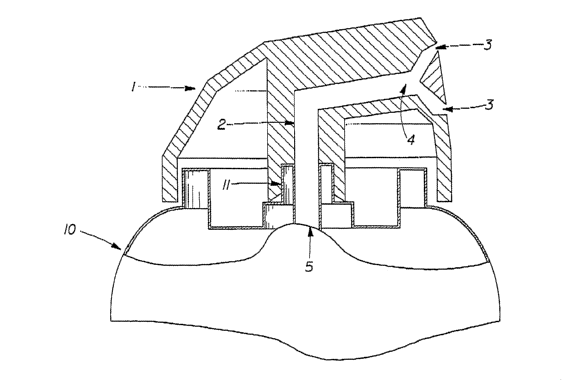
Fig. 1 is a cross-sectional view of a spray head according to the invention
Fig. 2 is an enlarged cross-sectional view of the important parts of a spray
head
according to the invention.
DETAILED DESCRIPTION
While the specification concludes with claims which particularly point out and
distinctly claim the invention, it is believed the present invention will be
better
understood from the following description.
All weights, measurements and concentrations herein are measured at 25oC on
the
composition in its entirety, unless otherwise specified.
CA 02560415 2006-09-19
WO 2005/095230 PCT/US2005/010460
3
Unless otherwise indicated, all percentages of compositions referred to herein
axe
weight percentages of the total composition (i.e. the sum of all components
present) and
all ratios are weight ratios.
Unless otherwise indicated, the content of all literature sources referred to
within
this text are incorporated herein in full by reference.
Except where specific examples of actual measured values are presented,
numerical values referred to herein should be considered to be qualified by
the word
"about".
As has been discussed, a limitation of traditional aerosol spray head
configurations is that they may produce an uneven distribution of product on
the target
site. In addition, the viscosity of the product to be sprayed may be
practically constrained
to remain below a certain level.
By introducing instability into the fluid flow at an early stage it is
possible to
atomize products with greater viscosities and, at the same time, improve the
product
distribution on the target site. The replacement of a single spray outlet by
multiple outlets
may assist in introducing that instability, because, for a given volume flow
of product, the
size of the shear interface (i.e. the total outlet perimeter size) is greater
for multiple
outlets than for a single outlet. The utilisation of one or more non-circular
outlets may
additionally assist in introducing early instability into the flow. Without
wishing to be
bound by theory, it is believed that these measures may prevent the formation
of a
smooth film structure just outside the outlet where the product commences its
trajectory
to the target site. The disadvantage of a smooth film structure is that it may
propagate a
relatively coarse atomization in the final stage before the product reaches
the target site,
with the drops at the center of the spray being larger than those near the
periphery. It is in
the final stage of the spray formation where an instability in the system may
help
disintegrate the product into ligaments and then further into drops to form a
highly
atomised spray and an improved drop distribution.
As defined above, the present invention overcomes the disadvantages of the
prior
art by providing a spray head (1) comprising at least two separate spray
outlets (3),
wherein at least one the spray outlets (3) and advantageously all of the spray
outlets (3)
have a non-circular cross-sectional shape.
CA 02560415 2006-09-19
WO 2005/095230 PCT/US2005/010460
4
As used herein, the term "circle" means a closed plane curve every point of
which
is equidistant from a fixed point within the curve and the word "circular"
shall be
interpreted accordingly.
The spray outlets (3) may have any non-circular shape, but advantageously have
a
cross-sectional shape selected from the group consisting of polygonal, semi-
circular,
crescent, stellate and mixtures thereof. If polygonal, then each polygonal
cross-sectional
shape may advantageously be selected from the group consisting of polygons
having
from three to ten sides. Preferably, the polygons are selected from the group
consisting of
triangular, rectangular, pentagonal, hexagonal and mixtures thereof.
The spray head (1) according to the invention may have any number of spray
outlets (3) above two, but preferably has from 2 to 36 and more preferably
from 3 to 12
spray outlets (3).
The spray head (1), according to the first aspect of the invention may
additionally
comprise a splitting chamber (4) for diverting the flow to the spray outlets
(3), wherein
the conduit means comprise inlet means (5) for attachment to a valve stem (11)
of the
aerosol spray unit and outlet means which are in fluid communication with the
splitting
chamber (4), wherein the splitting chamber (4) is in fluid communication with
the spray
outlets (3).
In this event, and as best shown in Figure 2, the ratio, LllL2, for each spray
outlet
of the distance (L1) between the splitting chamber (4) and the spray outlet
(3) to the
distance (L2) between the inlet means (6) and the spray outlet (3) is
advantageously, in
the range 0.01 to 0.6, more advantageously in the range 0.015 to 0.4 and more
advantageously still in the range 0.02 to 0.4. This is because it is
advantageous to locate
the point at which the flow splits to travel to the two or more separate spray
outlets close
to the spray outlets such that most of the flow in the spray head occurs prior
to the split.
This measure may ensure that the product sprayed is homogenous and may
minimise
differences between the product sprayed from different spray outlets.
In the event that the conduit and/or ducts leading to the spray outlets have a
non-
constant cross-sectional area such that either or both of L1 and L2 may vary
depending
on the line of measurement, then the measurements must be made along the
centre line
connecting the centres of the inlet means (5), the conduit outlet means and
the respective
spray outlet (3).
CA 02560415 2006-09-19
WO 2005/095230 PCT/US2005/010460
According to a second aspect of the invention, an aerosol spray unit (10) is
provided comprising a pressurised product to be dispensed and having a spray
head (1)
according to the first aspect of the invention.
As used herein, the term "spray unit" means a pressurised aerosol canister,
comprising a valve, the valve stem of which extends from the canister,
typically at the
top. Such canisters typically have a volume up to 1000m1, though more
typically at or
below 200m1 and are typically pressurised at 103kPa to 552 kPa (15 to ~Opsi),
more
typically at or Iess than 414 kPa (60psi).
As used herein, the term "product" means all components of the composition or
mixture contained within the spray unit, including all active agents, all
carrier materials
and all propellant.
Preferably, the product to be dispensed is a cosmetic product, more preferably
it is
selected from the group consisting of antiperspirants, deodorants and mixtures
thereof.
If the product to be dispensed is an antiperspirant, then it may comprise
antiperspirant active particulates and a carrier such that the antiperspirant
active
pauticulates are not soluble in the carrier. Alternatively, the antiperspirant
active may be
solubilised in the carrier.
According to a third aspect of the invention, a portable aerosol spray unit
(10) is
provided comprising a pressurised product to be dispensed and a spray head (1)
according to the first aspect of the invention..
As used herein, the term "portable" used in relation to an aerosol spray unit
means
that it may readily be transported in one hand by a single adult person of
ordinary
strength.
According to a fourth aspect of the invention, a process for spraying a
pressurised
product is provided comprising the steps of spraying said product through a
spray head
having at least two separate spray outlets (3), wherein at least one of the
spray outlets (3)
has a non-circular cross-section, such that the product has a Reynolds Number
of at least
3000 as it leaves said spray outlets (3).
It is understood that the examples and embodiments described herein are fox
illustrative purposes only and that various modifications or changes in light
thereof will
be suggested to one skilled in the art without departing from the scope of the
present
invention.
CA 02560415 2006-09-19
WO 2005/095230 PCT/US2005/010460
6
All documents cited in the Detailed Description of the Invention are, in
relevant
part, incorporated herein by reference; the citation of any document is not to
be construed
as an admission that it is prior art with respect to the present invention. To
the extent that
any meaning or definition of a term in this written document conflicts with
any meaning
or definition of the term in a document incorporated by reference, the meaning
or
definition assigned to the term in this written document shall govern.
While particular embodiments of the present invention have been illustrated
and
described, it would be obvious to those skilled in the art that various other
changes and
modifications can be made without departing from the spirit and scope of the
invention.
It is therefore intended to cover in the appended claims all such changes and
modifications that are within the scope of this invention.