Note: Descriptions are shown in the official language in which they were submitted.
CA 02560549 2006-09-18
WO 2005/091528 PCT/US2005/008741
SATELLITE DIVERSITY SYSTEM, APPARATUS
AND METHOD
CROSS-REFERENCES TO RELATED APPLICATIONS
[0001] This application claims the benefit of U.S. Provisional Application No.
60/554,222, filed March 17, 2004; entitled METHOD AND APPARATUS FOR
PROVIDING SATELLITE DIVERSITY, which is hereby incorporated herein by
reference in its entirety.
BACKGROUND OF THE DISCLOSURE
[0002] Communication satellites provide communication support for a wide
region.
Typically the supported region is an area on the surface of the earth that
lies within the
beam of a satellite that is directed towards the earth. The region can be
relatively
stationary such as when the communication satellite is a geostationary
satellite. The
region may vary over time such as when the communication satellite is a low
earth orbit
(LEO) satellite. Some systems may require numerous satellites each having
multiple
beams. Other communication systems may use a single satellite covering a wide
coverage area in a single beam. For example, a communication system may use a
single
communication satellite having a beam that covers a region that includes the
entire
continental United States.
[0003] The reliability of a satellite is of utmost concern because
communication
satellites often are used to provide critical communication linlcs. The remote
nature of a
communication satellite combined with the extended period of time needed to
put a
replacement satellite into space makes the satellite a single point whose
failure can bring
down communication channels for an extended period of time. To alleviate the
single
point failure nature of a communication satellite, communication system
designers often
provide an in-orbit spare satellite in order to maintain the communication
channels in
case the operating satellite fails. The spare satellite is not normally used
for
communications, but is used to provide system redundancy. If the operational
satellite
should fail, the communications are switched to the in-orbit spare in order to
maintain
communications. The failed satellite can then be repaired or decommissioned.
Another
in-orbit spare can then be placed into space to provide a redundant
communication
satellite.
CA 02560549 2006-09-18
WO 2005/091528 PCT/US2005/008741
2
[0004] In satellite communication systems where a single communication
satellite can
support a region as large as the continental United States, the in-orbit spare
represents a
large system cost that provides a disproportionately small benefit. It would
be
advantageous to reduce the system burden of a dormant in-orbit spare.
BRIEF SUMMARY OF THE DISCLOSURE
[0005] A system, apparatus and method for communication diversity using a
plurality
of satellites is disclosed. The satellites can support multiple regions
corresponding to
multiple satellite beams. Each satellite can support all regions in the
reverse direction
and each satellite can be designated as a primary satellite for one of the
multiple regions
corresponding to one of the multiple satellite beams.
[0006] In the reverse linlc direction from, for example, a mobile station to
the satellite,
each satellite can receive from any of the regions reverse link signals
broadcast by the
mobile station. Each satellite can communicate the received reverse link
signals to, for
example, a base station or gateway where the signals can be combined to
increase signal
quality.
[0007] In the forward link direction, the base station or gateway broadcasts a
signal to
a satellite that can be relayed to the mobile station. A mobile station
receives forward
link signals from the primary satellite and monitors a signal quality from the
primary
satellite and from a secondary satellite. If the signal quality from the
primary satellite
drops below a threshold value, the communication signal is transferred to the
secondary
satellite.
[0008] In one aspect, the disclosure includes a satellite diversity system
including a
first satellite configured to provide a first beam as a primary beam
supporting a first
region, a second satellite configured to provide a second beam as a secondary
beam
supporting a region substantially overlapping the first region, and a ground
station . The
ground station is configured to transmit a signal to the first region via the
first satellite
during a period of time when a communication path through the first satellite
is not
degraded, and configured to transmit the signal to the first region via the
second satellite
during the period of time that the communication path through the first
satellite is
degraded.
CA 02560549 2006-09-18
WO 2005/091528 PCT/US2005/008741
3
[0009] In another aspect, the disclosure includes a satellite diversity system
including
a gateway transceiver configured to selectively transmit a forward link signal
to one or
both of a first satellite and a second satellite, a quality of service module
coupled to the
gateway transceiver and configured to determine if a communication path
through the
first satellite is degraded, and a link control module coupled to the quality
of service
module and configured to control the gateway transceiver to transmit the
forward link
signal to the first satellite to be relayed to a mobile station if the
communication path
through the first satellite is not degraded, and configured to control the
gateway
transceiver to transmit the forward link signal to the second satellite to be
relayed to the
mobile station if the communication path through the first satellite is
degraded.
[0010] In still another aspect, the disclosure includes a satellite diversity
system
including a first satellite having a first beam providing coverage for a first
region and a
second beam providing coverage for a second region, the first satellite
configured as a
primary satellite for the first region and a secondary satellite for the
second region, a
second satellite having a first beam providing coverage for a third region
that
substantially overlaps the first region and a second beam providing coverage
for a fourth
region that substantially overlaps the second region, the second satellite
configured as a
primary satellite for the fourth region and a secondary satellite for the
third region, and a
ground station configured to transmit a first signal to a first mobile station
in an
overlapping portion of the first and third regions via the first satellite
when a signal
metric reported by the first mobile station is greater than a predetermined
threshold, and
configured to transmit the first signal to the first mobile station via the
second satellite
when the signal metric is not greater than the predetermined threshold.
[0011] In yet another aspect, the disclosure includes a method of providing
satellite
diversity. The method includes transmitting a signal to a receiver positioned
in a first
geographic region using a first satellite, determining if a communication link
from the
first satellite to the receiver is degraded, and transmitting the signal to
the receiver using
a second satellite if the communication link from the first satellite is
degraded.
CA 02560549 2006-09-18
WO 2005/091528 PCT/US2005/008741
4
BRIEF DESCRIPTION OF THE DRAWINGS
[0012] The features, objects, and advantages of embodiments of the disclosure
will
become more apparent from the detailed description set forth below when taken
in
conjunction with the drawings, in which like elements bear like reference
numerals.
[0013] Figures lA-1B are functional diagrams of satellites having one or more
beams configured to provide area coverage.
[0014] Figure 2 is a functional blocle diagram of an embodiment of a satellite
diversity system.
[0015] Figure 3 is a functional block diagram of an embodiment of a satellite
diversity system.
[0016] Figure 4 is a flowchart of an embodiment of a method of providing
satellite diversity.
[0017] Figure 5 is a flowchart of an embodiment of a method of providing
satellite diversity.
DETAILED DESCRIPTION OF THE DISCLOSURE
[0018] The disclosed system and method of providing diversity in a satellite
communication system can use a plurality of satellites, each satellite having
multiple
beam patterns providing communication support for a corresponding number of
regions.
Each satellite can be configured to be a primary communication satellite for
at least one
of the regions supported by the multiple beams. The beams and satellites are
typically
allocated such that each beam within the aggregate service area has a
satellite assigned
as the primary satellite for that beam. Additionally, for each of the beams, a
satellite
different from the primary satellite is assigned as a secondary satellite for
the region
supported by the beam.
[0019] The satellite communication system can implement different signal
processing
depending on the communication link direction. A forward link direction
typically
refers to a communication link from a stationary base station or gateway to a
mobile
station, and may occur via the satellite. A reverse link direction typically
refers to a
CA 02560549 2006-09-18
WO 2005/091528 PCT/US2005/008741
communication link from the mobile station to the base station or gateway, and
may
also occur via the satellite.
[0020] In the reverse link, each satellite can receive signals from mobile
stations in
one or more of the beams, including beams covering regions for which the
satellite is
not designated as the primary satellite. The satellites can then transmit the
reverse link
communication to the base station or gateway. The base station or gateway can
combine the signals to increase the signal quality. If the reverse link signal
from one of
the mobile stations to one satellite is occluded or somehow degraded, the
reverse link
signal will likely be transmitted by another satellite, ensuring a
communication link
between the mobile station and the base station or gateway. The likelihood is
low that
all of the reverse link signals will be degraded to the extent that the base
station or
gateway is not able to recover the reverse link communication.
[0021] In the forward link direction, the base station or gateway transmits
the forward
link signal to one or more satellites. The primary satellite assigned to the
region having
the mobile station relays the forward link signal to the mobile station.
Typically, the
other satellites do not transmit the forward link signals to the regions for
which the
satellite is not designated the primary satellite. However, the satellites may
continue to
transmit overhead channels, which may include pilot, sync, and paging
channels, to
regions where the satellites are not designated as primary satellites.
[0022] A mobile station receiving the forward link transmissions may determine
a
signal quality of the received signal. The mobile station may also determine
the signal
quality of one or more of the overhead channels transmitted by the non-primary
satellites. The mobile station may report signal quality values back to the
base station
or gateway. For example, the mobile station may report the signal quality
values as part
of a power control loop.
[0023] If the forward linlc signal transmitted by the primary satellite is
degraded, such
as by an obstruction or a degradation in the satellite, the mobile station can
report the
degraded signal quality to the base station. The base station can determine,
based in
part on the signal quality values, if the signal quality transmitted by the
primary satellite
has degraded below an acceptable level. The base station can configure the
secondary
satellite, or one or more of the non-primary satellites, to broadcast the
forward link
CA 02560549 2006-09-18
WO 2005/091528 PCT/US2005/008741
6
signal to the mobile station if the signal quality from the primary satellite
is no longer
acceptable. Thus, the base station can configure a satellite to broadcast a
forward link
signal in a beam for which the satellite is not the primary satellite. The
secondary
satellite can be configured to provide a relatively high probability of
availability.
Therefore, if the forward link signal from the primary satellite is occluded
or otherwise
degraded, the system can switch the forward link signal to the secondary
satellite and
have a high likelihood that the communication link will remain connected.
[0024] Figure lA is a functional diagram of the satellite configuration of a
prior art
satellite communication system 100. The system 100 includes a first
communication
satellite 110 that is configured to provide coverage for a region 112
corresponding to a
beam of an antenna radiation pattern. In some embodiments, the beam may
substantially illuminate a region as large as the continental United States.
Although
shown as a single beam, it is generally understood that a beam can be
implemented as a
plurality of beams collectively illuminating a region substantially equivalent
to a larger
region. Thus, the beam from the first communication satellite 110 can include
a
plurality of beams providing support for the region 112.
[0025] A second communication satellite 120 is configured as an in-orbit
spare. The
second communication satellite 120 is configured to provide coverage for a
second
region 122 that substantially overlaps the first region 112 supported by the
first
communication satellite 110.
[0026] During normal operations, the first communication satellite 110 is
configured
to complete the communication links for all communication channels in the
system 100.
The second communication satellite 120 remains dormant or otherwise inactive
as an in-
orbit spare. As noted earlier, the second communication satellite 120 is used
to assure
coverage in case of a failure of the first communication satellite 110. If the
first
communication satellite 110 should fail, the second communication satellite
120 could
be activated to continue providing support for communications.
[0027] Figure 1B is a functional block diagram of the satellite configuration
of a
communication system 200 in which multiple satellites provide for system
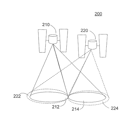
redundancy
while improving the quality of the communication links supported by the system
200.
The system 200 includes a first communication satellite having first and
second beams
CA 02560549 2006-09-18
WO 2005/091528 PCT/US2005/008741
7
that respectively illuminate first and second regions 212 and 214. The system
200 also
includes a second communication satellite 220 having first and second beams
that
respectively illuminate first and second regions 222 and 224. In one
embodiment, the
first and second regions 212 and 214 supported by the first satellite 210
substantially
overlap the first and second regions 222 and 224 supported by the second
satellite 220.
As noted earlier, any of the beams may include one or more beams configured to
illuminate the region.
[0028] Unlike the prior art system shown in Figure lA, the communication
system
200 of Figure 1B uses both satellites 210 and 220 to support communication
links. The
first communication satellite 210 can be configured to receive reverse link
signals from
its supported regions 212 and 214 and relay them to one or more ground
stations (not
shown). Similarly, the second communication satellite 220 can be configured to
receive
reverse link signals from its supported regions 222 and 224 and relay them to
one or
more ground stations (not shown), which may in some cases include one or more
ground stations communicating with the first communication satellite 210.
[0029] In the forward linlc direction, each of the communication satellites
210 and 220
is designated as a primary satellite for one or more of the regions. In one
embodiment,
the first communication satellite 210 can be designated the primary satellite
for the first
region 212 and can be designated a secondary satellite for the second region
214.
Similarly, the second communication satellite 220 can be designated the
primary
satellite for the second region 224 and a secondary satellite for the first
region 222.
Therefore, the second communication satellite 220 serves as the secondary
satellite for
the region 212 where the first communication satellite 210 is the primary
satellite.
Similarly, the first communication satellite 210 serves as the secondary
satellite for the
region 224 where the second communication satellite 220 is the primary
satellite.
[0030] The primary satellite transmits strong overhead signals to the region
for which
it is designated the primary satellite and transmits a weaker overhead signal
to the
region for which the satellite is designated the secondary satellite. The
overhead signals
can include, for example, pilot, paging, and sync channels.
[0031] Under typical operating conditions, the primary satellite transmits the
forward
link signal to the region for which it is the primary satellite and does not
transmit traffic
CA 02560549 2006-09-18
WO 2005/091528 PCT/US2005/008741
8
signals destined for the regions for which the satellite is not the primary
satellite. Thus,
for a given region, a primary satellite transmits strong overhead signals and
transmits
traffic channels to receivers within the region. A secondary satellite
transmits weaker
overhead signals to the region, but ordinarily does not transmit traffic
channels to the
region.
[0032] However, if a receiver in a region experiences a loss of signal
quality, for
example, due to a loss of signal strength from the primary satellite, the
system 200 can
switch or otherwise transfer the communication link to the secondary
satellite.
Therefore, when a communication link from a primary satellite is degraded, the
communication link can be switched to or otherwise transferred to a secondary
satellite
providing coverage to the region. The communication link can be transferred
back to
the primary satellite when the communication link from the primary satellite
recovers
from the degraded condition.
[0033] In one embodiment, the first communication satellite 210 can have two
beams
that illuminate the continental United States. A first region 212 can be, for
example, the
western continental United States and a second region 214 can be, for example,
the
eastern continental United States. The second communication satellite 220 can
be
configured to have two beams that illuminate regions that substantially
overlap the
regions of the first communication satellite 210. Thus, the first region 222
of the second
communication satellite 220 can cover the western continental United States
and can
substantially overlap the first region 212 of the first communication
satellite 210. The
second region 224 of the second communication satellite 220 can cover the
eastern
United States and can substantially overlap the second region 214 of the first
communication satellite.
[0034] The first communication satellite 210 can be configured to be the
primary
satellite for the eastern United States and can be the secondary satellite for
the western
United States. The second communication satellite 220 can be configured to be
the
primacy satellite for the western United States and can be the secondary
satellite for the
eastern United States.
[0035] In the reverse link direction, both the first and second communication
satellites
210 and 220 can receive transmissions from both of the regions and can relay
the signals
CA 02560549 2006-09-18
WO 2005/091528 PCT/US2005/008741
9
to the appropriate ground stations. In the forward link direction, the first
communication satellite 210 transmits relatively strong overhead signals to
its second
region 214. The first communication satellite 210 also transmits the traffic
channels to
its second region 214. The second communication satellite 220 transmits
relatively
weak overhead signals to its second region 224 and does not transmit traffic
channels to
its second region 224 unless the forward link signal from the first
communication
satellite 210 is degraded.
[0036] In this embodiment, forward link operation in the western United States
is
similar except the second communication satellite 220 broadcasts the stronger
overhead
signals and takes primary responsibility for the traffic channels. The first
communication satellite 210 broadcasts relatively weaker overhead signals and
transmits to the region those traffic channels switched to it due to degraded
conditions
on the second communication satellite 220.
[0037] Using the above described embodiment, each of the satellites can be
configured to operate as in-orbit spares for the other satellite, while
providing
communication benefits not available in a dormant spare satellite system. As
both
satellites approach one-half loading, a third satellite can be placed into
orbit as a
dormant spare, or may be integrated into the system 200 using additional beam
assignments. The additional satellite can be used to ensure that full traffic
can continue
if one satellite fails. This is similar to the conventional approach having a
single
satellite and an inactive in-orbit spare, where at least one additional
satellite is needed
when the communication load approaches the limit of the single active
satellite.
[0038] Although the embodiment shown in Figure 1B shows two satellites 210 and
220 with each satellite having two beams, other embodiments can use more than
two
satellites and each satellite can have more than two beams. For example, a
system may
include three satellites and each of the satellites can have a plurality of
beams. Each
satellite can be configured to be a primary satellite for one or more of the
regions
supported by the plurality of beams. Typically, each region has one primary
satellite.
Each satellite can also be configured to be a secondary satellite for one or
more regions
suppouted by the plurality of beams for which the satellite is not configured
to be a
primary satellite. In some embodiments, more than one satellite can be
designated as
secondary satellites for a particular region. In other embodiments, each
region has one
CA 02560549 2006-09-18
WO 2005/091528 PCT/US2005/008741
of the multiple satellites configured as a secondary satellite. In still other
embodiments,
the satellites can be ranked in a hierarchy, such that a region is supported
by multiple
satellites in the order of the hierarchy.
[0039] Figure 2 is a more detailed functional block diagram of a communication
system 200 showing multiple satellites configured to provide redundant
communication
links to a region. The system 200 shown in Figure 2 can be, for example, the
same as
the system shown in Figure 1B. Although multiple regions may be supported by
the
system, a single region is shown for the purposes of clarity.
[0040] The communication system 200 of Figure 2 can be, for example, a
satellite
telephone system, a satellite data communication system, such as a computer
network
having satellite links within the network, and the lilce, or some other type
of
communication system. The communication system 200 can include a first
communication satellite 210 operating as a primary satellite and a second
communication satellite 220 operating as a secondary satellite. In this
embodiment, the
term primary refers to the satellite's designation as the primary satellite
for the region
shown in Figure 2. Similarly, the term secondary refers to the satellite's
designation as
the secondary satellite for the region shown in Figure 2. A satellite that is
the primary
satellite for one region may be a secondary satellite for another region.
Similarly, a
satellite that is the secondary satellite for a region may be a primary
satellite for another
region. The satellites 210 and 220 can be, for example, geostationary
satellites, medium
earth orbit satellites, low earth orbit satellites, or satellites in some
other orbit.
[0041] The system 200 also includes a ground station 240 that may be, for
example, a
base station, gateway, and the like, or some other system apparatus for
interfacing with
a ground communication system. The system 200 may include multiple ground
stations
240. Only one ground station 240 is shown for the sake of brevity. The ground
station
240 can provide the interface between the satellites 210 and 220 and the
remainder of
the communication system (not shown). For example, where the communication
system 200 is a telephone system, the ground station 240 can be a satellite
gateway that
interfaces to a mobile controller and Public Switched Telephone Network
(PSTN). In
other embodiments, the ground station 240 can be an Internet gateway that
interfaces
the satellite communications to a network, such as the Internet.
CA 02560549 2006-09-18
WO 2005/091528 PCT/US2005/008741
11
[0042] The system 200 can include one or more mobile stations 250, although
only
one is shown in Figure 2. The mobile station 250 can be, for example, a
portable
telephone, portable communication device such as a notebook computer or
personal
digital assistant, a fixed wireless device, and the like, or some other
communication
device.
[0043] In the embodiment shown in Figure 2, communications between the ground
station 240 and the mobile station 250 may occur over one or more satellite
links. In the
reverse link direction, each communication satellite 210 and 220 receives the
signal
from all beams and relays these signals to the ground station 240 where they
can be
combined. The mobile station 250 typically transmits the reverse link signals
using a
broad beam antenna that permits the signal to be transmitted or received
simultaneously
from multiple satellites.
[0044] The first communication satellite 210 relays a first reverse link
signal 246a
from the mobile station 250 as a first satellite reverse link signal 248a to
the ground
station 240. The second communication satellite 220 relays a second reverse
link signal
246b from the mobile station 250 as a second satellite reverse link signal
248b to the
ground station 240. The ground station 240 can then combine the satellite
reverse link
signals 248a and 248b to improve the signal to noise ratio (SNR) of the
reverse link
signal.
[0045] Diversity combining in the reverse direction essentially provides a
"free"
benefit as the signal from the mobile station 250 reaches the satellites 210
and 220
regardless of whether the satellite relays the signal to the ground station
250. The
satellites 210 and 220 use a negligible amount of power to relay the reverse
link signals
248a-b to the ground station 240. Combining the signals at the ground station
240 can
provide up to 3 dB more SNR, assuming equal strength signals reach the
satellites 210
and 220. The improvement can be 3 dB for signaling protocols such as Code
Division
Multiple Access (CDMA) 2000 where the ground station 240 or some subsequent
signal
processing stage can perform coherent combining. The improvement can be
approximately 1.8 dB gain if non-coherent combining is used.
[0046] In other embodiments, the satellites 210 and 220 and the ground station
240
can be configured to receive multiple polarizations, for example Left Hand
Circular
CA 02560549 2006-09-18
WO 2005/091528 PCT/US2005/008741
12
(LHC) and Right Hand Circular ( RHC) or vertical and horizontal, for diversity
combining at the ground station 240. The satellites 210 and 220 may be
configured to
receive and relay multiple signal polarities in order to extract every bit of
power out of
the signal.
[0047] Combining the reverse link signals 248a-b from both satellites 210 and
220
costs the system 200 almost nothing in power. However, signal combining in the
reverse link direction provides up to a 3dB gain in SNR if neither signal is
blocked.
Satellite diversity is achieved such that if one reverse linlc signal path is
blocked the
communication link can continue over the redundant link. In some embodiments,
the
system 200 may direct the mobile station 250 using a power control technique
to
increase the mobile station 250 transmit power in order to restore the SNR if
one link is
lost.
[0048] In one embodiment, the system 200 can operate the forward link in a
manner
similar to the reverse link. The ground station 240 can transmit forward link
signals
242a-b to both satellites 210 and 220 and the satellites 210 and 220 can relay
the
forward link signals 244a-b to the mobile station 250. The mobile station 250
can then
individually track the forward link signals 244a-b and combine them at the
mobile
station 250.
[0049] However, in the forward direction there is a tradeoff between power and
diversity. It may be advantageous for the system 200 to implement diversity
for the
condition where one of the paths is suddenly blocked. The forward link
embodiment
that mirrors the reverse linlc signaling can accomplish diversity by
configuring both
satellites 210 and 220 to illuminate the mobile station 250. However, such an
embodiment requires increased satellite power.
[0050] Each satellite 210 and 220 typically cannot be configured to supply
only one-
half the power radiated by a single satellite configuration. Providing one-
half the power
in each satellite 210 and 220 would result in the same total power over both
satellites
compared to a single satellite transmitting the signal. However, in multiple
satellite
configurations, each satellite has to transmit considerable more than one-half
the power
of an equivalent signal satellite system.
CA 02560549 2006-09-18
WO 2005/091528 PCT/US2005/008741
13
[0051] Each satellite 210 and 220 typically needs to be configured to transmit
greater
than one-half the power of an equivalent single satellite system because the
signal from
each satellite, for example 210, represents an interference signal for the
signal
transmitted by the other satellite, for example 220. For example, a mobile
station 250
receiving both signals in a CDMA based system, has separate fingers of a RAKE
receiver receiving one of the reverse link signals. Each finger of the RAKE
receiver
sees the other signal as interference. Thus, the diversity gain of multiple
simultaneous
forward link satellite signals comes at the cost of more satellite power.
[0052] Another embodiment of the system 200 of Figure 2 capitalizes on the
benefits
of diversity gain yet uses very little more power in the satellites 210 and
220. In the
embodiment, one of the satellites, for example 210, takes primary
responsibility for
providing service to a given region on the ground, which may represent a cell
of a
cellular communication system. The two satellites 210 and 220 can divide the
communication responsibilities with each talung primary responsibility for
half the
cells.
[0053] The primary satellite, here the first communication satellite 210,
communicates the overhead signals to the region. The overhead signals can
include, for
example, pilot, paging, and sync (PPS) channels. The sync channel can include,
for
example, a timing reference signal, and a paging channel can include, for
example,
control signaling messages directed to the mobile station 250. The satellite
configured
as the primary satellite, for example the first communication satellite 210,
can be
configured to transmit the overhead signals with much greater power than is
typically
required to complete the communication link to the mobile station 250 in a
clear or
unblocked condition. For example, the first communication satellite 210 can be
configured to transmit the PPS signals as relatively strong signals. To ensure
a robust
link, the first communication satellite 210 can be configured to transmit
relatively
strong PPS signals that are elevated approximately 5-IOdB over the minimum
power
level required to complete a communication link with the mobile station 250.
Of
course, the first communication satellite 210 is not limited to transmitting
at an elevated
level that is 5-lOdB above the minimum power level, but may be configured to
transmit
at a level that is greater than the minimum power level by a predetermined
link margin.
The predetermined link margin may be a static level or may vary. For example,
the
CA 02560549 2006-09-18
WO 2005/091528 PCT/US2005/008741
14
value of the link margin may vary over time. The link margin may be set to,
for
example, 5dB, 6dB, 7 dB, 8dB, 9dB, or 10 dB. The primary satellite can be
configured
to transmit the signals at a relatively strong level that is above the minimum
link
requirement such that there is a high likelihood the mobile station 250 can
receive the
signals through obstructions.
[0054] The secondary satellite, here the second communication satellite 220,
is also
configured to transmit the overhead pilot, paging and sync (PPS) signals to
the region.
However, the overhead PPS signals on the secondary satellite need not be
transmitted at
an elevated level. In one embodiment, the overhead signals from the second
communication satellite 220 can be transmitted at as low as one decibel or two
decibel
above the minimum link requirement in order to allow for Rician fading. In
another
embodiment, the second communication satellite 220 can be configured to
transmit the
PPS signals at a level sufficient to provide a 90% reliability. The two
satellites 210 and
220 covering the region can be configured, for example, to use different
spreading
codes.
[0055] If the mobile station 250 is able to receive signals from both
satellites 210 and
220, the communication link such as a call is set up on the primary satellite
210 using its
paging channel. The forward link traffic channel is set up using the primary
satellite,
here the first communication satellite 210. If none of the communication links
from the
primary satellite to the associated mobile station 250 is blocked, then the
power on the
secondary satellite remains the relatively small PPS power. Therefore the
signals from
the secondary satellite, here the second communication satellite 220,
contributes little
interference at the mobile station 250 to the forward link signal from the
first
communication satellite 210. However, if the mobile station 250 communicating
on the
traffic channel over the first communication satellite 210 experiences
sufficiently high
blockage, the communication link can be transferred to the secondary
satellite.
[0056] Figure 3 is a functional block diagram of an embodiment of the
communication system 200 and can represent the communication system 200 of
Figure
2. As shown in previous functional block diagram, the communication system 200
includes a ground station 240 in communication with a first communication
satellite 210
and a second communication satellite 220. The two satellites 210 and 220 are
also in
communication with a mobile station 250. The number of ground stations 240,
CA 02560549 2006-09-18
WO 2005/091528 PCT/US2005/008741
satellites 210 and 220, and mobile stations 250 are not limited by the numbers
shown in
the functional diagram. A minimal number of system 200 elements are shown for
ease
of discussion.
[0057] The ground station 240 can include a gateway transceiver 310 configured
to
communicate over the forward and reverse links with the satellites 210 and
220. The
ground station 240 can also include a quality of service (QoS) module 312
configured to
determine a quality of service indication or value corresponding to the
communication
links to the mobile station 250. For example, the QoS module 312 can be
configured to
determine a signal metric from a signal transmitted by the mobile station 250
that is
indicative of the signal quality received from the satellites 210 and 220. The
QoS
module 312 can communicate the signal metric or a signal determined from the
signal
metric to a link control module 314.
[0058] The link control module 314 can be configured to determine, based in
part on
the signal metric, which satellite 210 or 220 is to be configured to transmit
the forward
link signal to the mobile station 250. The link control module 314 can be
configured to
control the gateway transceiver 310 to transmit the forward link signal to the
mobile
station 250 using the primary or secondary satellite. In one embodiment, the
link
control module 314 can be configured to set a flag or indicator that informs
the gateway
transceiver 310 of the satellite to use. In another embodiment, the link
control module
314 can be configured to provide an address to the gateway transceiver 310
that directs
the forward link communication to the desired satellite. The gateway
transceiver 310
may transmit the forward link signal to multiple satellites 210 and 220, but
the signal
may be relayed by the desired satellite based on contents of the transmitted
signal. In
still other embodiments, the link control module 314 may communicate the
desired
satellite to the gateway transceiver 310 in some other manner.
[0059] Each of the satellites 210 and 220 can be, but are not required to be,
configured similarly. The first communication satellite 210 can include a
forward link
transceiver 320 configured to receive the forward linlc signals from the
ground station
240 and relay them to the desired mobile station 250 in the desired region.
The first
communication satellite 210 can also include a reverse link transceiver 322
configured
to receive reverse link communications transmitted by the mobile station 250
in any
supported region and relay them to the ground station 240. The second
communication
CA 02560549 2006-09-18
WO 2005/091528 PCT/US2005/008741
16
satellite 220 similarly can include a forward link transceiver 330 and a
reverse link
transceiver 332.
[0060] The mobile station 250 can include a mobile transceiver 340 that is
configured
to receive the forward link signals transmitted by the satellites 210 and 220.
The mobile
transceiver 340 can be configured to convert the received forward link signals
to
baseband signals that are processed by a baseband processor 350. The mobile
transceiver 340 can also be configured to receive baseband signals from the
baseband
processor and convert the baseband signals to reverse link signals that are
transmitted to
the satellites 210 and 220.
[0061] The baseband processor 350 can include one or more modules configured
to
determine the quality of the forward link signals received from the satellites
210 and
220. In one embodiment, the baseband processor 350 can include a first
received signal
strength indicator (RSSI) module 352 configured to determine a signal strength
of the
forward link pilot signal from the first communication satellite 210. The
baseband
processor 350 can also include a second RSSI module 354 configured to
determine a
signal strength of the forward link pilot signal from the second communication
satellite
220. The baseband processor 350 can also include a processor 360 and memory
362.
The processor 360 in conjunction with one or more processor readable
instructions
stored in memory 362 can perform some or all of the functions of the RSSI
modules 352
and 354.
[0062] The mobile station 250, using the RSSI modules 352 and 354, monitors
the
received pilot signals and determines a signal quality such as a RSSI. The
mobile
station 250 can report the RSSI values back to the ground station 240. In one
embodiment, the mobile station 250 reports the RSSI values back to the ground
station
240 using one or more of the overhead channels. For example, the mobile
station 250
can be configured to transmit the RSSI values on a paging channel that is
transmitted
from the mobile station 250 over the satellites 210 and 220 to the ground
station 240.
The ground station 240 can compare the received RSSI values against
predetermined
thresholds and determine if the forward link communication should be
transferred to the
secondary satellite. Because the satellites 210 and 220 can be configured to
transmit
different pilot power levels to the same region, the predetermined thresholds
may be
different fro the first satellite 210 and the second satellite 220.
CA 02560549 2006-09-18
WO 2005/091528 PCT/US2005/008741
17
[0063] If the pilot strength report indicates that the primary path has slight
attenuation, the communication can still continue on the primary satellite.
The ground
station 250 can be configured to keep the secondary satellite largely free of
traffic in
part to reduce its interference contribution to signals from the primary
satellite. At the
point at which the RSSI value reported for the primary satellite no longer
exceeds the
predetermined threshold, the system 200 may determine that the blockage or
degradation of the primary path is large enough such that the power to
overcome the
degradation becomes excessive. Once this threshold is reached, the
communication can
be transferred to the secondary satellite that is used to provide an
alternative signal path.
[0064] Control signaling to transfer the communication link can take place
from the
traffic channel on the primary link or, if degradation is particularly high,
using a
secondary paging channel. In a system 200 embodiment where the satellites 210
and
220 are geostationary satellites, the transition may not be seamless. In a
geostationary
system there may be a 1/2 second round trip communication delay. Therefore, it
may
take 1-2 seconds to transfer the communication between satellites. It is not
necessary to
elevate the power of the overhead channels on the secondary satellite because
the
secondary satellite is typically used for clear communication paths. If the
primary path
is blocked or otherwise heavily attenuated and the secondary path is blocked
or lightly
attenuated the communication link may drop.
[0065] Because the secondary satellite channel has a relatively weak overhead
signaling and a few light traffic channels there is hardly any interference
effect felt on
receivers of signals from the primary satellite. This gives the advantage of
satellite
diversity without paying the high power needed of a system using simultaneous
transmission by multiple satellites.
[0066] Figure 4 is a flowchart of an embodiment of a method 400 of providing
satellite diversity. The method 400 can be implemented, for example, in the
system 200
of Figure 3. The method 400 begins at block 410 after the initial
communication link is
set up on a traffic channel of the primary satellite.
[0067] At block 410 the system transmits the signal to the mobile station over
the
traffic channel of the primary satellite. The system proceeds to block 420 and
monitors
for signal fade. As noted above, the mobile station can be configured to
monitor the
CA 02560549 2006-09-18
WO 2005/091528 PCT/US2005/008741
18
signal quality of the forward link paths from the multiple satellites. In one
embodiment,
the mobile station can be configured to determine the RSSI values of the
primary and
secondary pilot signals. The mobile station can then be configured to report
the values
back to the ground station in a reverse link overhead message, such as in a
power
control message reported on a paging channel.
[0068] The system proceeds to decision block 430 to determine if the fade
exceeds a
predetermined threshold. In one embodiment, a QoS module in the ground station
compares the reported RSSI values to predetermined thresholds. The RSSI
corresponding to the primary satellite can be compared against, a first
threshold value
and the RSSI value from the secondary satellite can be compared against a
second
predetermined threshold. The system may determine that the primary satellite
path is
fading or otherwise attenuated based in part on the comparison of the RSSI of
the
primary satellite to the corresponding threshold. If the RSSI does not exceed
the
threshold, the system may determine a fade has occurred. Provided the RSSI of
the
secondary satellite is above its threshold the communication link can
successfully be
transferred to the secondary satellite.
[0069] If the system determines that a fade has not occurred, the system
returns to
block 410 and continues to support the communication link using the primary
satellite.
However, if in decision block 430 the system determines that the fade is
greater than an
acceptable threshold the system proceeds to block 440.
[0070] In block 440 the system transfers the communication link to the
secondary
satellite. The mobile station can be informed of the transfer using, for
example, control
signaling that is included on the traffic channel of the primary satellite
prior to the
transfer or on a paging channel of the secondary satellite. The system begins
transmitting the traffic channel signal using the secondary communication
satellite. The
system proceeds to block 450 and ceases transmitting the traffic channel on
the primary
satellite.
[0071] Once the system has transferred the communication link to the secondary
path,
the system may allow the communication to continue over the secondary link
until the
link is terminated, for example, by a user of the mobile station. However, in
order to
maintain minimal traffic loading on the secondary link, the system may be
configured to
CA 02560549 2006-09-18
WO 2005/091528 PCT/US2005/008741
19
transfer the communication link back to the primary satellite when the primary
path
recovers from a degraded condition.
[0072] The system proceeds to decision block 460 to determine if the fade
condition
experienced by the primary path has diminished. In decision block 460, the
system can
compare the RSSI values reported by the mobile stations against the
predetermined
thresholds. If the system determines that the RSSI value of the primary path
does not
exceed the predetermined threshold, the system may return to block 440 and
continue to
support the communication link over the secondary satellite.
[0073] Returning to decision block 460, if the system determines that the RSSI
value
of the primary path has returned to an acceptable value, such as when the RSSI
value
exceeds the predetermined threshold, the system may determine that the fade
condition
is over. The system can proceed from decision block 460 to block 470. The
system
proceeds to transfer the communication link back to the primary satellite. As
before, the
system can use control signaling to inform the mobile station of the change in
the
communication link. At block 470 the system sets up the primary channel to
carry the
forward link signal. After setting up the primary channel, the system proceeds
to block
472 and transmits the signal on the primary satellite beam. The system then
proceeds to
block 474 where the system ceases transmitting on the secondary satellite. The
system
then returns to block 420 and continues to monitor fox a signal fade. The
system can
continue to perform the method 400 until the communication link is terminated,
for
example, by the user of the mobile station or by a user or system
communicating with
the mobile station.
[0074] Figure 5 is a flowchart of a method 500 of providing satellite
diversity. The
method 500 can be performed, for example, by the ground station of the
communication
system of Figure 3.
[0075] The method 500 begins at bloclc 510 where the ground station provides
the
forward link signal to the primary satellite, which may be a primary satellite
repeater.
The ground station proceeds to block 520 and receives the pilot RSSI values
reported by
the mobile station.
[0076] The ground station proceeds to block 522 and compares the received RSSI
values to the predetermined thresholds. At decision block 530, the ground
station
CA 02560549 2006-09-18
WO 2005/091528 PCT/US2005/008741
determines if the primary RSSI is greater than the threshold. If it is, the
ground station
returns to block 510 and continues to transmit the signal to the primary
satellite.
[0077] Returning to decision block 530, if the RSSI is not greater than the
threshold,
the ground station proceeds to block 540 and stops transmitting to the primary
satellite.
The ground station proceeds to block 542 and begins transmitting to the
secondary
satellite. In other embodiments, the ground station may make the communication
link
with the secondary satellite before brealung the link with the primary
satellite.
[0078] The ground station then proceeds to block 550 and receives the pilot
RSSI
values from the mobile station. At block 552 the ground station compares the
received
RSSI values to the thresholds. The ground station proceeds to bloclc 560 to
determine if
the primary communication path can sustain the communication link. If not, the
ground
station proceeds back to bloclc 542 and continues to transmit to the secondary
satellite.
[0079] Returning to decision block 560, if the ground station determines that
the RSSI
value exceeds the threshold the ground station proceeds to bloclc 570 and sets
up the
primary channel for transmission over the primary satellite. The ground
station then
proceeds to block 572 and provides the signal to the primary satellite for
transmission.
The ground station proceeds to block 574 and terminates transmitting to the
secondary
satellite. The ground station proceeds back to block 520 and receives the
pilot RSSI
that is an indicator of the quality of the communication link. The ground
station
continues to perform the method 500 until the communication linlc drops or is
other
wise terminated.
[0080] A system and method of satellite diversity is disclosed. The disclosed
systems
and methods allow for diversity in a satellite communication system by
incorporating
system functionality in multiple satellites. In one embodiment, two satellites
are used
and each satellite functions as an in-orbit spare for the other satellite.
Each satellite
supports two beams and the beams of the satellites illuminate regions that
substantially
overlap. Each satellite is a primary satellite for one of the beams and is the
secondary
satellite for the other beam. The primary beam of the first satellite
corresponds to a
region which corresponds with the secondary beam of the second satellite.
[0081] The system is able to achieve reliable communications by setting up
communications on the primary satellite and transferring communications to the
CA 02560549 2006-09-18
WO 2005/091528 PCT/US2005/008741
21
secondary satellite when the communication path over the primary satellite is
degraded.
The secondary satellite is minimally loaded because it carries relatively
weaker
overhead signals and carries traffic channels that correspond to degraded
primary
communication links. Thus, the secondary satellite contributes a minimal
interference
signal to the primary communication link.
[0082] The various illustrative logical blocks, modules, circuits, and
algorithm steps
described in connection with the embodiments disclosed herein may be
implemented as
electronic hardware, computer software, or combinations of both. To clearly
illustrate
this interchangeability of hardware and software, various illustrative
components,
blocks, modules, circuits, and steps have been described above generally in
terms of
their functionality. Whether such functionality is implemented as hardware or
software
depends upon the particular application and design constraints imposed on the
overall
system. Persons of ordinary skill in the art may implement the described
functionality
in varying ways for each particular application, but such implementation
decisions
should not be interpreted as causing a departure from the scope of the
disclosure.
[0083] The various illustrative logical blocks, modules, and circuits
described in
connection with the embodiments disclosed herein may be implemented or
performed
with a general purpose processor, a digital signal processor (DSP), a Reduced
Instruction Set Computer (RISC) processor, an application specific integrated
circuit
(ASIC), a field programmable gate array (FPGA) or other programmable logic
device,
discrete gate or transistor logic, discrete hardware components, or any
combination
thereof designed to perform the functions described herein. A general purpose
processor may be a microprocessor, but in the alternative, the processor may
be any
processor, controller, microcontroller, or state machine. A processor may also
be
implemented as a combination of computing devices, for example, a combination
of a
DSP and a microprocessor, a plurality of microprocessors, one or more
microprocessors
in conjunction with a DSP core, or any other such configuration.
[0084] The steps of a method, process, or algorithm described in connection
with the
embodiments disclosed herein may be embodied directly in hardware, in a
software
module executed by a processor, or in a combination of the two. A software
module
may reside in RAM memory, flash memory, non-volatile memory, ROM memory,
EPROM memory, EEPROM memory, registers, hard disk, a removable disk, a CD-
CA 02560549 2006-09-18
WO 2005/091528 PCT/US2005/008741
22
ROM, or any other form of storage medium known in the art. An exemplary
storage
medium is coupled to the processor such the processor can read information
from, and
write information to, the storage medium. In the alternative, the storage
medium may be
integral to the processor. Further, the various methods may be performed in
the order
shown in the embodiments or may be performed using a modified order of steps.
Additionally, one or more process or method steps may be omitted or one or
more
process or method steps may be added to the methods and processes. An
additional
step, block, or action may be added in the beginning, end, or intervening
existing
elements of the methods and processes.
[0085] The above description of the disclosed embodiments is provided to
enable any
person of ordinary skill in the art to make or use the disclosure. Various
modifications
to these embodiments will be readily apparent to those of ordinary skill in
the art, and
the generic principles defined herein may be applied to other embodiments
without
departing from the spirit or scope of the disclosure. Thus, the disclosure is
not intended
to be limited to the embodiments shown herein but is to be accorded the widest
scope
consistent with the principles and novel features disclosed herein.