Language selection

Search

Patent 2560578 Summary

Third-party information liability

Some of the information on this Web page has been provided by external sources. The Government of Canada is not responsible for the accuracy, reliability or currency of the information supplied by external sources. Users wishing to rely upon this information should consult directly with the source of the information. Content provided by external sources is not subject to official languages, privacy and accessibility requirements.

Claims and Abstract availability

Any discrepancies in the text and image of the Claims and Abstract are due to differing posting times. Text of the Claims and Abstract are posted:

  • At the time the application is open to public inspection;
  • At the time of issue of the patent (grant).
(12) Patent Application: (11) CA 2560578
(54) English Title: PORTABLE HITCH MOUNTED CARGO CARRIER
(54) French Title: TRANSPORTEUR DE MARCHANDISES PORTATIF MONTE SUR ATTELAGE
Status: Dead
Bibliographic Data
(51) International Patent Classification (IPC):
  • B60R 9/06 (2006.01)
  • B60S 9/14 (2006.01)
  • B62B 3/02 (2006.01)
  • B62D 63/06 (2006.01)
  • B65D 90/18 (2006.01)
(72) Inventors :
  • MYREX, LEE (United States of America)
(73) Owners :
  • MYREX, LEE (United States of America)
(71) Applicants :
  • MYREX, LEE (United States of America)
(74) Agent: RIDOUT & MAYBEE LLP
(74) Associate agent:
(45) Issued:
(22) Filed Date: 2006-09-21
(41) Open to Public Inspection: 2007-04-14
Availability of licence: N/A
(25) Language of filing: English

Patent Cooperation Treaty (PCT): No

(30) Application Priority Data:
Application No. Country/Territory Date
11/250,898 United States of America 2005-10-14

Abstracts

English Abstract


A cargo carrier having a hitch sleeve on its bottom and legs with wheels on
its
sides. A hitch shaft is inserted into a trailer hitch on a vehicle and the
hitch sleeve fits
over the hitch shaft. The legs have an internal screw type jack mechanism to
raise and
lower the cargo carrier to place the hitch sleeve over the hitch shaft, and to
raise the legs
so that the vehicle can transport the cargo carrier on the hitch shaft without
having to
remove the legs. The wheels allow the cargo carrier to be portable when not
connected to
the vehicle and allow the hitch sleeve to be aligned with the hitch shaft to
facilitate
insertion of bolts through the hitch sleeve and hitch shaft, thereby fastening
the cargo
carrier to the hitch shaft. The legs can be rotatably mounted to the cargo
carrier to
provide additional clearance of the legs above the ground by rotating them,
once the
cargo carrier hitch sleeve is connected to the hitch shaft inserted in the
vehicle trailer
hitch.


Claims

Note: Claims are shown in the official language in which they were submitted.


Claims
I claim:

1. A cargo carrier, comprising:
a) a top having a lid, sides having legs, and a bottom having a hitch
sleeve;
b) a hitch shaft reversibly connecting to said hitch sleeve and to a
trailer hitch on a vehicle;
c) said legs having an internal jack mechanism to raise and lower said
cargo carrier to place said hitch sleeve over said hitch shaft, and to
raise said legs so that said vehicle can transport said cargo Garner
on said hitch shaft, and
d) said legs having wheels so that said hitch sleeve is alignable with
said hitch shaft and so that said cargo carrier is portable when not
connected to said vehicle.

2. The cargo carrier of claim 1 wherein said legs have an upper portion and
lower portion, said jack mechanism lengthening said leg by extending said
lower
portion of said leg out of said upper portion of said leg, and shortening said
leg by
withdrawing said lower portion of said leg into said upper portion of said
leg.

3. The cargo carrier of claim 1 wherein said legs are attached rotatably to
said cargo carrier.

4. The cargo carrier of claim 2 wherein said jack mechanism consists of a
worm gear arrangement and a screw shaft inside said upper portion of said leg
which move said lower portion of said leg into and out of said upper portion
of
said leg as said jack mechanism is activated.

7


5. The cargo carrier of claim 3 wherein said legs have a clamp frame which
fits rotatably on a sleeve of a sleeve base, said sleeve base being fixed to
said
cargo carrier.

6. The cargo carrier of claim 5 wherein said clamp frame has locking pins
and said sleeve base has locking pin holes so that said clamp frame and said
leg
are held in a fixed position by said locking pins being reversibly inserted
into said
locking pin holes.

7. The cargo carrier of claim 1 wherein said legs are inside said cargo
carrier,
said legs having an upper portion and a lower portion whereby said lower
portion
of said leg is able to pass through said bottom of said cargo carrier.

8. The cargo carrier of claim 7 wherein said jack mechanism lengthens said
leg by extending said lower portion of said leg out of said upper portion of
said
leg, and shortens said leg by withdrawing said lower portion of said leg into
said
upper portion of said leg.

9. The cargo carrier of claim 8 wherein said jack mechanism consists of a
worm gear arrangement and a screw shaft inside said upper portion of said leg,
whereby said worm gear arrangement and said screw shaft move said lower
portion of said leg into and out of said upper portion of said leg as said
jack
mechanism is activated.

10. A cargo carrier, comprising:
a) a top having a lid, sides having legs, and a bottom having a hitch
sleeve;
b) a hitch shaft reversibly connecting to said hitch sleeve and to a
trailer hitch on a vehicle;
c) said legs having an internal jack mechanism to raise and lower said
cargo Garner to place said hitch sleeve over said hitch shaft, and to

8


raise said legs so that said vehicle can transport said cargo carrier
on said hitch shaft;
d) said legs having wheels so that said hitch sleeve is alignable with
said hitch shaft and so that said cargo carrier is portable when not
connected to said vehicle; and
e) said legs having an upper portion and lower portion, said jack
mechanism lengthening said leg by extending said lower portion of
said leg out of said upper portion of said leg, and shortening said
leg by withdrawing said lower portion of said leg into said upper
portion of said leg.

11. The cargo carrier of claim 10 wherein said legs are attached rotatably to
said cargo carrier.

12. The cargo carrier of claim 10 wherein said jack mechanism consists of a
worm gear arrangement and a screw shaft inside said upper portion of said leg
which move said lower portion of said leg into and out of said upper portion
of
said leg as said jack mechanism is activated.

13. The cargo carrier of claim 11 wherein said legs have a clamp frame which
fits rotatably on a sleeve of a sleeve base, said sleeve base being fixed to
said
cargo carrier.

14. The cargo carrier of claim 13 wherein said clamp frame has locking pins
and said sleeve base has locking pin holes so that said clamp frame and said
leg
are held in a fixed position by said locking pins being reversibly inserted
into said
locking pin holes.

15. The cargo carrier of claim 10 wherein said legs are inside said cargo
carrier, whereby said lower portion of said leg is able to pass through said
bottom
of said cargo carrier.

9


16 The cargo carrier of claim 15 wherein said jack mechanism consists of a
worm gear arrangement and a screw shaft inside said upper portion of said leg,
whereby said worm gear arrangement and said screw shaft move said lower
portion of said leg into and out of said upper portion of said leg as said
jack
mechanism is activated.

17. A cargo carrier, comprising:
a) a top having a lid, sides having legs, and a bottom having a hitch
sleeve;
b) a hitch shaft reversibly connecting to said hitch sleeve and to a
trailer hitch on a vehicle;
c) said legs having an internal jack mechanism to raise and lower said
cargo carrier to place said hitch sleeve over said hitch shaft, and to
raise said legs so that said vehicle can transport said cargo carrier
on said hitch shaft;
d) said legs having wheels so that said hitch sleeve is alignable with
said hitch shaft and so that said cargo carrier is portable when not
connected to said vehicle; and
e) said legs attached rotatably to said cargo carrier, wherein said legs
have a clamp frame which fits rotatably on a sleeve of a sleeve
base, said sleeve base being fixed to said cargo carrier.

18. The cargo carrier of claim 17 wherein said legs have an upper portion and
lower portion, said jack mechanism lengthening said leg by extending said
lower
portion of said leg out of said upper portion of said leg, and shortening said
leg by
withdrawing said lower portion of said leg into said upper portion of said
leg.

19. The cargo carrier of claim 18 wherein said jack mechanism consists of a
worm gear arrangement and a screw shaft inside said upper portion of said leg
which move said lower portion of said leg into and out of said upper portion
of
said leg as said jack mechanism is activated.


20. The cargo carrier of claim 17 wherein said clamp frame has locking pins
and said sleeve base has locking pin holes so that said clamp frame and said
leg
are held in a fixed position by said locking pins being reversibly inserted
into said
locking pin holes.

21. The cargo carrier of claim 17 wherein said legs are inside said cargo
carrier, said legs having an upper portion and a lower portion whereby said
lower
portion of said leg is able to pass through said bottom of said cargo carrier.

22. The cargo carrier of claim 21 wherein said jack mechanism lengthens said
leg by extending said lower portion of said leg out of said upper portion of
said
leg, and shortens said leg by withdrawing said lower portion of said leg into
said
upper portion of said leg.

23. The cargo carrier of claim 22 wherein said jack mechanism consists of a
worm gear arrangement and a screw shaft inside said upper portion of said leg,
whereby said worm gear arrangement and said screw shaft move said lower
portion of said leg into and out of said upper portion of said leg as said
jack
mechanism is activated.

24. A cargo carrier, comprising:
a) a top having a lid, sides having legs, and a bottom having a hitch
sleeve;
b) a hitch shaft reversibly connecting to said hitch sleeve and to a
trailer hitch on a vehicle;
c) said legs having an internal jack mechanism to raise and lower said
cargo carrier to place said hitch sleeve over said hitch shaft, and to
raise said legs so that said vehicle can transport said cargo carrier
on said hitch shaft;

11


d) said legs having wheels so that said hitch sleeve is alignable with
said hitch shaft and so that said cargo carrier is portable when not
connected to said vehicle;
e) said legs attached rotatably to said cargo carrier, wherein said legs
have a clamp frame which fits rotatably on a sleeve of a sleeve
base, said sleeve base being fixed to said cargo carrier; and
f) said legs having an upper portion and lower portion, said jack
mechanism lengthening said leg by extending said lower portion of
said leg out of said upper portion of said leg, and shortening said
leg by withdrawing said lower portion of said leg into said upper
portion of said leg.

25. The cargo carrier of claim 24 wherein said jack mechanism consists of a
worm gear arrangement and a screw shaft inside said upper portion of said leg
which move said lower portion of said leg into and out of said upper portion
of
said leg as said jack mechanism is activated.

26. The cargo carrier of claim 24 wherein said clamp frame has locking pins
and said sleeve base has locking pin holes so that said clamp frame and said
leg
are held in a fixed position by said locking pins being reversibly inserted
into said
locking pin holes.

27. The cargo carrier of claim 24 wherein said legs are inside said cargo
carrier, whereby said lower portion of said leg is able to pass through said
bottom
of said cargo carrier.

28. The cargo carrier of claim 27 wherein said jack mechanism consists of a
worm gear arrangement and a screw shaft inside said upper portion of said leg,
whereby said worm gear arrangement and said screw shaft move said lower
portion of said leg into and out of said upper portion of said leg as said
jack
mechanism is activated.

12


29. A cargo carrier, comprising:
a) a top having a lid, sides having legs, and a bottom having a hitch
sleeve;
b) a hitch shaft reversibly connecting to said hitch sleeve and to a
trailer hitch on a vehicle;
c) said legs having an internal jack mechanism to raise and lower said
cargo carrier to place said hitch sleeve over said hitch shaft, and to
raise said legs so that said vehicle can transport said cargo carrier
on said hitch shaft;
d) said legs having wheels so that said hitch sleeve is alignable with
said hitch shaft and so that said cargo carrier is portable when not
connected to said vehicle;
e) said legs attached rotatably to said cargo carrier, wherein said legs
have a clamp frame which fits rotatably on a sleeve of a sleeve
base, said sleeve base being fixed to said cargo carrier;
said legs having an upper portion and lower portion, said jack
mechanism lengthening said leg by extending said lower portion of
said leg out of said upper portion of said leg, and shortening said
leg by withdrawing said lower portion of said leg into said upper
portion of said leg;
g) said jack mechanism consisting of a worm gear arrangement and a
screw shaft inside said upper portion of said leg which move said
lower portion of said leg into and out of said upper portion of said
leg as said jack mechanism is activated; and
h) said clamp frame having locking pins and said sleeve base having
locking pin holes so that said clamp frame and said leg are held in
a fixed position by said locking pins being reversibly inserted into
said locking pin holes.

13


30. The cargo carrier of claim 29 wherein said legs are inside said cargo
carrier, whereby said lower portion of said leg is able to pass through said
bottom
of said cargo carrier.

14

Description

Note: Descriptions are shown in the official language in which they were submitted.


CA 02560578 2006-09-21
PORTABLE HITCH MOUNTED CARGO CARRIER
Background of the Invention
s
Field of the Invention
The present invention relates to cargo carriers which can be reversibly
hitched to
the rear of a vehicle, and, more particularly to a cargo carrier with
rotatably mounted legs
with wheels that have an internal screw type jack to raise and lower the cargo
carrier.
2. Technical Background
Cargo carriers are known which have a hitch sleeve on the bottom of the earner
is and a trailer hitch shaft which can be inserted into a receiver style
trailer hitch on a
vehicle. The trailer hitch shaft can also be inserted into the hitch sleeve on
the bottom of
the carrier. These carriers have no convenient means for lifting or moving the
carrier.
Other cargo carriers are known which also have legs with wheels where the legs
can be
raised and lowered by hand. Although these types of cargo carriers can be
transported on
their wheels, they are difficult to raise and lower by hand if they are heavy.
Still other
cargo carriers are known which also have rotatable legs with wheels which can
be rotated
up off the ground when the cargo carrier is attached to a vehicle, but the
legs are not
height-adjustable. In order to overcome some of these limitations, cargo
carriers have
been constructed with jacks that have wheels so that a cargo carrier with a
heavy load can
be easily raised and lowered and also be moved from one location to another on
its own
v~-heels. However, the jacks with wheels have to be removed from the cargo
carrier after
it has been hitched to a vehicle. In addition, the jack mechanism in these
jacks is exposed
to the external environment which can promote fouling and/or corrosion of the
jack
mechanism.
1


CA 02560578 2006-09-21
Summary of the Invention
The portable cargo carrier of the present invention has a hitch sleeve
centered on
its bottom and a hitch shaft which can be inserted into a receiver style
trailer hitch on a
vehicle, and into the hitch sleeve on the bottom of the cargo carrier. The
cargo Garner
aiso has four legs with casters and wheels, thereby making the carrier
portable. The legs
have a telescopic construction so that they can be lengthened or shortened by
a screw
type jack mechanism. The jack mechanism is contained within the legs, thereby
protecting the jack mechanism. The jack provides a means for secure, easy, and
precise
raising and lowering of the cargo carrier, even with loads up to 800 pounds.
The legs are
rotatably attached to the carrier so that they can be rotated off the ground
when the carrier
is hitched to a vehicle, allowing the legs to remain on the carrier while the
carrier is being
transported by a vehicle.
An advantage of the present invention is a cargo carrier that can be easily
raised
or lowered by screw type jacks to hitch the carrier to a vehicle.
Another advantage is a cargo carrier that has wheels which allow the carrier
to be
easily transported from one location to another.
Another advantage is a cargo carrier that has legs with wheels and screw type
jacks, where the legs are rotatable, thereby permitting the legs to remain on
the carrier
v~~hen the carrier is hitched to a vehicle.
Another advantage is a cargo carrier that is easy to hitch to a vehicle.
Another advantage is a cargo carrier that is simple and inexpensive to
manufacture.
2s Brief Description of the Drawings
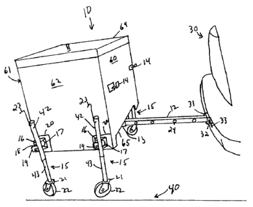
Fig. 1 shows a front view of the portable hitch mounted cargo carrier of the
present invention.
Fig. 2 shows a hitch shaft inserted into a receiver style trailer hitch on a
vehicle.
2


CA 02560578 2006-09-21
Fig. 3 shows the cargo carrier elevated by the j ack mechanisms in the legs so
that
the hitch sleeve will fit over the hitch shaft and the carrier can be pushed
towards the
vehicle.
Fig. 4 shows the cargo carrier pushes towards the vehicle and the legs rotated
upwards so that the cargo carrier can be transported by the vehicle.
Fig. 5 shows a perspective view of the hitch sleeve which is attached on the
bottom of the cargo carrier.
Fig. 6 shows the features of the cargo carrier legs in more detail.
Fig. 7 shows the features ofthe screw type jack inside the cargo carrier legs
in
more detail.
Fig. 8 shows the cargo earner sleeve base and leg clamp frame in more detail.
Detailed Description of the Invention
While the following description details the preferred embodiments of the
present
invention, it is to be understood that invention is not limited in its
application to the
details of construction and arrangement of the parts illustrated in the
accompanying
drawings, since the invention is capable of other embodiments and of being
practiced in
various ways.
The cargo carrier 10 of the present invention is shown in Fig. 1. The cargo
carrier
10 has a front 60, a back 61 (see Fig. 3), a left side 62, a right side 63, a
top 64, and a
bottom 65. Top 64 is constructed as a lid 11. Front 60 has a pair of hitch
shaft holders 14
to hold hitch shaft 12 when cargo carrier 10 is not hitched to a vehicle.
Bottom 65 has a
hitch sleeve 13 centered on bottom 65. Left side 62 and right side 63 each
have a pair of
telescoping legs 15 and sleeves 17. Each leg has a clamp frame 16 which is
fixed
rotatably to sleeve 17. Clamp frame 16 has locking pins 18 (see Fig. 8) which
form
locking pin handle 19. Legs 15 have casters 21 with wheels 22. Legs 15 also
have a jack
handle 23 which operates a screw type jack 44 (see Fig. 7) to raise and lower
legs 15.
Hitch shaft 12 has holes 24 to reversibly attach hitch shaft 12 to hitch
sleeve 13 and to a
trailer hitch 31 on a vehicle 30 (see Fig. 2).
3


CA 02560578 2006-09-21
Fig. 2 shows hitch shaft 12 inserted into vehicle trailer hitch 31 on vehicle
30.
~~ehicle trailer hitch 31 has a hole 32 which can be aligned with a hitch
shaft hole 24. A
locking bolt 33 can be inserted through holes 32 and 24 to hold hitch shaft 12
firmly in
place in vehicle trailer hitch 31.
S Fig. 3 illustrates the telescoping feature of legs 15. Legs 15 have a lower
portion
43 which fits slideably into upper leg portion 42. Jack handle 23 can be
rotated to operate
a screw type jack 44 inside the upper 42 and lower 43 portions of leg 15 (see
Fig. 7).
Screw type jack 44 can extend lower leg portion 43 out of upper leg portion
42, thereby
increasing the length of leg 15. Screw type jack 44 can withdraw lower leg
portion 43
into upper leg portion 42, thereby shortening the length of leg 15. Cargo
Garner 10 can be
raised by increasing the length of legs 15 and lowered by decreasing the
length of legs
15. Fig. 3 shows that legs 15 have been lengthened to raise cargo carrier 10
so that hitch
s;eeve 13 fits over hitch shaft 12. Cargo carrier 10 can be pushed forward on
the ground
40 towards vehicle 30 so that hitch sleeve 13 moves over hitch shaft 12 and
hitch shaft
holes 24 align with holes 41 in hitch sleeve 13 (see Fig. 5). Locking bolts 33
can be
inserted through holes 24 and 41 to hold hitch shaft 12 firmly in place in
hitch sleeve 13.
In this manner cargo carrier 10 can be securely attached to vehicle 30. Fig. 3
also shows a
seeve base 20 attached to cargo earner 10. Sleeve base 20 has a sleeve 17.
Clamp frame
16 fits rotatably on sleeve 17, thereby rotatably fixing legs 15 to cargo
carrier 10.
Fig. 4 shows cargo carrier 10 pushed towards vehicle 30. The lower portions 43
o f legs 15 have been withdrawn into upper portions 42 of legs 15, and legs 15
have been
rotated upward off the ground 40. Cargo carrier 10 can now be safely
transported by
vehicle 30. Cargo carrier 10 can be removed from vehicle 30 by rotating the
legs 15
toward the ground and operating the jack 44 to lower the lower leg portions 43
to the
ground 40 so that wheels 22 touch ground 40. Bolts 33 can be removed from
holes 24,
32, and 41, and cargo carrier 10 can be pulled away from vehicle 30 so that
hitch sleeve
13 comes off of hitch shaft 12. Hitch shaft 12 can be removed from trailer
hitch 31 and
placed into hitch shaft holders 14. Cargo carrier 10 can then be moved on its
wheels 22 to
any desired location.
Fig. 5 illustrates the features of hitch sleeve 13. Hitch sleeve 13 has a top
70, a
right side 71, a left side 72 and holes 41. Hitch sleeve 13 is constructed to
fit over hitch
4


CA 02560578 2006-09-21
shaft 12 so that holes 41 align with holes 24 in hitch shaft 12. Top 70 of
hitch sleeve 13 is
a~tached to bottom 65 of carrier 10, preferably in the center of bottom 65.
Fig. 6 shows the features of leg 15 in more detail. Sleeve base 20 is fixed to
cargo
carrier 10. Sleeve base 20 has a sleeve 17 extending outward from base 20.
Clamp frame
16 fits rotatably over sleeve 17. Clamp frame 16 is fixed to leg 15 so that
leg 15 is
thereby fixed rotatably to sleeve 17. Clamp frame 16 has a locking pin
mechanism
v~hereby locking pins 18 fit into locking pin holes 54 in sleeve base 20,
thereby keeping
legs 15 in a locked position. Pulling outward on locking pinhandle 19
withdraws the
locking pins 18 from locking pin holes 54, and legs 15 can then be rotated to
any desired
position.
Fig. 7 shows the features of screw type jack 44 in more detail. Upper portion
42
of leg 15 has a handle 23 inserted into upper portion 42. The part of handle
23 inside
upper portion 42 has a gear 48 which engages a gear 49, forming a worm gear
45. Gear
49 is attached to one end of a threaded screw shaft 46. The opposite end of
the threaded
screw shaft 46 engages a threaded nut 47 at the top of lower leg portion 43.
As handle 23
is rotated the worm gear 45 causes the screw shaft 46 to rotate, screwing the
screw shaft
46 into or out of threaded nut 47, depending on which direction the handle 23
is rotated.
As screw shaft 46 is screwed into threaded nut 47, lower leg portion 43 is
withdrawn into
upper leg portion 42. As screw shaft 46 is screwed out of threaded nut 47,
lower leg
portion 43 is extended out of upper leg portion 42. This screw type jack 44
allows several
hundred pounds to be easily raised or lowered in cargo carrier 10. These kinds
of screw
type jacks are known and can be purchased from Harbor Freight Tools,
Birmingham,
Alabama.
Fig. 8 shows the features of clamp frame 16 and sleeve base 20 in more detail.
Sleeve base ZO is fixed to cargo carrier 10, preferably on the sides 62 and 63
near bottom
65. Sleeve base 20 has a sleeve 17 which extends outward. Sleeve 17 has a snap
ring
groove 50 to lock clamp frame 16 rotatably onto sleeve 17 by means of a snap
ring (not
mown). Sleeve base 20 has a plurality of locking pin holes 54 for receiving
locking pins
18 to lock clamp frame 16 in position.
Clamp frame 16 has contours 55 constructed to fit around upper leg portion 42
so
that clamp frame 16 can be welded to upper leg portion 42. Clamp frame 16 also
has a
5


CA 02560578 2006-09-21
hole 51 constructed to fit over sleeve 17 so that clamp frame 16 can rotate
around sleeve
17. Clamp frame 16 has holes 53 to accommodate locking pins 18. Locking pins
18 have
first ends 80 which fit into locking pin holes 54. Locking pins 18 have
opposite ends 81
v-hich are continuous to form locking pin handle 19. Locking pins 18 have
springs 52
v~hich bias locking pins 18 into locking pin holes 54 on sleeve base 20.
Locking pins 18
can be removed from locking pin holes 54 by pulling on locking pin handle 19.
Thus, by
pulling on locking pin handle 19, legs 15 can be rotated to any desired
position. When
locking pins 18 are aligned with any given pair of locking pin holes 54, legs
15 can be
locked into a desired position by releasing locking pin handle 19. In this
manner, legs 15
can be rotated upward towards the cargo carrier 10 or downward towards the
ground 40.
The foregoing description has been limited to specific embodiments of this
invention. It will be apparent, however, that variations and modifications may
be made by
those skilled in the art to the disclosed embodiments of the invention, with
the attainment
of some or all of its advantages and without departing from the spirit and
scope of the
IS present invention. For example, legs 15 can be mounted inside cargo carrier
10 so that
lower leg portions 43 are able to extend through holes in the bottom 65 of
carrier 10, and
jack handle 23 extends through the side of cargo carrier 10. Legs 15 can be
mounted on
the front 60 and back 61 of carrier 10. The components of the present
invention can be
made of metal, plastic, or a combination thereof. A single handle can be
constructed to
operate all the jack mechanisms simultaneously by connecting all the gears 48
with
s'lafts. The jacks can be powered with electric motors.
It will be understood that various changes in the details, materials, and
a:-rangements of the parts which have been described and illustrated above in
order to
explain the nature of this invention may be made by those skilled in the art
without
departing from the principle and scope of the invention as recited in the
following claims.
6

Representative Drawing
A single figure which represents the drawing illustrating the invention.
Administrative Status

For a clearer understanding of the status of the application/patent presented on this page, the site Disclaimer , as well as the definitions for Patent , Administrative Status , Maintenance Fee  and Payment History  should be consulted.

Administrative Status

Title Date
Forecasted Issue Date Unavailable
(22) Filed 2006-09-21
(41) Open to Public Inspection 2007-04-14
Dead Application 2010-09-21

Abandonment History

Abandonment Date Reason Reinstatement Date
2009-09-21 FAILURE TO PAY APPLICATION MAINTENANCE FEE

Payment History

Fee Type Anniversary Year Due Date Amount Paid Paid Date
Application Fee $400.00 2006-09-21
Maintenance Fee - Application - New Act 2 2008-09-22 $100.00 2008-08-11
Owners on Record

Note: Records showing the ownership history in alphabetical order.

Current Owners on Record
MYREX, LEE
Past Owners on Record
None
Past Owners that do not appear in the "Owners on Record" listing will appear in other documentation within the application.
Documents

To view selected files, please enter reCAPTCHA code :


To view images, click a link in the Document Description column. To download the documents, select one or more checkboxes in the first column and then click the "Download Selected in PDF format (Zip Archive)" or the "Download Selected as Single PDF" button.

List of published and non-published patent-specific documents on the CPD .

If you have any difficulty accessing content, you can call the Client Service Centre at 1-866-997-1936 or send them an e-mail at CIPO Client Service Centre.


Document
Description 
Date
(yyyy-mm-dd) 
Number of pages   Size of Image (KB) 
Cover Page 2007-04-04 2 54
Abstract 2006-09-21 1 23
Description 2006-09-21 6 283
Claims 2006-09-21 8 259
Drawings 2006-09-21 5 96
Representative Drawing 2007-03-28 1 16
Assignment 2006-09-21 2 70
Fees 2008-08-11 1 34