Note: Descriptions are shown in the official language in which they were submitted.
CA 02560777 2006-09-20
WO 2006/030464 PCT/IT2004/000506
APPARATUS FOR FEEDING POUCHES AND THEIR RESPECTIVE
SPOUTS TO A ROTARY MACHINE FOR THE PROCESSING OF THE
SAME AND RELATIVE METHOD.
s TECHNICAL FIELD AND BACKGROUND ART.
The present invention relates to an apparatus for feeding pouches and their
respective spouts to a rotary machine for the processing of the same and
relative
feeding method.
As is well known, drinks, and in particular fruit juices and sporks drinks,
are
io increasingly more frequently sold and preserved in flexible containers
commonly known as "pouches".
Generally, these flexible containers comprise a pouch, normally made of
polyethylene (PE) and have a spout, to enable the product contained inside the
container to be poured out.
is Pouring of the product is particularly facilitated by the possibility to
exert
pressure on the beverage by squeezing the pouch.
The flexible containers, or pouches, are made from a pair of polyethylene
sheets
the edges of which are welded together leaving an opening.
Into this opening a portion of the spout is inserted and secured by means of
zo welding. In particular, this welding concerns the edges of the opening and
is
performed by applying heat to partially melt said edges so that they adhere to
the portion of the spout inserted in the pouch.
Generally, the spout is inserted inside the opening before the container is
filled.
It is well known that systems already exist for the processing of pouches
zs comprising rotary machines with starwheels for picking up and transfernng
the
i
CA 02560777 2006-09-20
WO 2006/030464 PCT/IT2004/000506
pouches, that work together with one or more starwheels for filling and
sealing
the pouches.
An important feature of systems with rotary machines is that they can operate
in
continuous mode and thus guarantee high productivity.
s To take full advantage of this feature, it is essential that a continuous
flow of
pouches be fed to the processing starwheel.
In particular, since the pouches are assembled directly on the welding
starwheels
by opening the said pouches, inserting the spout inside the opening and then
welding the edges of the pouch, both the pouches and the spouts must be fed to
io the processing starwheel.
The problem of ensuring continuous feed of both pouches and spouts to the
rotary machine has yet to be resolved.
DISCLOSURE OF THE INVENTION.
It is an object of the present invention to resolve the above-mentioned
problem
is by providing an apparatus that can feed the pouches and their respective
spouts
to a rotary machine for the processing of the same, having the capacity to
ensure
continuous feeding of both spouts and pouches.
Further, it is an object of the present invention to create an apparatus to
simultaneously feed both pouches and spouts to a rotary machine for .the
zo processing of the same.
Further still, it is an object of the present invention to present an
apparatus for
feeding pouches and their respective spouts which is able to guarantee high
productivity.
Further still, it is an object of the present invention to present an
apparatus for
zs feeding pouches and their respective spouts which is easy to construct and
2
CA 02560777 2006-09-20
WO 2006/030464 PCT/IT2004/000506
reliable.
Further still, it is an object of the present invention to present a method
for
feeding pouches and spouts to a rotary machine for the processing of the same
that is easy to implement.
s The above objects are fully attained through the apparatus for feeding
pouches
and their respective spouts to a rotary machine for the processing of the same
and by the relative method, object of the present invention, characterized by
the
contents of the claims reported below.
BEST MODE FOR CARRYING OIIT THE INVENTION.
io This and other objects shall become more readily apparent in the following
description of a preferred embodiment illustrated, purely by way of non
limiting
example, in the accompanying drawing tables in which:
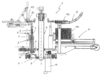
- figure 1 is a partially sectioned front view of an apparatus for feeding
pouches
and their respective spouts to a rotary machine for the processing of the
same;
is - figure 2 is a diagram, viewed from above, showing the principle of
operation
of the apparatus shown in figure 1.
With reference to the f gores, an apparatus for feeding pouches and their
respective spouts to a rotary machine for the processing of the same is
globally
indicated by the number 1. In particular, the rotary machine can be, for
example,
2o a pouch-forming starwheel equipped with welding grippers to weld the spouts
to
the pouches.
The apparatus 1 comprises a first magazine 2 designed to contain a stock of
pouches 102 and a second magazine 3 designed to hold a set number of spouts
103.
2s In a totally new and original manner, the apparatus 1 comprises a handling
unit
3
CA 02560777 2006-09-20
WO 2006/030464 PCT/IT2004/000506
4 designed so as to be able to pick up a pouch 102 and a spout 103 from their
respective magazines and feed them simultaneously, and in continuous mode, to
a rotary machine.
In the example illustrated, the handling unit 4 is secured to a rotating
platform 6
s keyed to a first support shaft 5.
In particular, the handling unit 4 also comprises a second support shaft 7
which
is mobile so as to be able to rotate around the first vertical axis A, between
an
operating position of picking up of a pouch 102 and of a spout 103 and an
operating position for transferring the same to the rotary machine. The means
io for picking up a pouch and the means for picking up a spout are installed
on the
said second support shaft 7.
In the example illustrated, said means for picking up a pouch consist of a
pair of
suction cups 8, 9 vertically aligned and arranged on the same vertical plane P
(in
figure 1, said vertical plane P is viewed from the side).
is In the embodiment illustrated, the means for picking up a spout is
preferably a
gripper 10.
With particular reference to figure 1, the second support shaft 7 is secured
perimetrically to the rotating platform 6, which rotates around a second axis
B
which is substantially vertical and which passes through the said first
support
ao shaft 5. More precisely, the second support shaft 7 revolves around the
first
vertical axis A at the same time as the rotating platform 6 rotates around the
second vertical axis B, so that the suction cups 8, 9 and the gripper 10 are
activated by hypocycloid movement as they travel from magazines 2 and 3 to
the rotary machine for the processing of pouches and spouts.
as With particular reference to the embodiment shown in figure 1, the rotating
4
CA 02560777 2006-09-20
WO 2006/030464 PCT/IT2004/000506
platform 6 is moved directly by the rotary machine for the processing of
pouches and spouts, for example through a mechanical coupling of toothed
gears 30 integral to the rotary machine and corresponding toothed gears 31,
integral to the rotating platform 6.
s In the example illustrated, the second rotating shaft 7 is preferably moved
by an
electric motor 11 secured to the rotating platform 6 and therefore integral to
said
platform.
In the embodiment shown, the apparatus 1 for feeding pouches and their
respective spouts is preferably built of a singler rotating platform and
several
io second rotating shafts 7, each of which equipped with at least a pair of
suction
cups for picking up and holding a pouch and at least one gripper for picking
up a
spout.
The method for feeding the pouches and spouts to the rotary machine for the
processing of the same comprises the following phases:
is arranging a magazine of pouches;
arranging a magazine of spouts;
picking up of a pouch (102) from the corresponding magazine (2); and
picking up of a spout (103) from the corresponding.magazine (3).
In a new and original manner, the method of the present invention comprises a
zo step of simultaneous, continuous feeding of the pouches and spouts to the
rotary
machine for the processing of the same.
Preferably, the step of feeding pouches and spouts to the rotary machine for
the
processing of the same takes place through hypocycloid movement of the
pouches and spouts from the magazines to a discharge point on said rotary
zs machine.
s
CA 02560777 2006-09-20
WO 2006/030464 PCT/IT2004/000506
The principle of operation of the invention is as follows.
The rotating platform 6 is powered directly by the rotary machine for the
processing of pouches and spouts through the coupling of toothed gears 30
integral to the rotary machine and toothed gears 31 integral to the rotating
s platform 6.
At the same time, the support shaft 7 which is part of the handling unit 4 is
made
to rotate around the first axis A by the electric motor 11, integrally secured
to
rotating platform 6.
In this way, the suction cups ~, 9 and the gripper 10 are moved by hypocycloid
io movement, travelling from the area where the pouches 102 and spouts 103 are
picked up from their magazines 2, 3 to the area where the pouches and spouts
are transferred to the rotary machine for the processing of the same
(indicated
with the letter R in figure 2).
In particular, as shown in figure 2, the trajectory followed by the suction
cups 8,
is 9 and the gripper 10 is indicated by point Q. Specifically, this point
describes a
cusp at magazines 2, 3 containing the pouches and spouts (only the magazine
containing the pouches 102 is shown in figure 2), so that the absolute speed
of
movement of the suction cups and of the gripper is cancelled out. In this way,
the suction cups and the gripper can pick up the pouches 102 and the spouts
103
Zo (which are not moving) without "wrenching" them from their respective
magazines.
Subsequently, point Q shown in figure 2, follows a trajectory which
substantially describes a circumferential arch so that the relative speed of
the
suction cups 8, 9, and of the gripper 10 vs. the rotary machine R is cancelled
out.
zs In this way, the suction cups and the gripper are able to transfer the
pouches 102
6
CA 02560777 2006-09-20
WO 2006/030464 PCT/IT2004/000506
and spouts 103 to the rotary machine R in a precise manner.
The principle of operation described above refers to an apparatus equipped
with
a single handling unit 4, but it is identical for apparatuses equipped with
several
of these handling units.
s This invention offers some important advantages.
First of aII, an apparatus in accordance with the present invention is able to
feed
both spouts and pouches in continuous mode, thus guaranteeing high
~.
productivity.
Another important advantage of the present invention is that it can feed both
io spouts and pouches simultaneously.
Advantageously, an apparatus in accordance with the present invention is
compact and extremely reliable.
A further advantage of the present invention is that it can handle pouches and
spouts safely and without damaging them while till ensuring high productivity.