Note: Descriptions are shown in the official language in which they were submitted.
CA 02561105 2006-09-26
MULTIFUNCTIONAL SPRINKLER STRUCTURE
BACKGROUND OF THE INVENTION
The present invention relates to a multifunctional sprinkler structure,
comprising a water motor having an outlet seat and a top cover mounted to a
top-end
side, and two adjusting seats and a water supply seat assembled onto a bottom-
end
side wherein barriers of the outlet seat and water-guiding ribs of the spray
nozzle are
utilized to correspond to the direction of the water flow so that the water
discharge
can be easily switched to eject either in more direct and forceful column-like
spray or
in more expanding spray.
Conventional sprinklers (referring to US Patent No. 5611488 and German
Patent No. DE4329616A1) include some disadvantages. For example, when the
sprinkling control unit is adjusted to swing to the maximum angle, a switch
shaft can
hinder the smooth rotation of the sprinkler, which tends to make the sprinkler
fail to
swing a full 360 degrees and cause uneven distribution of the water discharge
sprinkled onto the lawn thereon. Thus, the conventional sprinklers are reduced
in
function.
SUMMARY OF THE PRESENT INVENTION
It is, therefore, the primary purpose of the present invention to provide a
multifunctional sprinkler structure, comprising a water motor having an outlet
seat
and a top cover mounted to a top-end side, and two adjusting seats and a water
supply
seat assembled onto a bottom-end side wherein barriers of the outlet seat and
water-guiding ribs of a spray nozzle are utilized to correspond to the
direction of
1
CA 02561105 2006-09-26
water flow. When the water flow propels an impeller to rotate towards the
direction
of the barriers, the impetus of the water flow hindered by the barriers will
become
weakened. And when the water flow enters the spray nozzle, the water flow will
run
in a direction counter to that of the water-guiding ribs and further hindered
thereby.
Thus, the water flow will concentrate in the center of the spray nozzle to
emit
outwards in more direct and forceful column-like spray. However, when the
water
flow propels the impeller to spin towards the other side thereof, the water
flow
released from the hindrance of the barriers will flush directly towards the
spray nozzle.
Then, the water flow will run in a direction identical to that of the water-
guiding ribs,
and the water flow guided by the ribs will keep augmenting its impetus to
eject in a
radial direction outwards in more expanding spray thereby.
It is, therefore, the second purpose of the present invention to provide a
multifunctional sprinkler structure wherein a switch shaft is applied to
locate at one
side of a sliding groove of a linking piece therein, which presets an
appropriate space
and allows the water motor to keep rotating till the switch shaft swinging
from one
side of the sliding groove to the other side thereof and pressed thereby so as
to switch
the direction of the water flow. Therefore, the sprinkler can operate
accurately to
achieve precise back-and-forth swing in 360 degrees so that the water
discharge can
be evenly distributed to sprinkle onto the lawn.
It is, therefore, the third purpose of the present invention to provide a
multifunctional sprinkler structure wherein the top cover has an assembling
groove
for the engagement of a control piece therewith, and the control piece can be
movable
slid outwards to extend above the spray nozzle and hinder the water flow
ejecting
outwards in low parabola spray. Otherwise, the control piece is retrieved to
locate at
the assembling groove therein, permitting the water flow released from the
hindrance
thereof to emit outwards in high parabola spray. Thus, the sprinkler can be
easily
2
CA 02561105 2006-09-26
adjusted to switch the height of the water discharge sprinkling onto the lawn
in either
farther or nearer range, achieving more flexible application of the sprinkler
and
boosting its functions thereof.
BRIEF DESCRIPTION OF THE DRAWINGS
Fig. 1 is an exploded perspective view of the present invention.
Fig. 2 is a flat view of a linking piece and adjusting seats of the present
invention
assembled onto a water motor.
Fig. 3 is a diagram showing the operation of the linking piece synchronically
moved
with the water motor of the present invention.
Fig. 4 is a diagram showing the water motor of the present invention rotated
to 360
degrees in operation.
Fig. 5 is another exploded perspective view of the present invention.
Fig. 6 is a diagram showing the interior of an outlet seat of the present
invention.
Fig. 7 is an assembled and partially cross sectional view of the present
invention.
Fig. 8 is a diagram showing the direction of the water flow hindered by
barriers
disposed at the interior of the outlet seat thereof.
Fig. 9 is a diagram showing the water flow of Fig. 8 running counter to and
hindered
by water-guiding ribs disposed at the interior of a spray nozzle thereof.
Fig. 10 is a diagram showing the water flow of Fig. 9 ejecting outwards in
straight
spray.
Fig. 11 is a diagram showing the water flow unhindered by the barriers of the
outlet
seat and directly guided into the spray nozzle thereof.
Fig. 12 is a diagram showing the water flow of Fig.l 1 running identically to
the
direction of the water-guiding ribs of the spray nozzle and augmenting its
3
CA 02561105 2006-09-26
impetus thereby.
Fig. 13 is a diagram showing the water flow of Fig. 12 ejecting outwards in
expanding spray.
Fig. 14 is a third exploded perspective view of the present invention.
Fig. 15 is a perspective view taken from a bottom side of a control piece of
the present
invention.
Fig. 16 is a perspective view showing the interior of a top cover of the
present
invention.
Fig. 17 is a diagram showing the water flow of the present invention
unhindered by
the control piece and ejecting outwards in high parabola spray.
Fig. 18 is a diagram showing the control piece moved to the front end of the
top cover
with the water flow hindered by a stop plate and ejecting in low parabola
spray.
DETAILED DESCRIPTION OF THE PREFERRED EMBODIMENTS
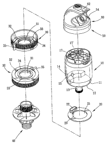
Please refer to Figs. 1, 2. The present invention relates to a multifunctional
sprinkler structure, comprising a water motor 10, a linking piece 20, two
adjusting
seats 30, a water supply seat 40, an outlet seat 50, and a top cover 60. The
water
motor 10 has a bottom-end side 11 with a guide edge 12 extending downwards
from
the external periphery, and a connector protruding in the middle for the
extension of
an inlet tube 13 there-through. The bottom-end side 11 has an arcuate guide
groove 14 with a restrictive hole indented at one side thereon for the
extension of a
switch shaft 15 there-through. The linking piece 20 and the two adjusting
seats 30
are respectively equipped with a bore 21, 31 extending through the center
thereon to
be sequentially guided through the inlet tube 13 and mounted to the water
motor 10
thereby. The linking piece 20, abutting against the bottom-end side 11, is
restricted
4
CA 02561105 2006-09-26
by the guide edge 12 to keep an even surface therewith. The linking piece 20
has
one side equipped with an arcuate sliding groove 22 and a push shaft 23
respectively
situated at the corresponding top and bottom surfaces thereon, permitting the
switch
shaft 15 to precisely accommodate into the sliding groove 22 thereby. The two
adjusting seats 30 are correspondingly joined to the bottom-end side 11 of the
water
motor 10. And the inner surface of the adjusting seat 30 is equipped with
multiple
guide blocks 32 to precisely abut against the guide edge 12 thereon,
permitting the
linking piece 20 to keep an appropriate distance from the inner surface of one
adjusting seat 30 thereby. Each adjusting seat 30 also includes a positioning
passage
34 annularly defining thereon and a stop rib 33 extending at the positioning
passage
34 thereon. Thus, the push shaft 23 is allowed to precisely accommodate into
the
positioning passage 34 and limited in position by the stop rib 33 thereof.
Besides, an
angle-adjusting plate 35 is provided protruding at the outer periphery of the
adjusting
seat 30 in opposite to the stop rib 33 thereof. The angle-adjusting plate 35
has a
height identical to that of the adjusting seat 30. The water supply seat 40 is
coupled
with one of the two adjusting seats 30 and securely joined to the inlet tube
13 so that
water flow is allowed to run through the water supply seat 40 and the inlet
tube 13 to
enter the water motor 10 thereby.
Please refer to Figs. 3, 4. When the two angle-adjusting plates 35 of the two
adjusting seats 30 are regulated into the same position, the switch shaft 15
accommodated into the sliding groove 22 of the linking piece 20
correspondingly
works with the push shaft 23 received into the positioning passages 34 and
restricted
in position by the stop ribs 33 of the adjusting seats 30 thereof. The switch
shaft 15
will slide along with the rotation of the water motor 10 to contact one side
of the
sliding groove 22 and actuate the linking piece 20 to slide along the guide
edge 12 and
synchronically move with the water motor 10 till the push shaft 23 sliding
along the
CA 02561105 2006-09-26
positioning passages 34 of the adjusting seats 30 is hindered by the stop ribs
33
thereof. Then, the linking piece 20 will stop revolving, and the switch shaft
15
positioned at one side of the sliding groove 22 presets an appropriate space,
permitting the water motor 10 to keep rotating till the switch shaft 15
swinging from
one side of the sliding groove 22 to the other side and pressed thereby so as
to switch
the direction of the water flow thereby. Therefore, the sprinkler can operate
accurately to swing back and forth in 360 degrees so that the water discharge
can be
evenly distributed to sprinkle onto the lawn.
Please refer to Fig. 5 showing a second exploded perspective view of the
present invention. The water motor 10 has a top-end side 16 with two outlet
orifices
17, 17' extending there-through to correspond to an impeller 18 accommodated
to a
water-intake chamber 181 therein. The outlet seat 50 (referring to Fig. 6),
mounted
to the top-end side 16 of the water motor 10, is provided with a water-
discharge
chamber 51 indented at the interior therein to correspond to the impeller 18
thereof.
The water-discharge chamber 51 has multiple barriers 52 extending at one
sidewall,
and a guide port 53 obliquely extending through the center thereon to match to
a spray
nozzle 54 thereby. The spray nozzle 54 has an internal wall equipped with
multiple
oblique-extension water-guiding ribs 541 identically slanting towards the same
direction thereof. The top cover 60 (referring to Fig. 7) is mounted on top of
the
outlet seat 50 thereon.
Please refer to Fig. 8. When the water flow collectively goes through one
outlet orifice 17 of the water motor 10, the water flow gathered in the water-
intake
chamber 181 will propel the impeller 18 to rotate towards the direction of the
barriers
52. The impetus of the water flow hindered by the barriers 52 will become
weakened thereby. Then, when the water flow enters the spray nozzle 54, the
water
flow will run in a direction counter to that of the water-guiding ribs 541 as
shown in
6
CA 02561105 2006-09-26
Fig. 9, which will further decrease the impetus of the water flow thereby.
Thus, the
water flow will concentrate in the center of the spray nozzle 54 to eject
outwards in
more direct and forceful column-like spray as shown in Fig. 10. However, when
the
water flow comes out through the other outlet orifice 17', the impeller 18
will be
propelled to spin towards the other side as shown in Fig. 11 so that the water
flow
released from the hindrance of the barriers 52 will flush directly towards the
spray
nozzle 54. Then, the water flow will run in a direction identical to that of
the
water-guiding ribs 541 as shown in Fig. 12, and the water flow guided by the
ribs 541
will keep augmenting its impetus to eject in a radial direction outwards in
more
expanding spray as shown in Fig. 13.
Referring to Figs. 14 to 16 inclusively. The top cover 60 has an assembling
groove 61 indented at the top surface thereon to which a control piece 62 with
a stop
plate 621 extending thereon is reciprocally joined. The assembling groove 61
has a
bottom defined by a limiting slot 612 with multiple adjusting toothed recesses
611
disposed at both lateral sidewalls thereon. Besides, an opening 613 is
disposed at the
front side of the assembling groove 61 to correspond to the stop plate 621
thereby.
The control piece 62 has a pair of flexible hooked legs 622 protruding at the
bottom
thereon to precisely hook to both bottom lateral sides of the limiting slot
612 thereby.
Each flexible hooked leg 622 has a toothed rib 623 protruding at the external
side to
mesh with the adjusting toothed recesses 611 thereby. When the control piece
62 is
inserted into the assembling groove 61, the water flow ejecting outwards from
the
spray nozzle 54 without any hindrance will sprinkle outwards in high parabola
spray
as shown in Fig. 17 so as to distribute the water discharge onto the lawn in
farther
range. However, when the flexible hooked legs 622 of the control piece 62 are
guided along the limiting slot 612 of the assembling groove 61 to push the
stop plate
621 extending outwards through the opening 213, the water flow ejecting
outwards
7
CA 02561105 2006-09-26
from the spray nozzle 54 will be hindered by the stop plate 621 to emit
outwards in
low parabola spray as shown in Fig. 18 so as to sprinkle the lawn in nearer
range.
Therefore, the sprinkler of the present invention can provide more flexible
operation
and is highly boosted in functions.
8